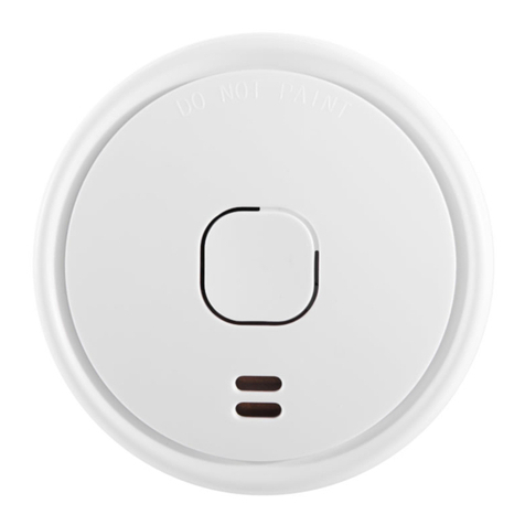
1. ULLS10RF PRODUCT OVERVIEW
All UltraFire Photoelectric type smoke alarms are approved to the most
recent and rigorous European Smoke Alarm Standard. The unique X-Prole
Photoelectric sensing chamber is particularly sensitive to slow smouldering res
typically originating in living rooms, bedrooms and hallways whilst being highly
resistant to nuisance alarms.
Product Features
• Radio interlinkable to other UltraFire 10 year smoke and heat alarms. By
connecting up to 15 alarms, they will be connected by radio link so that
when one alarm sounds all connected alarms will sound.
• Two sealed in long life batteries.
• Approved to EN14604:2005, Smoke alarm devices.
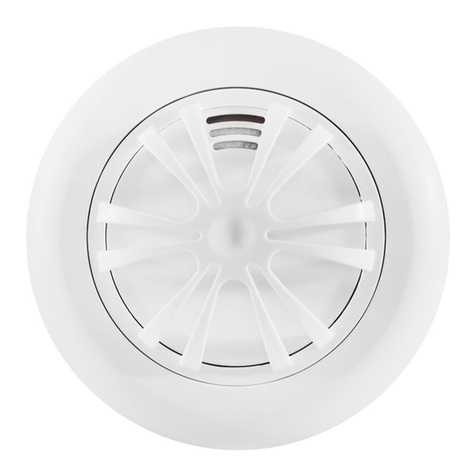
• Unique X-Prole detection chamber with insect screen.
• Bespoke software maximizes detection ability, false alarm rejection and
Alarm Silence operation.
• Power automatically switched on as a alarm is installed onto its mounting
plate and automatically switched o when alarm is removed.
• Red LED on the alarm and the green one on the side of the mounting
pattress will ash approximately every minute conrming unit is receiving
power and ready to detect and transmit re conditions. (Quiescent Mode)
• Low Battery Warning - End of alarm life, alarm gives one beep every
minute.
• Low Battery Warning Silence - Low battery warnings often start at night.
Silence the audible warning for ten hours by pressing the test button, thus
avoiding removing the alarm from its mounting plate. The alarm can then
be replaced when convenient the following day.
• Extra Large Test Button for ease of use, tests sensitivity, circuitry, battery
and alarm sounder.
• Loud 85 Decibel Piezo Electric Alarm - Automatically resets when
hazardous condition has passed and chamber is clear.
• Alarm Silence - Silence your smoke alarm by momentarily pressing the
test button. Ideal in non-emergency situations where nuisance alarms
may have been created, for example, by steam. The red light ashes
every 12 seconds to remind you that the smoke alarm has been silenced
and will automatically reset to quiescent mode in 10 minutes.
• Approved for use in Leisure Accommodation Vehicles.
2. CHOICE AND LOCATION OF ALARMS
Photoelectric Smoke Alarms are best for sensing smouldering res and
therefore best suited for rooms containing furniture, bedding and clothes
such as escape routes, lounges, bedrooms and other living rooms. They are
recommended by BS 5839 pt6 for living accommodation where most res
originate in electrical equipment and smouldering material such as furniture,
clothing, curtains and carpets.
NOTE: Heat Alarms are most suitable for kitchens, boiler rooms, workshops
and garages where dust, dirt and moisture would contribute to nuisance alarms.
Heat alarms should not be used on walls or in escape routes and should
always be interlinked to smoke alarms. Do not install heat alarms in sleeping
areas; for example, bedrooms, nurseries, playrooms or areas where the elderly
and disabled may spend long periods of time.
For minimum protection, install at least one smoke alarm on each level of your
home. They should be installed in hallways, corridors and all escape routes
from the building and within 3 meters of all bedroom doors. All alarms should
be interconnected.
Recommended siting of smoke and heat alarms in:
SINGLE STOREY HOME WITH ONE
SLEEPING AREA
SINGLE STOREY HOME WITH TWO
SLEEPING AREAS
MULTIPLE STOREY HOME WITH
MULTIPLE SLEEPING AREAS
6. Do not install less than 300mm from walls and light ttings when mounted
on the ceiling where heat and dead air may delay smoke reaching the alarm.
7. Do not install in insect infested areas.
8. Do not install in areas subjected to heavy concentrations of cigarette smoke
that will cause nuisance alarms and the alarm to become contaminated.
9. Do not install smoke alarms in kitchens, boiler rooms and garages where
fumes and dust may cause nuisance alarms.
10. Do not install on poorly insulated walls and ceilings where cold air boundary
layers could prevent smoke reaching the alarm.
11. Do not install near objects that could prevent smoke and heat reaching the
alarm.
12. Do not install within 1500mm of uorescent light tting that could trigger
nuisance alarms.
13. Do not paint the alarm.
The location of the alarms must be in accordance with applicable building
regulations, in particular Part B. Further help and guidance can also be found in
BS5839 part 6.
4. FURTHER DETAIL ON ALARM LOCATION
1. At least one smoke alarm should be installed in the escape route on all
oors of the building.
2. The detection element of smoke alarms should be between 25mm and
600mm below the ceiling, or in the case of heat alarms between 25mm and
150mm
3. Smoke alarms should be at least 300mm from any wall or light tting.
4. If ceiling mounting is impractical smoke alarms may be installed on walls
provided that the area is no longer or wider than 10 metres and the total
area does not exceed 50m2 and that:
a. The detection element is between 150mm and 300mm below the
ceiling.
b. The bottom of the detection element is above openings such as vents,
doors and opening windows
c. Ensure they are not mounted close to or above heaters or air-
conditioning vents.
5. Where smoke alarms are located in a hallway, corridor or landing, the alarm
should be no further than three metres from any bedroom door to assist
audibility behind closed doors.
6. No point on the ceiling in any room, hallway or corridor should be further
than 7.5 metres from any smoke alarm.
7. To give the earliest warning of a developing re, smoke alarms should be
installed in all the rooms of your home and interlinked. (other than those in
point 2 of Choice and Location of Alarms above).
6. INSTALLATION PROCEDURE
Pairing the Radio System
Refer to the separate “Instructions for Pairing Radio Linked Alarms” in the
previous section.
1. When the pairing of the complete system has been completed, test all alarms
to make sure they all link to one another. If they do not, re-pair the alarms
according to the instruction sheet packed with the alarms.
2. Now take the complete alarm to the rooms of their location and test the system
again to make sure that they still operate correctly in their new location
3. Now separate the alarms from their radio pattresses by depressing the
security tag shown below and twisting the alarm anticlockwise
4. Fix them to your nal chosen location by referring to sections 2, 3, and 4
above and re-assemble the alarm to the pattress as shown below
5. You need to ensure surfaces do not contain hazardous materials eg asbestos.
The screw ttings supplied are suitable for use on wood, plaster and
plasterboard but on other surfaces such as concrete where adhesive material
or adhesive pads may be better. For certain applications, the installer may
need to source their own xings.
5. INTERLINK INSTRUCTIONS
1. Preparing the alarms:
a. Plug the alarm into the RF base and switch the RF base on.
b. Fit the alarm onto the RF base and twist to lock them; the alarm will
beep twice to indicate it is powered on.
c. Repeat these steps for all alarms you wish to interlink.
2. Interlinking the alarms:
a. Press the test button on one alarm, wait 3 seconds, and then press
the test button on a second alarm; the alarms will sound a test
sequence.
b. The LED indicators on both RF bases will ash green and red for a
while before one will ash only green, the other will continue with red
and green until it beeps and then will also ash only green.
c. If adding further alarms to the system keep the alarm that beeped in
the last step, move the other to the side, take a new unlinked alarm,
then repeat steps a. and b. until all alarms have been connected.
3. If any RF base ashes red only during the interlinking steps or if you need to
remove an alarm from your system for any reason:
a. Push the security tag in the side of the alarm, then twist to separate
the alarm and the RF base.
b. Press the black button inside the RF base, next to the on/o switch;
the LED on the RF base should ash red four times.
c. You can now attempt to interlink the alarm again, or turn the RF base
o and unplug the alarm to remove it from the system.
RECOMMENDED POSITION OF
ALARMS IN A ROOM, CORRIDOR OR
ESCAPE ROUTE:
3. AVOID THE FOLLOWING LOCATIONS
The life of this alarm can be signicantly reduced by adverse environments,
incorrect location and a failure to regularly clean and maintain it according to the
following instructions. Incorrect location and a lack of reasonable care may also
cause it to malfunction and will invalidate the warranty.
NOTE: Do not store alarms in temperatures below 5°C and above 30°C; this
may cause beeping and nuisance alarms when rst installed. These will clear
after a short time when the alarm has become acclimatised. Extended periods
under these conditions will reduce the life of the alarms and invalidate the
warranty.
1. Do not locate near fans or extractors. These can pull smoke and heat away
from the alarms.
2. Do not install in or near high humidity areas such as showers, bathrooms
or kitchens where humidity levels exceed 85% or the room temperature
exceeds 40° or falls below 0°C. These may cause nuisance alarms and
damage the alarm.
3. Do not install alarms in the peak of an “A’ frame. This may delay smoke and
heat reaching them due to the presence of dead air.
4. Do not install less than 300mm from walls and light ttings when mounted
on the ceiling where heat and dead air may delay smoke reaching the alarm.
5. Do not install in insect infested areas.


