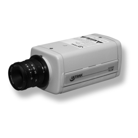
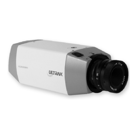
Ultrak KC440xMP User manual

INSTRUCTIONMANUAL
Pleasereadthismanualthoroughlybeforeuse,andkeepithandyforfuturereference.
WorldwideSupportCenter
1301WatersRidgeDrive•Lewisville,TX75057
(800)796-2288(972)353-6400FAX(972)353-6670••
1/3"CCDBLACK&WHITE
CAMERA

Theinformationcontainedhereinissubjecttochangewithoutnotice.Revisionsorneweditionsto
thepublicationmaybeissuedtoincorporatesuchchanges.Usersoftheproductareresponsiblefor
checkingandcomplyingwithallfederal,stateandlocallawsandstatutesconcerningthemonitoring
andrecordingofvideoandaudiosignals.
ULTRAKMAKESNOEXPRESSORIMPLIEDWARRANTIESOFANYNATUREASTOTHE
PRODUCTSINCLUDEDHEREINANDSPECIFICALLYDISCLAIMSALLWARRANTIESOF
MERCHANTABLILTYANDFITNESSFORAPARTICULARPURPOSE.
Allrightsreserved.Nopartofthispublicationmaybereproducedbyanymeanswithoutwritten
permissionfromUltrak.
1998BYULTRAK1998BYULTRAK
ALLRIGHTSRESERVEDALLRIGHTSRESERVED
PRINTEDINKOREAPRINTEDINKOREA
ULTRAKULTRAK
1301WATERSRIDGEDRIVE1301WATERSRIDGEDRIVE
LEWISVILLE,TEXAS75057LEWISVILLE,TEXAS75057
(972)353-6400(972)353-6400
-2-

WARNING:
CAUTION:
ExplanationofGraphicalSymbols
TOREDUCETHERISKOFFIREORELECTRICSHOCK,DONOTEXPOSETHISPRODUCT
TORAINORMOISTURE.DONOTINSERTANYMETALLICOBJECTTHROUGHVENTILATION
GRILLS.
Thelightningflashwitharrowheadsymbol,withinanequilateraltriangle,isintendedto
alerttheusertothepresenceofuninsulated"dangerousvoltage"withinthe
product'senclosurethatmaybeofsufficientmagnitudetoconstituteariskofelectric
shocktopersons.
Theexclamationpointwithinanequilateraltriangleisintendedtoalerttheusertothe
presenceofimportantoperatingandmaintenance(servicing)instructionsintheliterature
accompanyingtheproduct.
-3-
WARNING
ThisisaClassAproduct.Inadomesticenvironmentthisproductmaycause
radiointerferenceinwhichcasetheusermayberequiredtotakeadequate
measures.
CECOMPLIANCESTATEMENT

IMPORTANTSAFEGUARDS
-4-
READINSTRUCTIONS--Allthesafetyandoperating
instructionsshouldbereadbeforetheapplianceisoperated.
RETAININSTRUCTIONS--Thesafetyandoperating
instructionsshouldberetainedforfuturereference.
CLEANING--Unplugvideoequipmentfromthepower
sourcebeforecleaning.Donotuseliquidcleanersoraerosol
cleaners.Useadampclothforcleaning.
ATTACHMENTS--Donotuseattachmentsnot
recommendedbythevideoequipmentmanufacturerasthey
mayresultintheriskoffire,electricshockorinjuryto
persons.
WATERANDMOISTURE--Donotusevideoequipment
nearwater--forexample,nearabathtub,washbowl,kitchen
sink,laundrytub,inawetbasement,ornearaswimming
pool,orthelike.
ACCESSORIES--Donotplacevideoequipmentonan
unstablecart,standortable.Thevideoequipmentmayfall,
causingseriousinjurytoachildoradult,andseriousdamage
totheequipment.Wallorshelfmountingshouldfollowthe
manufacturer'sinstructions,andshoulduseamountingkit
approvedbythemanufacturer.
Videoequipmentandcart
combinationsshouldbemovedwith
care.Quickstops,excessiveforce,
andunevensurfacesmaycausethe
equipmentandcartcombinationtooverturn.
VENTILATION--Slotsandopeningsinthecabinetandthe
backorbottomareprovidedforventilation,andtoensure
reliableoperationofthevideoequipmentandtoprotectit
fromoverheating.Theseopeningsmustnotbeblockedor
covered.Theopeningsshouldneverbeblockedbyplacing
thevideoequipmentonabed,sofa,rug,orothersimilar
surface.Videoequipmentshouldneverbeplacednearor
overaradiatororheatregister.Videoequipmentshouldnot
beplacedinabuilt-ininstallationsuchasabookcaseunless
properventilationisprovided.
POWERSOURCES--V ideoequipmentshouldbeoperated
onlyfromthetypeofpowersourceindicatedonthemarking
label.Ifyouarenotsureofthetypeofpowersuppliedtoyour
home,consultyourvideoequipmentdealerorlocalpower
company.Forvideoequipmentdesignedtooperatefrom
batterypowerrefertotheoperatinginstructions.
1.
2.
3.
4.
5.
6.
6A.
7.
8.
9.
10.
11.
12.
13.
14.
15.
16.
17.
18.
IMPORTANTSAFEGUARDS
LIGHTNING--Foraddedprotectionforvideoequipment
duringalightningstorm,orwhenitisleftunattendedand
unusedforlongperiodsoftime,unplugitfromthewalloutlet
anddisconnecttheantennaorcablesystem.Thiswill
preventdamagetothevideoproductduetolightningand
power-linesurges.
OVERLOADING--Donotoverloadwalloutletsand
extensioncordsasthiscanresultinariskoffireorelectric
shock.
OBJECTANDLIQUIDENTRY--Neverpushobjectsofany
kindintovideoequipmentthroughopeningsastheymay
touchdangerousvoltagepointsorshort-outpartsthatcould
resultinafireorelectricshock.Neverspillliquidofanykind
ontheproduct.
SERVICING--Donotattempttoservicevideoequipment
yourselfasopeningorremovingcoversmayexposeyouto
dangerousvoltageorotherhazards.Referallservicingto
qualifiedservicepersonnel.
DAMAGEREQUIRINGSERVICE--Unplugvideo
equipmentfromthewalloutletandreferservicingtoqualified
servicepersonnelunderthefollowingconditions:
A.Whenthepower-supplycordortheplughasbeen
damaged.
B.Ifliquidhasspilled,orobjectshavefallenintothevideo
product.
C.Ifthevideoproducthasbeene xposedtorainorwater.
D.Ifthevideoproductdoesnotoperatenormallyby
followingtheoperatinginstructions,adjustonlythose
controlsthatarecoveredbytheoperatinginstructionsasan
improperadjustmentofothercontrolsmayresultindamage
andwilloftenrequireextensiveworkbyaqualifiedtechnician
torestorethevideoproducttoitsnormaloperation.
E.Ifthevideoproducthasbeendropped,orthecabinet
damaged.
F.Whenthevideoproductexhibitsadistinctchangein
performance--thisindicatesaneedforservice.
REPLACEMENTPARTS--Whenreplacementpartsare
required,besuretheservicetechnicianhasused
replacementpartsspecifiedbythemanufacturerorthathave
thesamecharacteristicsastheoriginalpart.Unauthorized
substitutionsmayresultinfire,electricshockorother
hazards.
SAFETYCHECK--Uponcompletionofanyserviceor
repairstothisvideoproduct,asktheservicetechnicianto
performsafetycheckstodeterminethatthevideoproductis
inproperoperatingcondition.
FIELDINSTALLATION--Thisinstallationshouldbemadeby
aqualifiedservicepersonandshouldconformtoalllocal
codes.
POWERCORDS--Donotallowanythingtorestonthe
powercord.Donotlocatevideoequipmentwherethecord
willbeabusedbypersonswalkingonit.
HEEDWARNINGS--Followallinstructionsmarkedonthe
videoequipment.


-5-
PURPOSE
INSTALLATIONPRECAUTIONS
SYSTEMINSTALLATION
MAJOROPERATINGCONTROLSANDTHEIRFUNCTION
LENSADJUSTMENT
TROUBLESHOOTING
MAINTENANCE
SPECIFICATION
MAJOROPERATINGCONTROLSANDTHEIRFUNCTION
7
7
8
13
10
11
18
18
19
TABLEOFCONTENTS

-6-
THISPAGEINTENTIONALLYLEFTBLANK

INSTALLATIONPRECAUTIONS
A.
B.
C.
Themountingbracketmustbemountedtoastructuredmembersuchasawall
orceilingrafterusingsuitablefastenerbyinstallguide.
Selectasuitablelocationforthecamera.Installthecamerastandormounting
bracketintheselectedlocationusingasuitablefastener.
Thecamerastandormountingbracketmustbeattachedtoastructuralobject,
suchasawallstudorceilingrafter,thatsupportstheweightofthecameraand
mount.
IfuseAC24Vpoweradapter,onlyusetheULListedClass2Power
Transformer.
PURPOSE
TheCCDBlack&WhiteCameraprovidesalowcostsolutiontoclosedcircuit
televisionandsecuritysurveillanceapplications.
Thecamerafeatures:
•1/3"interlinetransferCCDimagesensor
•SupportsstandardCSorC-mountlens
•Equippedwithelectroniciris
•CompatibilitywithVideo-typeorDC-typeautoirislens
•OperatesonAC24VorAC230Vwithlinelock
•Excellentpicturequality
•Two-yearwarranty
Thismanualdescribeshowtosetupandoperatethecamera.
-7-

-8-
Installationofthecameramustbeperformedbyqualifiedservicepersonnelin
accordancewithalllocalandnationalelectricalandmechanicalcodes.
Performthefollowingstepstoinstallthecamera.
Removeallcomponentsfromthepackageandidentifytheitemsthatwillbe
usedduringinstallation:
•Thecamera
Instructionmanual
Minidinconnector(forVideo-typeorDC-typeautoirislens)
OtheritemsusedduringtheinstallationthatareNOTsuppliedwiththe
cameramayinclude:
•Cameralens
•Videocable
•Camerastandormountingbracket
•AC24Vpowersupply
•Mountinghardware
•Monitor
A.
B.
•
•
SYSTEMINSTALLATION

J.
K.
ApplyAC230Vpowertothecamera.
Adjustthelensfocusandiriscontrolsforanoptimumpiture.
NOTE :Donotaimorpointthecameratowardsthesunorintoastronglight
-9-
G.
H.
I.
<KC4400MP>
J.
Routethevideocablefromthemonitortothecamera.
PlugthecableintotheBNCoutputconnectorlabeled"VIDEOOUT"onthe
rearofthecamera.
Plugtheotherendofthecableintothevideoinputportontherearofthemonitor.
ConnectatwoconductorpowercabletotheAC24Vinputontherearofthe
camera.
.
K
L.
<KC4401MP,KC4402MP>
.ApplyAC24Vpowertothecamera.
Adjustthelensfocusandiriscontrolsforanoptimumpiture.
*IfuseAC24Vpower
adapter,onlyusethe
ULListedClass2Power
adaptor.
24VACCLASS2
G
FIGURE1.
~ ~

1.C/CSBackFocus
AdjustRing
1.C/CSBackFocus
AdjustRing
3.AutoIrisConnector
2.BackFocusLockScrew5.Function
Switch
4.StandMountBracket(up)
6.VideoOutBNCConnector
6.VideoOutBNC
Connector
7.StandMountBracket(down)
<TOPVIEW>
1.BackFocus
AdjustRing
8.PowerInput
Terminal
6.VideoOutBNC
Connector
2.BackFocus
LockScrew
9.PowerLED
3.AutoIris
Connector
FIGURE1.
VIDEOOUT
24VACCLASS2
G
PWR
~ ~
KC4400MP
-10-
A
B
C
D
E/I
A/I
6.VideoOutBNC
Connector
9.PowerLED
VIDEOOUT
PWR
8.PowerCord
AC230VIN

MAJOROPERATINGCONTROLSANDTHEIRFUNCTION
1.FocusAdjustRing
2.BackFocusLockScrew
3.AutoIrisConnector
4,7.StandMountBracket
5.Function
Thisringisusedtoadjustthebackfocallengthorpicturefocusbyrotatingthis
ringtoclockwiseforCS-mountlensorcounterclockwiseforC-mount.
Thisscrewisusedtolockthefocusadjustring.
This4-pinfemaleconnectorsuppliesthepowerandeithervideosignalorDC
controlsignaltotheautoirislens.
A4-pinmaleconnector,whichcanbematedwiththecamera'sfemaleconnec
-tor,issuppliedasastandardaccessory.
Thismaleconnectorcanbeinstalledonlenseswhichhaveincompatibletype
connector.
Seepage13,14,15forinstallationdetails.
Thisthreadedhole(1/4"-20)isu sedtomountthecameraontoamounting
bracketortripod.
-11-
A.A/I(Auto-Iris)/(DC/Video
DC:
Video:
)
Thisswitchisusedtoselectthesuppliedautoiriscontrolsignaltothelens
fromtheAutoIrisLensconnector(3).
ChoosethispositionwhentheautoiriscontrollensrequiringDCcontrol
signal.
Choosethispositionwhentheautoiriscontrollensrequiringvideo
signalismountedonthecamera.

-12-
B.E/I(ElectronicIRIS)/(ON/OFF)
C.PHASE
D.IRIS
Automaticallyvariesthecamera'sshuttertomimicautoiriscontrol,allowing
fixedormanualirislensestobeusedinawiderrangeofarea.
Whenthisfunctionisused,turnofftheF/Fswitch.
Phaseadjustmentisusedinmulti-camerasystemswhenpowerissupplied
fromdifferentsources,causingthecameratobeoutofphase.
Thissituationaffectsauto-switchingofthecamerasbycausingaverticalflip
orrollduringtheswitchinterval.
Theverticalphaseadjustmentallowsthecamera'slinelocksynctobeadjusted
minimum270degreeswithreferencetothezerolinecrossingoftheac
frequency.
•Ensurethatallcamerasarepoweredfromthesameelectricalsourceand
wiredinasimilarfashion.
•Adjustthephasecontrolonthetopofthecamerauntilthereisnovertical
fliporrollonthemonitorwhenusingtheauto-switcher.
Thiscontroladjuststhecontrolleveloftheautoiriscontrolwhenthelens
selectionswitch(D)issettotheDCpositionandtheautoirislenswhich
requirestheDCcontrolvoltageismountedonthecamera.
6.VideoOutConnector
8.AC24VPowerInputTerminal/PowerCord
KC4400MP:
Caution:
KC4401MP,KC4402MP:
9.PowerLED
A1.0Vp-p/75ohmscompositevideosignalisprovidedatthisconnector.
Thisterminalaccept,AC24Vpowersource.
ConnectthistoaAC24VClass2PowerSupplyonly.
ApplypowerAC230Vtothecamera.
WhilethepowersupplytothecameratheLEDlightsgreen.

LENSADJUSTMENT
1.MANUALIRISLENS
2.VIDEO-TYPEAUTOIRISLENS
A.
Whenusingthemanualirislens,turntheirisringonthelenstotheOPEN
positionandadjustthemanualirisfortheappropriaterange.
Adjustduringthebrightestconditions,oeningthelenswithoutsaturatingthe
picture.SettheEIswitchtoON.Adjustthelensopeningfortheminimum
F-numberyieldingagoodpictureunderthebrightestsceneconditions.
Themanualirisisusedinindoorapplicationswherelightingfromwindowscan
considerablyaffectthelightleveloftheroom.
Thecamerasupportsanautoirislens.
ToinstallandadjustaVideo-typeautoirislens,dothefollowing:
Th readtheautoirislensontothelensmountonthefrontofthecamera.
Solderthelenscontrolwirestotheconnectorsuppliedwiththecamera.B.
-13-
Pin
1
2
3
4
Name
Voltage+
Open
Video
GroundBlack
White
Red
WireColor
FIGURE2.
FIGURE3.

Plugtheconnectorintotheautoirisjackonthetopofthecamera.
Theconnectorispolarizedandcanonlybeinsertedintothejackoneway.
TheE/Iswitchshouldbeinthe"off"position.
TheA/Iswitchshouldbeinthe"vid"position.
Applypowertothecamera.
Adjustthefocusringonthelensforanoptimumpicture.Ifapictureisnot
visible,setthelensforproperexposurebyadjustingtheALC(automatic
levelcontrol)andlevelonthelens.
TheALCsettingcanrangebetweenAVG(average)orPK(peak).
Amidrangesettingisappropriateformostapplications.
Toslowthereactionofthelenstochanginglight,settherangetothe
AVGsettingtoaveragethevideolevelfromthecamera.Usewhen
therearebrightspotsinthepicturesuchaslightsorglarefromthesun.
Toincreasethespeedofthelensreactiontothechanginglight,set
thelensadjustmenttoPKsothelenswilladjusttothebrightestor
peakobjectinthevideo.
Usethissettingifyouwanttoseethebrightestobjectandnotthe
backgroundobjects.
Adjustthelevelcontrolforthebestpictureduringtheday.
Anightadjustmentmaynotprovidethepropersettingforcontrollingthe
lightduringtheday.
Setthebackfocusofth ecamerabeforethefinaladjustmentofthevideolevel.
Iftheautoirishasagainadjustment:
•Ifthelensoscillatesbetweenopenandclosedunderbrightlights,slowlyturn
thegainadjustmentcounterclockwiseuntiltheoscillatingstops.
•Increasethelightgettingtothecamerabyadjustingthelevelcontroland
readjustingthegaincontrolasnecessary.
•ResetthelevelcontrolasnotedinstepE.
C.
D.
E.
F.
G.
ForALCadjustments:
AVG:
PK:
ForLevelAdjustments:
H.
I.
-14-

3.DC-TYPEAUTOIRISLENS
A.
B.
Thecamerasupportsanautoirislens.
ToinstallandadjustaDC-typeautoirislens,dothefollowing:
Threadtheautoirislensontothelensmountonthefrontofthecamera.
Solderthelenscontrolwirestotheconnectorsuppliedwiththecamera.
(seefigure4.)
Pin
1
2
3
4
NameName
DampCoil-
DampCoil+
DriveCoil+
DriveCoil-
WireColor
Blue
RedRed
WhiteWhite
Green
Plugtheconnectorintotheautoirisjackonthetopofthecamera.
Theconnectorispolarizedandcanonlybeinsertedintojackoneway.
TheE/Iswitchshouldbeinthe"off"position.
TheA/Iswitchshouldbeinthe"dc"position.
Applypowertothecamera.
Adjusttheauto-irislensforanoptimumpicture.UsetheIRIS(H)control
onthetopofthecameraforoptimumpicturequality.
C.
D.
E.
F.
G.
-15-
FIGURE4.

4.BACKFOCUSADJUSTMENT
A.
B.
C.
D.
E.
F.
G.
H.
I.
Forbestresults,performbackfocusadjustmentsatnightorwhileusinga#6or
#8weldersglassinfrontofthelens.Thefocusofthecamerawillchange
slightlyifthecamerairiswasadjustedonalightscene,thenchangestoadark
scence.However,thecamerawillremaininfocusiftheiriswasfocusedona
darksceneandthescenelightens.
Aftermountingthelensshouldbemountedonthecamera,thenapplypower
tothecamera.
Ifapictureisvisible,focusonthepicture.Ifthepictureisnotvisible,open
theirisonthelens.Openthelensaswideaspossiblebyplacingthewelder's
glassinfrontofthelensandforcingthelenstoautomaticallyopen.
Whentheirisisopentothewidestpoint,readjustthefocusforaclearpicture.
Ifaclearpictureisnotpossible,setthefocusringtomidrange.
Loosenthebackfocuslockscrew.
Adjustthefocusadjustringforaclearpicture.
Tightenthebackfocuslockscrew.
Finetunethefocuswiththefocusringonthelens.
Removetheweldersglassfrominfrontofthelens.
Adjusttheirisofthelensforthebestpicturequality.
-16-

5.ZOOMLENSBACKFOCUSADJUSTMENT
A.
B.
C.
D.
E.
F.
G.
H.
I.
J.
K.
L.
M.
N.
Theobjectiveofbackfocusingazoomlensissimilartothatofafixedfocal
lengthcamera,exceptthatbackfocusisalsoadjustedtomaintainthefocus
when"zooming"thelensinandoutonascene.
Chooseanobjectatthefarthestrangethatyouwishtolookatwithazoom
lens.
Makesuretheirisofthelensiswideopen.(Dothisbyadjustingthecamera
atnightoruseawelder'sglassinfrontofthelens.)
Adjustthefocustothestoponthefarrange.
Adjustthezoomonthelenstoobtainthewidestpicture.
Loosenthebackfocuslockscrew.
Adjustthefocusadjustringfortheclearestpicture.
Tightenthebackfocuslockscrew.
Adjustthezoomonthelenstothefartelephotoposition.
Adjustthefocusadjustringfortheclearestpicture.
Adjustthezoomonthelensbacktothewidestpicture.
Loosenthebackfocuslockscrew.
Readjustthebackfocusfortheclearestpicture.
Tightenthebackfocuslockscrew.
Repeattheprevioussteps,asmanytimesasnecessary,tomaintainaclear
picturethroughtheentirezoomrange.
-17-

-18-
TROUBLESHOOTING
MAINTENANCE
Ifproblemsoccur,verifytheinstallationofthecamerawiththeinstructionsinthis
manualandwithotheroperatingequipment.
Isolatetheproblemtothespecificpieceofequipmentinthesystemandreferto
theequipmentmanualforfurtherinformation.
Preventivemaintenanceallowsdetectionandcorrectionofminorfaultsbefore
theybecomeseriousandcauseequipmentfailure.
Everythreemonths,performthefollowingmaintenance:
.Inspectallconnectingcablesfordeteriorationorotherdamage.
.Cleancomponentswithacleandampcloth.
.Verifythatallthemountinghardwareissecure.
A
B
C
1.Verifypowertoallpiecesofequipmentinthe
system.
2.VerifythatthepowerswitchesareintheON
position.
3.Verifythatthelenscaphasbeenremovedfrom
thelensorthattheirisofthelensisopen.
1.Powerdownthesystemforoneminute,then
turnpowerbackON.
ProblemPossibleSolution
NoVideo
Video,butnocontrol

SPECIFICATIONS
Imagesensor
(HxV)
Imagesensorarea(HxV)
Resolution
Min.sceneillumination
S/NRatio
Shutterspeed
Linephaserange
Syncsystem
Signalformat
Scanningfrequency(HxV)
Videooutput
Powerrequirements
Powerconsumption
Connector-Videoout
-Autoiris
Lensmount
PictureElement
-19-

Dimension(WxHxD)
Weight
Ambienttemperature
Ambienthumidity
Funtion-E/I
-A/I
-IRIS
-PHASE
PrintedinKOREARev-Part50300954
Table of contents
Other Ultrak Security Camera manuals

Ultrak
Ultrak KD6 Z-SERIES Assembly instructions

Ultrak
Ultrak TVC-500 User manual

Ultrak
Ultrak KC4500MN User manual

Ultrak
Ultrak KC4300E User manual

Ultrak
Ultrak DuraCam VK74A36C User manual

Ultrak
Ultrak KC5300 User manual

Ultrak
Ultrak KC-2A User manual

Ultrak
Ultrak KC6300 User manual

Ultrak
Ultrak KC2200CN User manual

Ultrak
Ultrak KD5 Series User manual

Ultrak
Ultrak HEG14 User manual

Ultrak
Ultrak KC452xMx Series User manual

Ultrak
Ultrak KC7400CN User manual

Ultrak
Ultrak DuraCam User manual

Ultrak
Ultrak KC-3P User manual

Ultrak
Ultrak HEB10 User manual

Ultrak
Ultrak CSC100BU User manual

Ultrak
Ultrak KC5520CN User manual

Ultrak
Ultrak KC450xMP User manual

Ultrak
Ultrak KD6 Z Series Owner's manual