UltraLift Spider 70 User manual

Spider 70
PRODUCT MANUAL

CAUTION
Safety Warning
Page 2
Mount where people will not be injured:
Select a mounting position where people will not hit their head or
other parts of their body.
Risk of Electrocution:
Do not connect any power to the projector until installation is complete.
Attach the projector as instructed in the installation procedure.
Wear Protective Eyewear:
During installation this product or parts of it may move in unexpected ways.
Wear protective eyewear to ensure safety at all times.
Wear a Hardhat:
During installation this product or parts of it may move in unexpected ways.
Wear a hardhat to ensure safety at all times.
Be Prepared:
Organise your mounting hardware and have the necessary tools
readily accessible before installation.
Do not expose to extreme temperatures or corrosive materials.
Minimize exposure to the elements.
This will void your warranty and reduce the life of the product.
This product should only be installed by a qualified technician.
It may be illegal to install this product in your region if you are
not a licensed technician. Doing so will also void your warranty.
Manual Revision: v2.0.20120703

Parts List
Screw Kit
Spider 70 Diagram
Installation
Specifications
Warranty and Returns Policy
Legal Notice and Liability Disclaimer
4
5
6
7-9
10
11-12
13
CONTENTS
Table of Contents
Page 3
Thank you for purchasing this Ultralift product. We are sure you will enjoy this unit
for years to come. Before installing, operating or adjusting this product, please read
this instruction book carefully and completely.
Thank You

When you receive this product, please do the following to ensure you have all of
the needed components included in the package.
Open the carton & inspect for damage.
Locate the following parts:
1 —Spider 70 (Projector Mount)
1 —Screw Kit (see next page)
PARTS
Parts Checklist
Page 4

PARTS
Screw Kit: Spider 70
Page 5
M4 Pan Phillips screws
(12mm Long)
Quantity: 4
To fasten certain Projectors to Mount Arm
M4 Pan Phillips screws
(20mm Long)
Quantity: 4
To fasten certain Projectors to Mount Arm
M4 Pan Phillips screws
(35mm Long)
Quantity: 4
To fasten certain Projectors to Mount Arm
M5 Pan Phillips screws
(12mm Long)
Quantity: 4
To fasten certain Projectors to Mount Arm
M5 Pan Phillips screws
(20mm Long)
Quantity: 4
To fasten certain Projectors to Mount Arm
M5 Pan Phillips screws
(40mm Long)
Quantity: 4
To fasten certain Projectors to Mount Arm
M6 Pan Phillips screws
(12mm Long)
Quantity: 4
To fasten certain Projectors to Mount Arm
M6 Pan Phillips screws
(20mm Long)
Quantity: 4
To fasten certain Projectors to Mount Arm
M6 Pan Phillips screws
(35mm Long)
Quantity: 4
To fasten certain Projectors to Mount Arm
Small Nylon Spacer
(10mm Long)
Quantity: 4
Use with Projector Screws for some projectors
Long Nylon Spacer
(25mm Long)
Quantity: 4
Use with Projector Screws for some projectors
Cable Ties
Quantity: 6
For cable management to keep leads tidy
G
I
K
5.3 x 20 x 1.25 Washers
Quantity: 4
Use with M4 or M5 Projector Mount
Screws to fasten Projector to Arm.
M
C
E
A B
D
F
H
J
L
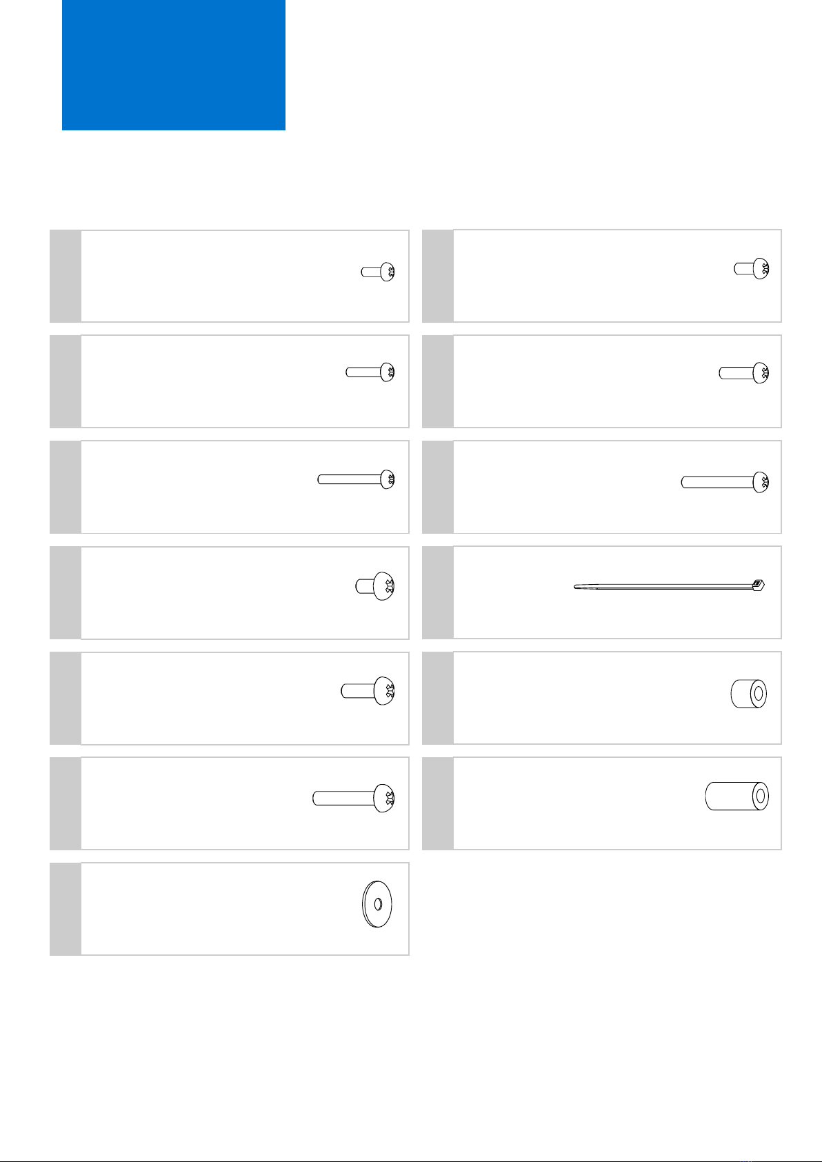
Included in the Screw Kit is a selection of screws suited to different projector models:
M4x12, M4x20, M4x35 (Parts A, C & E); M5x12, M5x20, M5x40 (Parts B, D & F); M6x12, M6x20, M6x35 (Parts G, I & K)
If you are using the M4 or M5 screws to fasten your projector to the Mounting Arms, make sure you use the included washers
(Part M) Some projectors may have irregular shapes that make the shorter screws unsuitable for mounting to the underside of
the projector. Use one of the longer screws instead, in combination with either the Short or Long Nylon Spacers (J & L) provided.

Page 6
DIAGRAM
Spider 70 Diagram
Arm
Ball Stud
Ceiling Mount Plate
Arm Mount Plate
Ball Stud Bolt
Slotted Lock Ring
Ball Stud Thread Hole
Ball Stud Thread

1. Determine where on the ceiling you wish to install the projector mount.
Keep in mind that the top of the projector will be approximately 95mm below
the ceiling, so locate the mount a suitable distance from the projector screen,
taking the throw of the projector into account.
2. Loosen the three ball stud bolts until the ball stud can be removed from the
slotted lock ring. Remove the ball stud from the lock ring through the slot in
the lock ring.
3. The Spider 70 will now be separated into two pieces as shown below.
4. Once you have located a suitable spot on the ceiling, place the ceiling mount
plate flush against the ceiling, and mark the four holes using the ceiling mount
plate as a stencil.
5. Remove the ceiling mount plate from against the ceiling.
INSTALLATION
Installation Procedure
Page 7
Top Piece
Bottom Piece

6. Optional: If you wish to be able to fine tune the direction the projector is
facing after installation, you will need to drill out a larger hole in the ceiling to
accommodate the ball stud thread. The larger hole is located in the centre of
the four smaller holes, and is called the “Ball Stud Thread Hole” on the
diagram included in this manual. Drill the central hole using a drill bit that is a
slightly larger diameter than the Ball Stud Thread. This will allow the Ball Stud
Thread to be screwed into the ceiling after installation, which gives you finer
control over the direction the projector is facing.
7. Drill the four holes in the ceiling which were marked in the previous steps. The
diameter of the holes will depend on what fasteners you plan on using to fix
the ceiling mount plate to the ceiling. Use fasteners/screws appropriate to the
type of ceiling you are fastening to (ie. Concrete, wood, etc)
8. Fasten the ceiling mount plate to the ceiling using four fasteners suitable for
the ceiling you are attaching it to.
9. Place the lower portion of the Spider 70 on top of the projector you are using.
If the mounting holes on the projector do not line up with the Spider Arms, you
may have to adjust the direction the Spider Arms are facing.
INSTALLATION
Installation Procedure (Continued)
Page 8

10.Fasten the Spider Arms to the projector using the mounting screws that came
with the projector. If none were supplied with the projector, you will need to
find suitable screws for your model and use them.
11.Once the projector is securely fastened to the Spider Arms, reconnect the
lower portion of the Spider 70 to the upper portion which was fastened to the
ceiling in step 8. You will need to slot the Ball Stud Thread through the slot in
the Slotted Lock ring, and tighten up the three bolts on the Slotted Lock ring to
secure the projector into place. The Ball Stud can be pivoted so the projector is
facing up to 20 degrees towards the floor so some adjustment may be required
for optimal positioning.
12.Optional: If you need to fine tune the direction the projector is facing, and you
followed Step 6 of this guide, you may loosen the bolt at the top of the Ball
Stud Thread and turn the Ball Stud clockwise to change the direction it is
facing.
INSTALLATION
Installation Procedure (Continued)
Page 9

SPECIFICATIONS
Schematic Diagram
Page 10

Warranty and Returns Policy
RETURNS POLICY
At Ultralift Australia Pty Ltd, we take pride in the fact that our products are of the highest quality.
Because of this, we offer the following programs to ensure your satisfaction.
ULTRALIFT 2 YEAR WARRANTY
1. The product is warranted for 24 months from the date of invoice. Subject to the conditions of
this warranty, Ultralift Australia or an authorised installer will perform necessary service on the
product without charge for parts or labour if, in the opinion of Ultralift Australia, the product is
found to be faulty within the warranty period.
2. This warranty only applies to Ultralift Australia products when purchased from Ultralift
Australia or from an authorised dealer.
3. This warranty only applies if the product has been installed and used in accordance with the
manufacturer’s recommendations (as noted in the instruction manual) under normal use and
reasonable care (in the opinion of Ultralift Australia). The warranty covers normal domestic,
commercial or educational use only. It does not cover damage, malfunction, neglect, build-up
of dirt or dust, abuse, maladjustment of customer controls, mains supply problems,
thunderstorm activity, infestation by insects or vermin, tampering or repair by unauthorised
persons (including unauthorized alterations), exposure to abnormally corrosive conditions or
any foreign object or matter having entered the product.
4. If warranty service is required you should:
Contact your installer for advice on how to rectify the issue.
If this does not solve the problem please call Ultralift Australia on 61 3 9459 0873 for
advice.
If the device requires service, return the product to Ultralift Australia for repair.
Please Note: Freight and insurance to and / or from the location of the device must be
arranged by you. Please ensure that items returned are packed in an appropriate
manner.
5. The warranties hereby conferred do not extend to, and exclude, any costs associated with the
installation, de-installation or re-installation of a product. This includes costs related to the
mounting, de-mounting or re-mounting of any screen, (and any other ancillary devices),
delivery, handling, freighting, transportation or insurance of the product or any part thereof or
replacement to such installation, deinstallation, re-installation or transit.
Ultralift Australia Pty Ltd
Email: [email protected]
Web: www.ultraliftaustralia.com.au
Phone: 61 3 9459 0873 Fax: 61 3 9457 6686
10 Vernon Ave, Heidelberg Heights VIC 3081 Australia
Page 1 of 2

RETURNS POLICY
OUR HASSLE FREE RETURN PROGRAM
Our thirty day return program means you may return your purchase, excluding special orders and/
or non stock products, to us should you be dissatisfied with your purchase within thirty days of
receipt of the product. You must return the item(s) to us by 2nd day freight, insured for full value,
with original packaging, documentation, all manuals and accessories. Freight charges, for delivery
and return and related insurance charges, will not be refunded or credited. There will also be a
restocking fee of 15% of the purchase price.
CONDITIONS OF RETURNED ITEMS
Do not write on the box. If the box is written on, the returned product will be refused. Be in the
original shipping carton with all original packing material. Include all accessories in their original
wrapping/packing material. The actual replacement cost for missing items will be deducted from
your refund/credit. Include all manuals, warranty information and instructions. The actual
replacement cost for missing items will be deducted from your refund/credit.
DEFECTIVE OR D.O.A. PROGRAM
In the case of defective or D.O.A. product(s), no charges will apply. Our Customer Service team
must be notified within 30 days of your invoice date if there are any problems with any item(s)
upon receipt. Defective or D.O.A. merchandise will be repaired and returned or exchanged for the
same make or model.
FOR ITEMS DAMAGED DURING TRANSPORT
Ultralift Australia Pty Ltd endeavours to use reputable carriers, but occasionally shipping damage
does occur. Resolving the problem of transit damage or loss depends on the cooperation of all
parties. In the event of damage or loss it is imperative that you follow these guidelines:
1. Inspect all shipments upon arrival. If damage or loss is apparent upon delivery, do not accept
the goods and do not sign for damaged or missing cartons. If you do accept the goods, keep all
packing materials and boxes with the damaged product.
2. Immediately advise Ultralift Australia of all damages or problems with the delivery of goods.
REFUNDS
Established Account:
A full refund will not be issued if the purchaser’s account has an open balance. A credit memo will
be issued, and credit will be applied first to the invoice on which the products were purchased,
then to any other open invoices on the account, beginning with the oldest invoice.
Credit Card / EFT:
All refunds for purchases made by Credit Card/EFT will be issued as a credit to that same account
within a reasonable period of time after inspection of returned products.
Cheque:
All refunds for purchases paid by cheque, whether prepaid, C.O.D., or account, will be paid by
cheque within a reasonable amount of time, after inspection of returned products.
Ultralift Australia Pty Ltd
Email: [email protected]
Web: www.ultraliftaustralia.com.au
Phone: 61 3 9459 0873 Fax: 61 3 9457 6686
10 Vernon Ave, Heidelberg Heights VIC 3081 Australia
Page 2 of 2

By using the information in this manual, you agree to the following terms of use.
The information disclosed in this manual, including all designs and related materials, is
the valuable property of Ultralift Australia Pty. Ltd. The information is subject to change
at any time without notice. Ultralift Australia Pty. Ltd. reserves the right to amend, modify
or replace these terms at any time and without further notice in future revisions of this
manual.
Ultralift Australia Pty. Ltd. does not guarantee or warranty that the product will
operate as described in all applications, environments and situations, such as those the
product was not designed to operate in. The warranty provided with the product at the
time of purchase covers the use of the product in some applications, environments and
situations - those it was specifically designed for. (hereafter referred to as “Intended
Use”) The product(s) discussed in this manual are warranted in accordance with the
terms of the Warranty Statement accompanying each product.
Every effort has been made to ensure that the information and content in this manual is
accurate, up-to-date and reliable, but Ultralift Australia Pty. Ltd. and its subcontractors
cannot be held responsible for inaccuracies, errors or omissions. Use of the product in
accordance with information from this manual is undertaken solely at the installer’s,
dealer’s and user's own risk. No warranty or guarantee is provided for this manual or the
contents therein.
This product should only be installed by a qualified technician. Technicians are advised to
take caution when installing this product, in accordance with the Safety Warning at the
beginning of the manual. Persons, Installers, Technicians, Dealers, Tradespersons and
other Persons installing this product take full responsibility for their own personal safety
and wellbeing, as well as the safety and wellbeing of others in the immediate
environment. Those installing this product agree not to hold Ultralift Australia Pty. Ltd.
liable and responsible for death, injury, impairment or other health issues that may arise
from installing this product, as far as is it lawful for Ultralift Australia Pty. Ltd. to do so
under the laws of the State of Victoria, Australia and the Commonwealth of Australia.
All products, brands, or trade names used in this publication which are not the
trademarks or registered trademarks of Ultralift Australia Pty. Ltd. are trademarks or
registered trademarks of their respective trademark owners.
This agreement shall be governed by and interpreted in accordance with the laws of the
State of Victoria, Australia and the Commonwealth of Australia.
LEGAL
Legal Notice & Liability Disclaimer
Page 13

Ultralift Australia Pty Ltd
10 Vernon Ave, Heidelberg Heights VIC 3081 Australia
Email: sales@ultraliftaustralia.com.au
Web: www.ultraliftaustralia.com.au
Phone: 61 3 9459 0873
Fax: 61 3 9457 6686
THANKYOU FOR CHOOSING
Table of contents