www.ultravation.com
3
Electrical Requirement:
Always follow all local electrical codes when
installing our water treatment equipment.
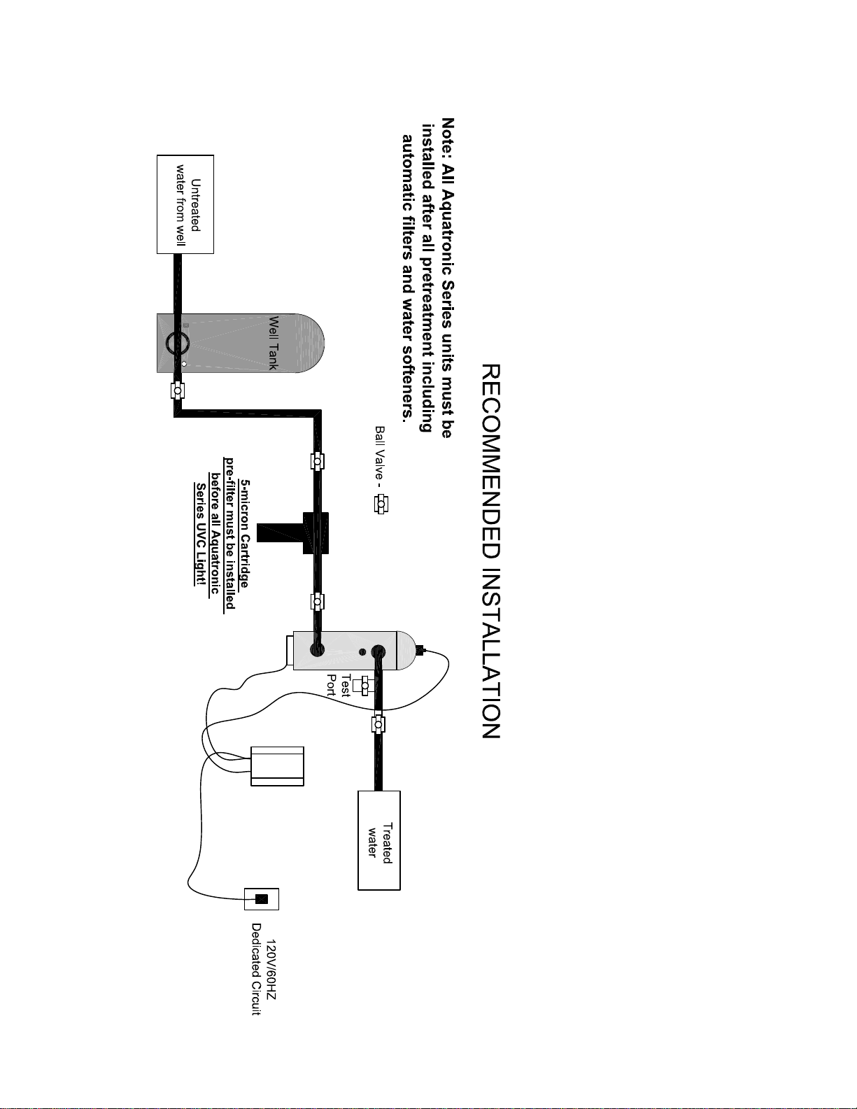
1. Provide a properly grounded 115V/60 HZ dedicated
electrical outlet. Avoid using outlets that are
switch controlled.
2. Maximum amperage required is 5 amps.
3. Make sure the electrical service provides power 24
hours per day. We recommend installing a surge
protector to protect unit from power surges, which
are not covered by warranty.
!! DO NOT UNDER ANY CIRCUMSTANCE WIRE THE
UV UNIT TO THE WELL PUMP SWITCH OR WELL
PUMP ELECTRICAL SUPPLY!!!
Power Supply Installation:
1. Choose a wall placement that is dry and clear of all
piping and metal objects, and within 4 feet of the UV
vessel and the electrical outlet.
2. Remove cover from power supply for mounting.
3. Secure power supply to wall with screws. (not
provided)
4. Properly ground the power pack to the UV vessel.
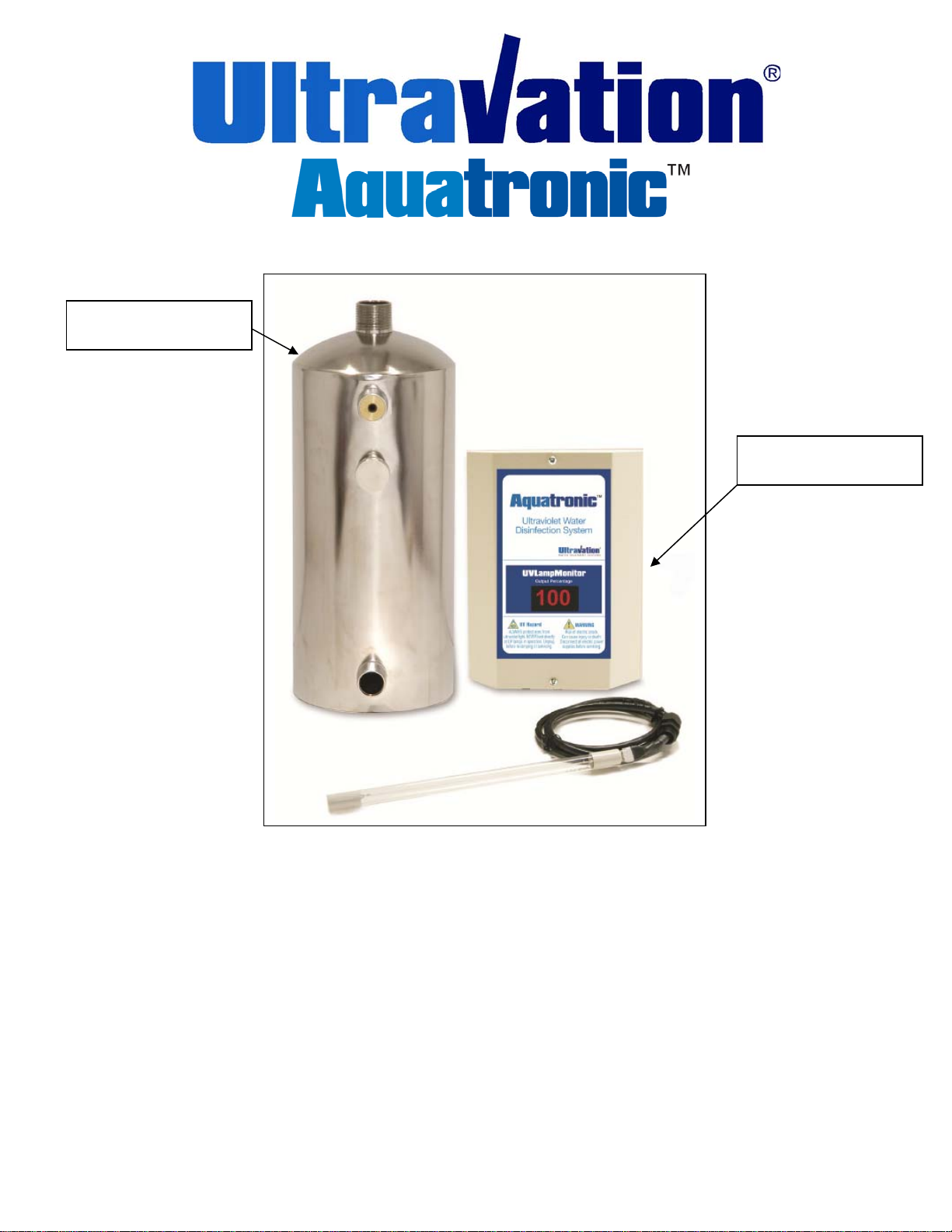
Quartz and O-ring Installation:
1. Wipe the quartz sleeve with household alcohol to
remove dirt, oil and fingerprints.
2. Carefully place the quartz sleeve into the top opening
of the vessel.
3. Lubricate the o-ring with silicone (which is supplied)
then place the o-ring over the top of the quartz
sleeve.
4. Hand-tighten the clear gland nut onto the nipple
located on the top of the vessel. DO NOT OVER
TIGHTEN OR THE QUARTZ SLEEVE MAY
SHATTER. WHEN OPERATING, THE CLEAR
GLAND NUT WILL GLOW BLUE.
SS Vessel Installation:
1. The ultraviolet unit is designed to be installed in a
vertical position. The unit is supplied with (2)
brackets to support the unit.
NOTE: The upper bracket has a grounding lug
attached to it.
2. Place the top bracket (larger one) over the nipple
located at the top of the vessel. The end of the
bracket with the three holes should be facing up
towards the top of the vessel.
3. Tighten the gray PVC ring onto the nipple. This
will compress down onto the top of bracket.
4. Attach the smaller bracket to the bottom of the
vessel. The bracket has a clip type fastener that
attaches to the bottom rim of the vessel. The end
of the bracket with the three holes should be
facing down towards the bottom of the vessel.
5. Secure the top bracket to a wall by using three
appropriate screws or fasteners (not provided).
Be sure to leave plenty of clearance above
vessel for servicing the quartz tube and
germicidal lamp.
6. Secure the bottom bracket to the wall by using
three screws or fasteners (not provided).
7. Use quality unions and ball valves on the inlet and
outlet for servicing the unit. See Page 7 for a
typical installation piping layout. If sweat fittings
are used, be sure soldering is done in such a
manner as not to allow heat to reach the UV
vessel. If Schedule 80 PVC or CPVC is used,
make sure to follow the proper primer and solvent
instructions.
8. Pipe the inlet into the bottom nipple and the
outlet into the top nipple on the UV vessel. There
is an internal flow restrictor in the outlet nipple of
all units. It is recommended you install a boiler
drain on the outlet piping of the unit for
bacteria testing.