Ultravation UVS Series User manual

UVS & UVE REMOTE LAMP AIR DISINFECTION SYSTEMS
OWNERS GUIDE
Models: UVS- 1200T, 1900T, 1202T, 1902T
Models: UVE- 1200T, 1900T, 1202T, 1902T
Table of Contents:
Page 2- Shipping and Packing List, Safety Precautions
Page 3-Installation Steps for remote Lamps
Page 4- Maintenance, Trouble Shooting
Page 5- Parts Description
Page 6- Replacement Parts, Warranty
LEAVE FOR HOMEOWNER
DC-IH-0214

2
Safety Precautions:
It is recommended that this unit be installed and
maintained by a trained technician:
WARNING: UV Hazard. Always protect eyes from
ultraviolet light. NEVER look at UV lamps in
operation. Unplug or disconnect power before re-
lamping or servicing.
WARNING: Severe eye damage or temporary
blinding may occur.
WARNING: DO NOT operate outside of Air Handler.
Mount lamp base to duct first.
WARNING: No openings in duct are allowed which
would give direct line-of-sight to the UV light.
In the event of accidental breakage or replacement of
the ultraviolet lamp, please ensure that the lamp is
disposed of in accordance with local and state
environmental laws regarding fluorescent lamps
containing mercury.
Notice:
All wiring inside of the duct or air handling system in
direct line of site of the UV lamp must be shielded with
aluminum foil tape or equivalent non-combustible
material. When installing this unit, select a mounting
location that prevents ultraviolet light exposure to
plastic flexible duct liner or other plastic components
with unknown resistance to ultraviolet light. Ultraviolet
light may cause color shift or structural degradation of
plastic HVAC components
Shipping and Packaging List:
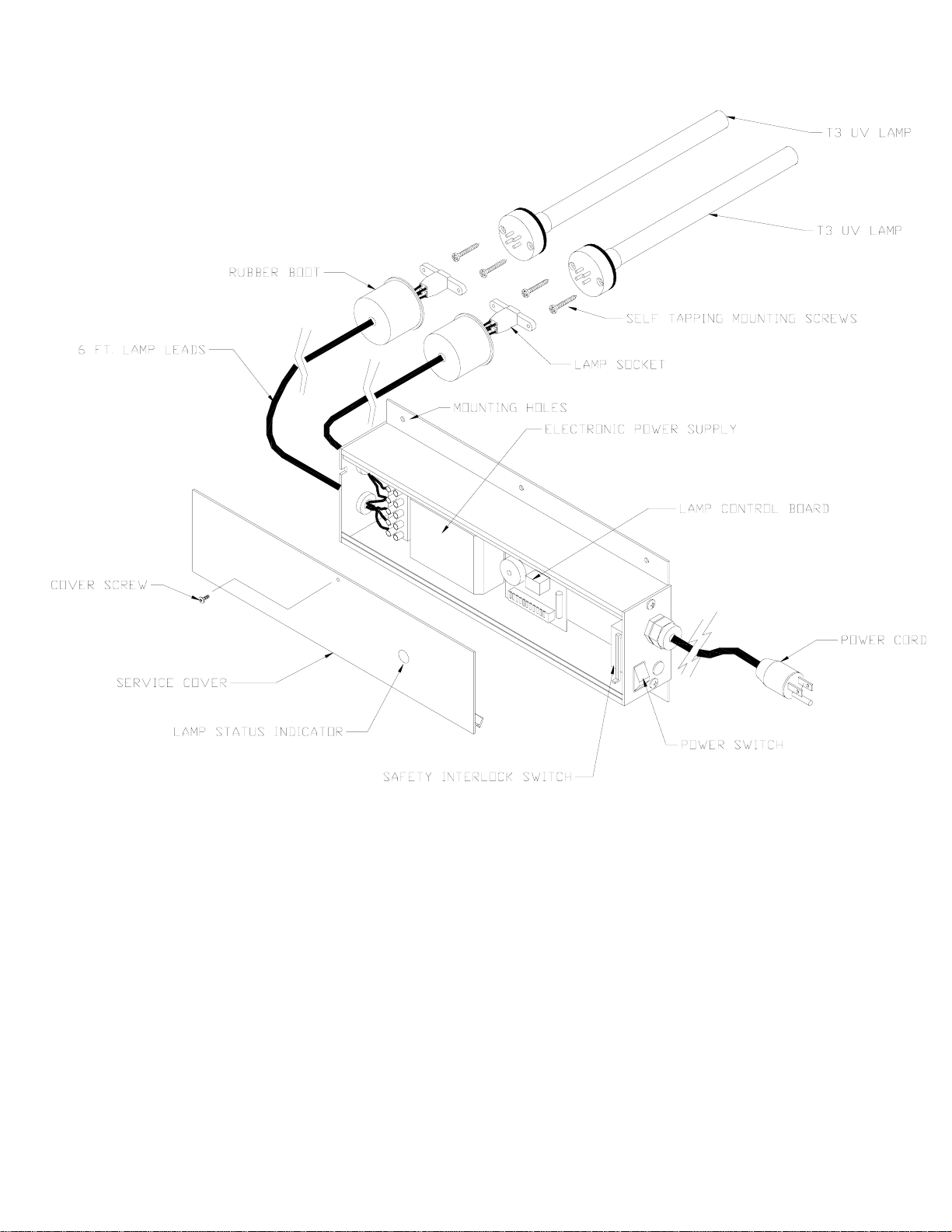
•UVS or UVE Electrical Housing
•6- ¾ inch 5/16 self tapping sheet metal screws
•Warning Label
•Residential Warranty Card
UVS- 1200T, 1202T, 1900T, 1902T
•**1200T and 1900T Series- 1 12” or 17” T3
Lamp
•**1202T and 1902T Series- 2 12” or 17” T3
Lamp
•*8 or 12 T3 Lamp mounting plate mounting
screws
•*2 or 4 T3 Lamp mounting screws
•*1 or 2 T3 Lamp mounting plate
UVE- 1200T, 1202T, 1900T, 1902T
•**1200T and 1900T Series- One 12” or 17” T3
Lamp
•**1202T and 1902T Series- Two 12” or 17” T3
Lamp
•*1 or 2 T3 Lamp mounting plate w/ mounting
Hardware
UVE- 1224T, 12242T, 1924T, 19242T
•**1224T and 1924T Series- One 12” or 17” T3
Lamp
•**12242T and 19242T Series- Two 12” or 17”
T3 Lamp
•*1 or 2 T3 Lamp mounting plate w/ mounting
Hardware
•*1 or 2 T3 Lamp mounting bracket assembly
* Number depends on 1 or 2 T3 Lamps
** T3 Lamp gasket included

3
Installation Steps for Remote UVC Units:
1. Determine a suitable location to install unit housing.
Mounting location should be of sufficient strength as to
support the unit; otherwise reinforcement of the ductwork
may be necessary. Lift into place against ductwork. Fasten
unit in place with four or six self- tapping screws (supplied).
2.Select location for UV lamp module(s). Drill a 1” hole.
Insert UV lamp module into hole. Attach to HVAC system
with 2 self-drilling screws (provided).
3.Plug plastic lamp connector onto installed UV lamp
module. Be sure the connector is pushed fully onto the
lamp.
3a. If unit is a UVE Model, please skip step #4
4. Before power is applied to the unit: Complete step1 if
battery is not in holder.
1. Insert coin battery (+ side out, see drawing) into
battery holder on circuit
board, LED should turn RED for approx. 15
seconds.
*If LED does not turn RED rotate battery around
while in holder.
2.Depress black RESET button (hold down for 10
sec.) on circuit board,
the LED should turn GREEN while the button is
depressed.
3. Release the black RESET button and the LED
should return to RED.
You now have set the internal clock to zero insuring an
accurate measurement of lamp life operating hours.
NOTE: When replacing lamps after 9000 hours of
operation (shut off power to the unit) only steps 2 & 3 will
be required to set the clock back to 0 to begin counting the
operating hours of the new lamp.
5. Plug in unit/ make electrical connections. THIS SHOULD
BE DONE IN ACCORDANCE WITH ALL STATE AND
LOCAL ELECTRICAL AND BUILDING CODES.
6. Turn on unit and inspect operation.
Remote Lamp
Installation
LED
POSITIVE SIDE OF COIN
BATTERY THIS DIRECTION
UVLAMPMONITOR
CIRCUIT BOARD
RESET
CR2032
ELOH0031
BATTERY HOLDER
UVS Battery
Location

4
UV Lamp Monitor: (UVS SERIES ONLY)
LED
Color Audible
Visual Alarm Unit
Status
Green
No audible
OK
Solid Red
No Audible
replace lamp within 30 days
Flashing Red
(Every 5 seconds) Beep every
3 Minutes
Lamp has exceeded 1 yr. of operation, replace lamps and reset
Pulsing Red
(Every 1 second) Beep every
1 second UV lamp(s) are not lit (verify if possible)
Please contact your local dealer or Ultravation directly for replacement lamps and batteries
There are NO user serviceable parts inside. Refer servicing to qualified service personnel.
Maintenance:
Maintenance typically consists of an annual replacement of
the ultraviolet lamps.
UV lamps undergo a photochemical process during
operation. This slowly reduces the amount of UV light
generated to disinfect against airborne pathogens.
When installing new lamps, ensure that the lamp glass is
free from any fingerprints or debris, as this may alter the
path of the UV energy. Use rubbing alcohol and a dry cloth
to remove any surface contaminants.
Troubleshooting:
The Ultravation air disinfection equipment is designed to
provide many years of trouble free operation. In the unlikely
event of a problem, please contact your local dealer or
Ultravation directly. Before calling for service, you should
have your Model No; Serial No; Manufacturing Date;
If you are troubleshooting the unit, check the following:
It is recommended that this unit be installed and
maintained by a trained technician.
Never perform maintenance on the UV unit without
disconnecting power.
Verify the unit has power (120-277 volt)
Power switch is in the ON position
Safety interlock switch is depressed by the cover
Lamps are securely plugged into their sockets, no loose
wires.
The electronic circuit of a 2-lamp system only operates
when both lamps are operating.
Verify fuses are not blown, visually inspect or perform a
continuity test of the fuse.
Verify what signal if any the UV Lamp Monitor LED is
emitting. (See below).
Check Battery Voltage, should read about 2.8 -3.0 V (UVS
only)
DC lower voltages can cause erratic LED readings
Verify if in fact the UV lamps are on or off. Do not look at
the UV light without proper eye protection.
If possible try new lamps in Unit to see if they light.
NOTE: If one lamp does not light in a 2 lamp system
neither lamp will light.

5
PART DESCRIPTIONS:

6
Power Consumption and Replacement Part Numbers:
Model Number of
Lamps Power
Consumption Lamp Replacement
Part #
UVE-1200 1-12 Inch 19 Watts AS-IH-1001
UVE-1202 2-12 Inch 38 Watts AS-IH-1001
UVE-1900 1-17 Inch 29 Watts AS-IH-1003
UVE-1902 2-17 Inch 57 Watts AS-IH-1003
UVS-1200 1-12 Inch 19 Watts AS-IH-1001
UVS-1202 2-12 Inch 38 Watts AS-IH-1001
UVS-1900 1-17 Inch 29 Watts AS-IH-1003
UVS-1902 2-17 Inch 57 Watts AS-IH-1003
UVE-1200T 1-12 Inch 19 Watts AS-IH-1001
UVE-1202T 2-12 Inch 38 Watts AS-IH-1001
UVE-1900T 1-17 Inch 29 Watts AS-IH-1003
UVE-1902T 2-17 Inch 57 Watts AS-IH-1003
UVS-1200T 1-12 Inch 19 Watts AS-IH-1001
UVS-1202T 2-12 Inch 38 Watts AS-IH-1001
UVS-1900T 1-17 Inch 29 Watts AS-IH-1003
UVS-1902T 2-17 Inch 57 Watts AS-IH-1003
UVE 5 Amp Fuse EL-PP-0044
UVS Battery EL-PP-0030
Warranty:
Ultravation warrants this product against any defects in material or workmanship for a period of 10 years after
date of consumer purchase, with the exception of the Ultraviolet Lamp(s), which are warranted for a period of one
year after date of consumer purchase.
This warranty does not include damage to the unit from accident, misuse or improper installation.
If this product should become defective during the warranty period, Ultravation will repair or elect to replace the
product free of charge.
Ultravation will return repaired or replaced warranted products pre-paid, provided that the product was delivered
pre-paid.
Ultravation shall have no responsibilities for charges incurred by the customer for installation or removal of
warranted items.
Liability is limited only to the replacement or repair of this product
This warranty gives you specific legal rights, and you may also have other rights, which vary from state to state.
All returns must be accompanied by a return authorization number, which may be obtained by contacting
Ultravation, Inc.
Ultravation, Inc.~ P.O. Box 234 ~ 218 Jones Drive ~ Brandon, Vermont 05733
Phone: 802-247-0034 ~ Fax: 802-247-0033 ~ www.ultravation.com
This manual suits for next models
9
Table of contents
Other Ultravation Laboratory Equipment manuals
Popular Laboratory Equipment manuals by other brands

ThermoFisher Scientific
ThermoFisher Scientific QuantStudio Series user guide

wtw
wtw SenTix 51 operating manual

Philips
Philips Avent SCF293 manual

Eisco
Eisco PH0849 instruction manual

ThermoFisher Scientific
ThermoFisher Scientific QuantStudio 12K Flex OpenArray AccuFill... user guide

Bio-Works
Bio-Works BabyBio S instructions