Ultraviolet Sysrtems Inc. Ultra UV2 User manual

1555 Detrick Ave. Deland, Florida 32724-2014
Toll Free: 1.866.649.5551 Phone: 407.600.5751
Pool, Spa & Pond
Water Sanitizer 4BJ1
EPA Registered
#084221-AZ-001
INSTALLATION &
OPERATIONS MANUAL
IMPORTANT SAFETY INSTRUCTIONS: READ
COMPLETELY BEFORE PROCEEDING.
When using this electrical equipment, basic safety
precautions should always be followed, including the
following:
• Follow all applicable electrical codes.
•Turn off power at main source before making any electrical connections or servicing the unit.
•To reduce the risk of electric shock, injury or death disconnect unit from power supply
• Follow the instructions or risk of serious injury or death could occur!
UV EXPOSURE & PROTECTION:
UV-A and UV-B radiation can have adverse short and long term effects on the eyes and skin. Never
look directly at a UV lamp that is connected to a power source. Avoid UV skin exposure at all times.
WARNING
To Installers: Read and follow these
instructions. Give these instructions to the
facility owner to keep for future reference.
Follow all codes and regulations that apply to the design, installation and use
of suction outlet fittings.
NOTICE

2
PLEASE REVIEW THE OWNER’S MANUAL AND INSTALLATION GUIDE IN ITS ENTIRETY AND
HEED ALL SAFETY INFORMATION. Failure to follow these instructions and warnings can result in
DEATH OR SERIOUS INJURY.
DANGER DANGER indicates a hazardous situation which,
if not avoided, will result in death or serious injury.
WARNING WARNING indicates a hazardous situation which,
if not avoided, could result in death or serious injury.
CAUTION CAUTION indicates a hazardous situation which,
if not avoided, could result in minor or moderate injury.
NOTICE NOTICE is used to address practices not related to physical
injury.
Signal Words and Symbols Used In This Manual
This Owner’s Manual and Installation Guide contains specific precautions and symbols to identify safety-
related information. You will find DANGER, CAUTION, WARNING and NOTICE symbols which require
special attention. Please read them carefully and follow these precautions as indicated! They will explain
how to avoid hazards that may endanger you or persons using or maintaining your pool or spa.
IMPORTANT SAFETY INSTRUCTIONS
SAVE THESE INSTRUCTIONS

3
Tabl e of Contents
Welcome ............................................................................................................................................................................4
General Product Information.........................................................................................................................................4
Ultra UV2 System Sizing ...............................................................................................................................................4
Pond Sizing Considerations..........................................................................................................................................4
Pond Sizing Chart ............................................................................................................................................................5
Pool, Spa, Fountain, Water Feature and Water Fall Sizing Chart .....................................................................5
First Step In Starting Your Installation........................................................................................................................5
Locating The Ultra UV2 Unit.........................................................................................................................................6
Installing Inlet/Outlet Unions.........................................................................................................................................6
Mounting The UV Unit On A Solid Base...................................................................................................................6
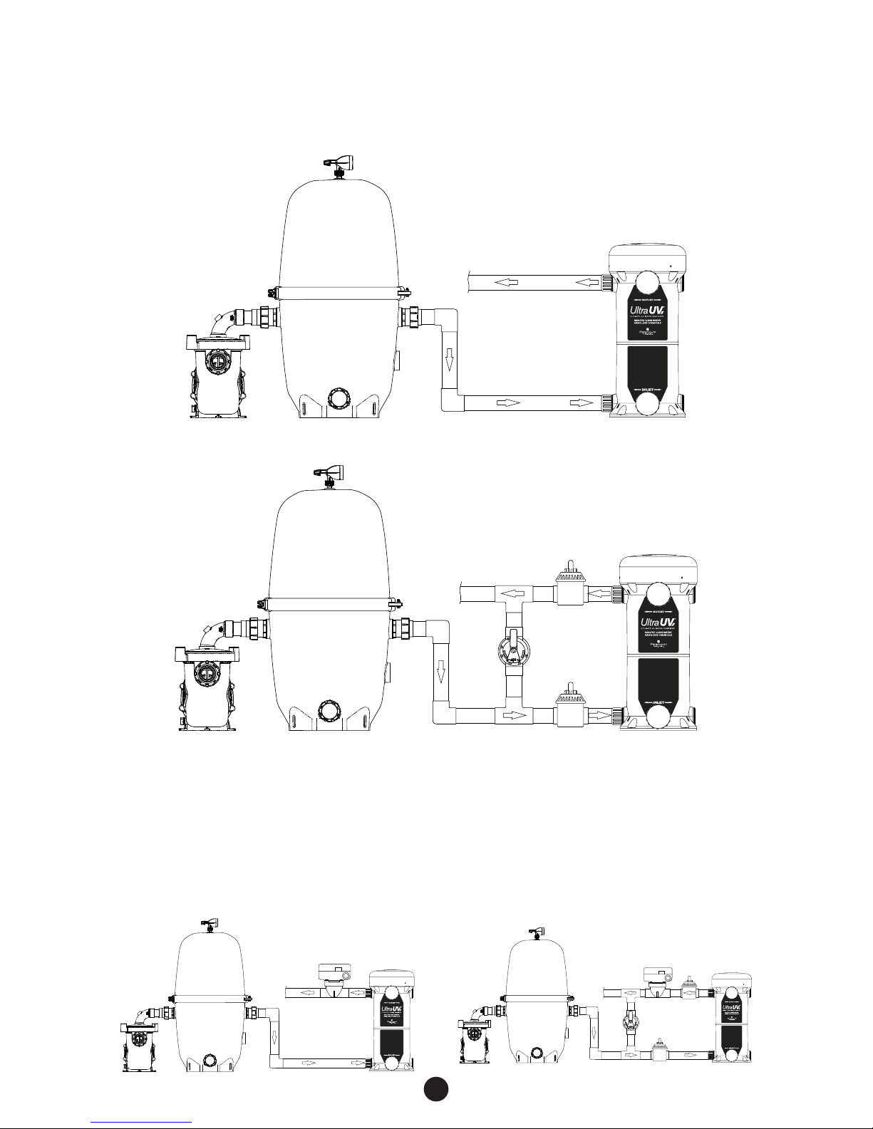
Plumbing The Ultra UV2 Unit........................................................................................................................................6
Typi cal Plumbing Without and with b ypass ............................................................................................................7
Parallel Plumbing Without and with bypass ..........................................................................................................8
Multiple port Plumbing FOR 3 LAMP UNITS Without and with bypass .....................................................9
Gluing Piping To The UV Unit....................................................................................................................................10
Providing Electrical Power To The Ultra UV2 Unit...............................................................................................10
Electrical Bonding (Grounding)................................................................................................................................10
System Start-Up ........................................................................................................................................................... 11
Connecting Pressure Switch.....................................................................................................................................11
Water Chemical Balance ............................................................................................................................................11
Upgrading The Output Of The
Ultra UV2 Unit.................................................................................................................................................................11
Consumer Operating Instructions............................................................................................................................12
Quartz Tube Maintenance...........................................................................................................................................12
Scheduled UV Lamp(s) Replacement....................................................................................................................14
Lamp Replacement Procedure.................................................................................................................................14
Normal Operation .........................................................................................................................................................15
Bypass Operation ........................................................................................................................................................15
Winterization Of Your Ultra UV2 Unit .....................................................................................................................15
Troubleshooting .............................................................................................................................................................16
Ultra UV2 Part Numbers .............................................................................................................................................18

4
WELCOME
The Ultra UV2 unit is designed for use in swimming pools, spas, fountains, water features, waterfalls, fish
ponds and the like. It is not designed for use in potable (drinking) water installations. Use of this product
in applications other than those indicated above will void your warranty and could be harmful to your
health or the health of others.
GENERAL PRODUCT INFORMATION
Water circulates through the Ultra UV2 chamber and around the quartz tube where the UV-C lamp(s) (1
to 3 lamps depending on the model) are housed. The UV-C lamp emits a light wave spectrum (253.7 nm
wavelength) to immediately inactivate 99.9% of micro-organisms such as Crypto, Giardia, other single
celled waterborne microorganisms and algae which are resistant to chlorine. This provides a cleaner,
clearer swimming environment with zero harmful by-products and dramatically reduces the amount of
chlorine needed to maintain an adequate level of residual sanitizer. The Ultra UV2 unit has been sized to
produce these important UV rays in the same intensity as is required for Class A potable drinking water,
which is 30,000 micro watts/cm2 (30 mJ). Confirm the size unit your application needs by using the
sizing charts on page 5, to obtain the proper maximum system killing power.
Please note the minimum and maximum flow rates for each Ultra UV2 lamp configurations.
CAUTION DO NOT USE THIS UNIT FOR POTABLE (DRINKING)
WATER SANITATION.
ULTRA UV2 SYSTEM SIZING
In order to ensure that your Ultra UV2 unit functions with the proper water exposure time to achieve the
desired water sanitation, it is important to provide the proper water flow rate through the Ultra UV2 unit. If
water passes through the unit too quickly, the microorganism’s exposure time to the UV lamp(s) produced
rays will not be sufficient to obtain the desired rate of sanitation. Please note that the minimum
posted flow rate must be met or exceeded to ensure proper system performance. The water
flow rate through the UV unit is governed by the piping of your water vessel and the size and output of
your circulation pump. Consideration to the application for the UV unit must be determined. Fish ponds,
as an example, have different requirements than swimming pools, spas, water features, fountains, or
waterfalls, as noted elsewhere in this manual.
POND SIZING CONSIDERATIONS
Most fish pond experts agree that there is no simple or set formula for the sizing of circulation pumps and
UV systems for fish ponds. The best advice is to consult a fish pond expert to determine what the flow
rate for your pond should be, and use the appropriate sized Ultra UV2 for that flow rate see “Fig. 1” on
page 5.

5
FIRST STEP IN STARTING YOUR INSTALLATION
Inspect the Ultra UV2 unit for damage, paying close attention to
the quartz tube.
NOTICE
POND SIZING CHART
Fig. 1
See Chart Below.
Ultra UV2 Part Number
Minimum
Flow Rate
(GPM) /
(m3/hr)
Maximum
Flow Rate
(GPM) /
(m3/hr)
Max Pond
Volume
2 Hr.
Turnover
(GPM) /
(m3/hr)
Max Pond
Volume
3 Hr.
Turn o v er
(GPM) /
(m3/hr)
Minimum
Operating
Pressure
(psi) / (bar)
Maximum
Operating
Pressure
(psi) / (bar)
004-422-2025-00
230V w/ 1 UV-C Lamp
004-422-2021-00
120V w/ 1 UV-C Lamp
10 / 2.27 46 / 10.4 5520 /
20.9
8280 /
31.3 5 / .345 50 / 3.45
004-422-2026-00
230V w/ 2 UV-C Lamps
004-422-2022-00
120V w/ 2 UV-C Lamps
20 / 4.54 80 / 18.2 9600 /
36.3
14400 /
54.5 5 / .345 50 / 3.45
004-422-2027-00
230V w/ 3 UV-C Lamps
004-422-2023-00
120V w/ 3 UV-C Lamps
*30 / 6.81 *130 /
*29.5
15600 /
59.1
23400 /
88.6 5 / .345 50 / 3.45
All capacities are nominal. Note: Multiple Ultra UV2 units installed in parallel can be used for flow rates
beyond those specified herein. (See page 9)
* Header size should be 2½” or 3” and split to two 2” pipe headers at the inlet and outlet connections.
(See page 10)
POOL, SPA, FOUNTAIN, WATER FEATURE AND WATER FALL SIZING CHART
Fig. 2 Swimming pools and similar water vessels are simple to calculate. See chart below.
Ultra UV2 Part Number
Minimum
Flow Rate
(GPM) /
(m3/hr)
Maximum
Flow Rate
(GPM) /
(m3/hr)
Max
Pool Volume
12 Hr.
Turn o v er
(Gallons) /
(m3/hr)
Max
Pool Volume
8 Hr.
Turn o v er
(Gallons) /
(m3/hr)
Minimum
Operating
Pressure
(psi) / (bar)
Maximum
Operating
Pressure
(psi) / (bar)
004-422-2025-00
230V w/ 1 UV-C Lamp
004-422-2021-00
120V w/ 1 UV-C Lamp
10 / 2.27 46 / 10.4 33120 /
125.4
22080 /
83.6 5 / .345 50 / 3.45
004-422-2026-00
230V w/ 2 UV-C Lamps
004-422-2022-00
120V w/ 2 UV-C Lamps
20 / 4.54 80 / 18.2 57600 /
218.0
38400 /
145.4 5 / .345 50 / 3.45
004-422-2027-00
230V w/ 3 UV-C Lamps
004-422-2023-00
120V w/ 3 UV-C Lamps
*30 / 6.81 *130 /
*29.5
93600 /
354.3
62400 /
236.2 5 / .345 50 / 3.45
All capacities are nominal Note: Multiple Ultra UV2 units installed in parallel can be used for flow rates
beyond those specified herein. (See page 9)
* Header size should be 2½" or 3" and split to two 2" pipe headers at the inlet and outlet connections.
(See page 10)

6
LOCATING THE ULTRA UV2 UNIT
Your unit can be installed indoors or
outdoors. When considering the location
for your Ultra UV2 unit, keep it close to your
power source. Check the silver product
label for the voltage of the unit. The Ultra
UV2 unit will need to be powered from
either a 120V/15A/50/60Hz or 230
V/15A/50/60Hz electrical circuit (which
MUST match the unit power requirement
noted on the silver product label on the
Ultra UV2 unit). DO NOT CONNECT TO
ELECTRICAL POWER NOT SPECIFIED
FOR YOUR UNIT. Plug in units must be
installed on a GFCI outlet. The GFCI must
be outdoor rated if installed outdoors. 230V
Ultra UV2 units can be wired for 120V or
230V.
NOTICE
DO NOT CUT OFF the plug from the 120V Ultra UV2 units
and hardwire it. This does not meet the U.L. installation
method and voids the U.L. listing.
MOUNTING THE UV UNIT ON A SOLID BASE
Before you make the permanent plumbing connections be sure the ULTRA UV2 unit is on a solid level
base making sure your plumbing connections align. After making your plumbing connections, anchor the
unit to the base using the four ¼” mounting holes. FAILURE TO PROPERLY SECURE THE UNIT
MAY CAUSE NOISE OR VIBRATION.
INSTALLING INLET/OUTLET UNIONS
The Ultra UV2 unit comes with female socket glue-in inlets and outlet openings. ABS to PVC
multipurpose glue and appropriate primer must be used to glue fittings into the ULTRA UV2 body. The
4 outlets (top) and 4 inlets (bottom) provide the most versatile piping alternatives for the installer. The
ULTRA UV2 unit comes with (2) unions (See page 19 for part numbers). Multiple inlets and outlets can
be used to the manage higher flow rates of 3 lamp units.
NOTE: The use of multiple inlets/outlets will require additional unions. Use the plugs provided with the
Ultra UV2 in the unused inlets and outlets. To install the unions onto the Ultra UV2 unit, glue and insert
the unions spigot end into the inlet and outlet opening selected. Then, using the six plugs provided, glue
the plugs into the remaining unused plumbing openings. Hand tightening the union nuts until snug is
sufficient. DO NOT OVER TIGHTEN. Over tightening may break the molded plastic parts of the unions.
Once you are confident that you have installed the inlet and outlet union halves successfully, you will be
ready to glue your plumbing into the union sockets once the Ultra UV2 unit is positioned on the mounting
surface. A 24 hour cure time is required before pressure can be applied to the Ultra UV2 unit.
Fig. 3
Power
Requirement

7
PLUMBING THE ULTRA UV2 UNIT
All plumbing methods are illustrated with and without the bypass option. Your Ultra UV2 unit will need
to be plumbed into the circulation system. The Ultra UV2 unit must be installed directly after the
filter. Installing a bypass is not recommended. The only reasons for installing an Ultra UV2 bypass:
1. To allow for removal of the UV unit, while still allowing the system to operate with water flowing through
the bypass. 2. If system pressure testing above 50 psi is required (max Ultra UV2 pressure is 50 psi/ 3.45
bar). The acceptable reasons for removal include winterization, servicing, off site repairs and replacement.
If a bypass is required it must be installed & operated per instructions on pages 9 - 10.
Before bypassing the Ultra UV2 for removal, turn off all pumps and allow the pool system’s pressure to
drop to zero.
AN IMPROPERLY USED BYPASS INSTALLATION MAY NOT MEET THE
MINIMUM REQUIRED FLOW RATE AND COULD POTENTIALLY DAMAGE
THE ULTRA UV2 UNIT.
Do not plumb the Ultra UV2 with a bypass unless absolutely
needed. Failure to follow the instructions can result in damage
to the Ultra UV2 that is not covered by the warranty.
NOTICE
Turn o ff the power at th e main source befor e disconnect ing or
connecting the Ultra UV2.
DANGER

8
TYPICAL PLUMBING WITHOUT AND WITH BYPASS
The inlet(s) is at the bottom of the unit and the outlet(s) at the top. The maximum operating pressure for
the Ultra UV2 is 50 PSI / 3.45 BAR. The minimum operating pressure is 5 PSI / .345 BAR. Please refer
to the silver label on the unit for max. operating pressure.
Filter
Pump
Without bypass (RECOMMENDED)
Fig. 4
Filter
To Heater
or Pool
Outlet Fully
Opened
Inlet Fully
Opened
Bypass
Fully
Closed
Pump
With bypass
Fig. 5
Installing An Optional Flow Switch If The Top Of The Unit Is Below Water Level
The pressure switch will always be on if the Ultra UV2 unit is plumbed below water level. To prevent damage
to the unit and its surroundings an optional flow switch must be installed. If the Ultra UV2 unit is plumbed on
a bypass, the optional 2 inch Flow Switch (part #004-402-0010-00 for 220v or part #004-421-3824-00 for
120v), must be on the outlet side of the Ultra UV2 unit and plumbed after the two way valve and before the tee
into the return line. Please refer to the instructions supplied with the flow switch for plumbing and wiring.
Flow Switch
Filter
To Heater
or Pool
Pump
No bypass with optional flow switch
Fig. 6
Filter
To Heater
or Pool
Pump
Flow Switch Outlet Fully
Opened
Inlet Fully
Opened
Bypass
Fully
Closed
Bypass with optional flow switch
Fig. 7

9
PARALLEL PLUMBING WITHOUT AND WITH BYPASS
Plumbing Ultra UV2 units in parallel for large bodies of water with high flow rates.
Without bypass (Recommended)
Fig. 8
Filter
To Heater
or Pool
Pump
With bypass
Fig. 9
Filter
To Heater
or Pool
Pump
Outlet Fully
Opened
Inlet
Fully
Opened
Inlet
Fully
Opened
Bypass
Fully
Closed
Installing An Optional Flow Switch If The Top Of The Unit Is Below Water Level
The pressure switch will always be on if the Ultra UV2 unit is plumbed below water level. To prevent damage
to the unit and its surroundings an optional flow switch must be installed. If the Ultra UV2 unit is plumbed on
a bypass, the optional 2 inch Flow Switch (part #004-402-0010-00 for 220v or part #004-421-3824-00 for
120v), must be on the outlet side of the Ultra UV2 unit and plumbed after the two way valve and before the tee
into the return line. Please refer to the instructions supplied with the flow switch for plumbing and wiring.
Filter
To Heater
or Pool
Pump
Flow Switch
No bypass with optional flow switch
Fig. 10
Filter
To Heater
or Pool
Pump
Flow Switch
Outlet Fully
Opened
Inlet
Fully
Opened
Inlet
Fully
Opened
Bypass
Fully
Closed
Bypass with optional flow switch
Fig. 11
Pump Filter
To Heater
or Pool
Inlett
Fully
Opened
Inlet
Fully
Opened
Outlet Fully
Opened
Bypass Fully
Closed
Pump Filter
To Heater
or Pool

10
MULTIPLE PORT PLUMBING FOR 3 LAMP UNITS WITHOUT AND WITH BYPASS
See figures 12 through 15. Ultra UV2 3 lamp units require 2 inlets and 2 outlets be plumbed, see page 5.
Without bypass (Recommended)
Fig. 12
Pump Filter
To Heater
or Pool
OUTIN
OUT
IN
2" PLUMBING2½" OR 3" PLUMBING 2½" OR 3" PLUMBING
With bypass
Fig. 13
Outlet Fully
Opened
Bypass Fully Closed
In Normal Operation
Pump Filter
To Heater
or Pool
OUTIN
OUT
IN
2" PLUMBING2½" OR 3" PLUMBING 2½" OR 3" PLUMBING
Installing An Optional Flow Switch If The Top Of The Unit Is Below Water Level
The pressure switch will always be on if the Ultra UV2 unit is plumbed below water level. To prevent damage
to the unit and its surroundings an optional flow switch must be installed. If the Ultra UV2 unit is plumbed on
a bypass, the optional 2 inch Flow Switch (part #004-402-0010-00 for 220v or part #004-421-3824-00 for
120v), must be on the outlet side of the Ultra UV2 unit and plumbed after the two way valve and before the tee
into the return line. Please refer to the instructions supplied with the flow switch for plumbing and wiring.
Pump Filter
To Heater
or Pool
OUTIN
OUT
IN
Flow
Switch
2" PLUMBING2½" OR 3" PLUMBING 2½" OR 3" PLUMBING
No bypass with optional flow switch
Fig.14
Outlet Fully
Opened
Pump Filter
To Heater
or Pool
Bypass Fully Closed
In Normal Operation
OUTIN
OUT
IN
Flow
Switch
2" PLUMBING2½" OR 3" PLUMBING 2½" OR 3" PLUMBING
Bypass with optional flow switch
Fig. 15

11
GLUING PIPING TO THE UV UNIT
Two Inlet/Outlet unions are supplied. Your PVC supply piping should be glued into the union tail
pieces using an appropriate primer and ABS to PVC cement. Inlet piping should be supported and
should not rest solely upon the unions, to avoid stressing or breaking the unions. Allow the glue to set
following the glue manufacturers recommendations before pressure testing. A minimum of 24 hours is
recommended. Maximum test pressure for the Ultra UV2 is 50 PSI / 3.45 BAR as noted on the silver
label on the unit. If local codes require the pressure test to be higher than the max operating pressure
on the silver label use the bypass (if the unit is plumbed with a bypass) to allow the Ultra UV2 to be only
left at or below the max operating pressure.
PROVIDING ELECTRICAL POWER TO THE ULTRA UV2 UNIT
The electrical power rating for your Ultra UV2 unit is shown on the silver label located on the outside of
the unit. (Fig. 3 on page 6) Make sure the supplied power meets the units electrical requirements.
Connecting any power than that listed on the rating label will damage the unit and will VOID your
limited warranty.
120V 50/60Hz Ultra UV2 units
If you supplied power is 120V 50/60Hz the label on your unit should match. At 120 Volts, the power
draw is 2.6 amps maximum for a 3 lamp system. This low power consumption makes operating this unit
very economical. Your Ultra UV2 120V unit is supplied with a weatherproof power cord terminating with
a 3-prong grounded NEMA plug. An outdoor rated ground fault circuit interrupter must be installed in
the electrical outlet serving the Ultra UV2 unit (subject to your local electrical codes).
WARNING Do not cut the plug off the electrical cord and connect it directly to
a 120V power source. If this is done your warranty is voided and
the U.L. listing is invalidated.
Note:
Some jurisdictions do not allow corded connections for these types of appliances. Check your local
and national electrical codes. If hard wiring is required it must be done by a licensed electrical service
person. The Ultra UV2 unit uses voltage sensitive ballast 120/230 volts. When wiring the unit 230 volts
the black and white wires are wired hot and the green wire is ground. Amp draw on a 1 or 2 lamp unit
is 120V/220V 1.3A/.56A, 3 lamp unit is 120V/220V 2.6A/1.12A. Should the electrical cord become
frayed or damaged in the future, unplug it from the power receptacle and replace it immediately.
230V 50/60Hz Ultra UV2 Units
If you supplied power is 230V 50/60Hz the label on your unit should match. A junction box with 6” of
lead wire is supplied for 230V Ultra UV2 Units.
Remember you CANNOT operate your Ultra UV2 on any power supply other than that indicated on the
units silver label.
NOTICE Have this work done by a licensed electrical technician.
ELECTRICAL BONDING (GROUNDING)
Locate the grounding lug next to the power cable (Fig. 4).
To reduce the risk of electric shock, this terminal must be
connected to the grounding means provided in the electrical
supply service panel with a continuous copper wire equivalent
in size to the circuit conductors supplying this equipment. To
reduce the risk of electric shock, connect the local common
bond grid in the area of the pool or spa to this terminal with
an insulated or bare copper conductor per national and local
codes. The electrical installation is now complete.
Fig. 4
Grounding Lug

12
SYSTEM START-UP
Do not connect the
pressure switch until
the pool is operational!
NOTICE
PRESSURE SWITCH
The Ultra UV2 unit is equipped with pressure switch
that does not allow the UV lamp(s) inside the unit to
light unless there is at least 5 PSI (0.35 BAR) inside
the Ultra UV2 reactor chamber. This will ensure that
the lamp(s) will illuminate when the Ultra UV2 unit
has water flowing through the reactor. The lamps will
only illuminate when the pressure switch senses a
minimum starting pressure of 5 psi (0.35 bar).
CONNECTING PRESSURE SWITCH
Disconnect power to the Ultra UV2 unit. Remove the
cover (Fig. 5) and locate the pressure switch and the
loose lead with the female spade connector (Fig. 6).
Connect the female spade connector to the male top
spade connector on the pressure switch (Fig. 7).
Replace the cover and restore power to the unit. Turn
on the pump and the flow should activate the switch.
The unit should be on and the lamps illuminated. Look
at the “Glow Ring” in the center of the unit to check
that all lamps are lit. If the lamps are not on, first verify
the unit is operating at 5 psi or more, then refer to the
troubleshooting section of this manual on page 17.
The filter gauge DOES
NOT indicate the
pressure in the UV unit
NOTICE
Do not look directly
at the lamps. Serious
injury will occur.
WARNING
If the Ultra UV2 does not illuminate check the following:
1. Adjust the system valves so there is flow through the
Ultra UV2 unit and not diverted to other devices.
2. The pump is producing enough pressure. If you have
a variable speed pump verify you are set at a high
enough speed to produce enough pressure to turn
on the lamps.
WATER CHEMICAL BALANCE
If you have installed your Ultra UV2 unit on any water
vessel other than fish ponds or ponds with live plants,
it is important that you check and adjust the chemical
balance of the water. The Ultra UV2 unit dramatically
reduces the need for chemical sanitizers, but a
minimum sanitizer residual must be maintained.
Pressure
Switch
Pressure
Switch
Fig. 6
Fig. 7
Fig. 5
UPGRADING THE OUTPUT OF THE
ULTRA UV2 UNIT
One of the exclusive features of the Ultra
UV2 system is the ability to increase the
UV output of the unit by adding additional
lamps. Up to two additional lamps can
be added to a single lamp system. This is
accomplished easily by adding lamps and
or adding additional ballasts and lamps.
Plumbing modifications might be required
for certain lamp upgrades

13
NORMAL OPERATION
Configuration for Ultra UV2 units installed with bypass.
During normal operation the inlet valve #2 and
outlet valve #3 should be completely open and the
bypass valve #1 should be completely closed. Any
partial opening of the bypass valve can drop the flow rate
below the required minimum and cause damage to the
Ultra UV2 unit. This instruction applies to all systems with
a single speed or with a variable speed pump. This type
of damage is not covered under the factory warranty.
WINTERIZE / SERVICE OPERATION
Configuration for Ultra UV2 units installed with bypass.
Bypass operation is used for winterization or servicing/
replacing the Ultra UV2 unit. The bypass valve #1
should be full open and the inlet valve #2 and the
outlet valve #3 should be completely closed.
WINTERIZATION OF YOUR ULTRA UV2 UNIT
If you are in a sub freezing climate you must
winterize the Ultra UV2 using either option #1 or
#2. Failure to do so will cause damage to the unit,
which is not covered under the warranty
Option #1 - Removing the unit for the winter: Turn off
the power to the unit. Disconnect the unions on the
plumbing to ensure that the unit is completely drained.
Now, with the power off, disconnect the unit from its
power source and place the drained unit in a safe
place that has a sustained temperature above freezing.
Reinstall after the temperatures are considerably above
freezing.
Option #2 - Leaving the unit in place for the winter:
Turn off the power to the unit. Disconnect the unions
on the plumbing to ensure that the unit is completely
drained. There is a cup in the bottom of your unit
that the quartz tube nests in. This cup does not drain
completely (Fig. 30). To remove the water from this
cup you must first remove the lamp array and quartz
tube Fig. 22 (See page 6). Turn the unit on its side
with the unions facing down until all of the water has
drained. Reconnect the unit, the quartz tube, lamps,
and cover. You may store the lamps and quartz tube in
a safe place.
Unions
Cup
Fig. 22
Filter
To Heater
or Pool
Pump
Bypass
Valve #1
Inlet Valve #2
Outlet Valve #3
Filter
To Heater
or Pool
Pump
Bypass
Valve #1
Inlet Valve #2
Outlet Valve #3
Fig. 20
Fig. 21

14
CONSUMER OPERATING INSTRUCTIONS
QUARTZ TUBE MAINTENANCE
Cleaning the quartz tube: The quartz tube requires cleaning
every 6 months to ensure optimum performance.
1. Turn o ff all power to th e ULTRA UV2 unit and all
other pool equipment. Unplug the unit from its power
receptacle or turn OFF the circuit breaker that is the
ULTRA UV2’s power source. Before proceeding to
step 2 allow at least 15 minutes for the lamp(s) in the
unit to cool.
Never remove the
electrical enclosure
cover without first
disconnecting the power (power source) for the Ultra
UV2 unit. Never remove the Ultra UV2 unit’s cover
without turning off the pump.
DANGER
2. Remove the three screws that secure the plastic
cover then remove Fig. 1.
Before removing
lamps you must wear
protective rubber
gloves and safety eye wear. Do not handle a hot lamp
or serious burns will occur.
WARNING
Do not touch the
glass part of the
lamp as body oils will
create hot spots & greatly shorten lamp life.
NOTICE
3. Disconnect all lamps by pressing the release tabs on
connectors and gently pulling apart. Fig. 8
4. Remove the spring clip Fig. 9. Carefully lift the old
lamp assembly, including lamp holder, from the quartz
tube Fig. 10. Do not pull excessively on the lamp
wires. Set aside the lamp assembly in a safe area to
avoid breaking or chipping.
5. Turning counter-clockwise, unscrew and remove the
round aluminum sealing nut. Fig. 11
6. Carefully lift the aluminum compression washer
from the top of the quartz tube making sure not to
lose the black gasket that cushions the edge of the
quartz tube. Fig. 12
7. Grip quartz tube with both thumbs inside and pull up.
Once the O-ring breaks free, the quartz tube should
lift out easily. Fig. 13
The quartz tube
is fragile, be sure
to handle it with
proper care and do not set it down on a hard
surface. Do not use abrasive cleaners or pads.
NOTICE
Fig. 8
Fig. 9
Fig. 11
Fig. 10
Fig. 12

15
8. Using protective rubber gloves and eye wear use
shower/tub cleaner, CLR or equivalent, or a solution
of white vinegar and water to clean the outside of the
quartz tube. Remove the O-ring from the quartz tube.
Fig. 14. If the inside of the quartz tube is moist or needs
cleaning use the same cleaning method. The quartz tube
must be completely dried and clear of residue before
reassembly.
9. Inspect the quartz tube carefully for any cracks or
chips and replace the quartz tube if any are found.
Do not use any
other O-ring
at any time for
sealing the quartz tube. Doing so can result in a
leak and possible damage to your UV unit. The
O-ring must be replaced after cleaning the quartz
tube see page 19 for part number.
NOTICE
10. All components must be completely dry and
clean. Never use any type of lube or sealing
agent. To rei nst all the q uartz tube pla ce a new
O-ring 2 inches from the top of the outside of the
quartz tube Fig. 14. Gently lower the quartz tube into
the unit until the O-ring makes contact with the top of
the black threaded sealing sleeve. Fig. 15
Note: Use a Paramount O-ring seal only.
11. Then place the aluminum compression washer
and gasket on the quartz tube. Press down on the
aluminum compression washer with an even steady
pressure. Fig. 16 This will roll the O-ring into the area
between the inside of the black threaded sleeve and
the quartz tube. Lift aluminum washer and check to
make sure it is seated evenly around the circumference
of the quartz tube. Replace aluminum washer then
screw on the quartz sealing aluminum nut to hand tight
plus ½turn.
12. Turn power on to the Ultra UV2 unit. Turn pump on to
check for leaks. Confirm that there are no leaks then
turn off pump and power off to the unit. Reinstall
lamps, spring clip and connect to ballast(s). Reattach
cover and turn power on to unit and turn pump on.
CAUTION Do not stand over the
unit when it is under
pressure or when the
pump is on.
Fig. 15
Fig. 16
Fig. 13
Fig. 14
Gasket
2"

16
SCHEDULED UV LAMP(S) REPLACEMENT
The UV lamps have a useful life of approximately
13,000 hours and should be replaced at that time.
Even though the lamp(s) may be glowing after
13,000 hours of operation they have reached the
end of their useful life.
LAMP REPLACEMENT PROCEDURE
1. Turn o ff all power to th e ULTRA UV2 unit and all
other pool equipment. Unplug the unit from its
power receptacle or turn OFF the circuit breaker
that is the ULTRA UV2’s power source. Before
proceeding to step 2 allow at least 15 minutes for
the lamp(s) in the unit to cool.
Never remove the
electrical enclosure
cover without first
disconnecting the power (power source) for the Ultra
UV2 unit. Never remove the Ultra UV2 unit’s cover
without turning off the pump.
DANGER
2. Remove the three screws that secure the plastic
cover then remove Fig. 1.
Before removing
lamps you must wear
protective rubber
gloves and safety eye wear. Do not handle a hot lamp
or serious burns will occur.
WARNING
Do not touch the
glass part of the
lamp as body oils will
create hot spots & greatly shorten lamp life.
NOTICE
3. Disconnect all lamps by pressing the release tabs
on connectors and gently pulling apart Fig. 8 on
page 14.
4. Remove the spring clip Fig. 9 on page 14.
Carefully lift the lamp assembly, including lamp
holder from the quartz tube Fig. 10 on page 14.
Do not pull excessively on the lamp wires.
5. Carefully remove new lamp assembly from box.
Insert lamp(s) into lamp holder. lamp(s) must be
aligned and seated securely in the lamp holder. Roll
the black o-ring(s) up onto the ceramic end of lamp
from position A to B, Fig. 18, Fig. 19. Gently insert
lamps into the lower lamp retainer Fig. 17 and lower
lamp assembly into unit.
6. Re-install the spring clip and re-attach the lamp
connector(s) to the ballast. Note: The lamp
connector(s) can only be installed one way.
7. Discard lamp(s) appropriately. Visit www.
lamprecycle.org for instructions on disposal.
Fig. 17
Fig. 18
Fig. 19
B
A

17
FAQs
IS THE ULTRA UV2 UNIT DESIGNED FOR USE IN SALT WATER APPLICATIONS?
Yes. Paramount’s Ultra UV2 units are fully compatible with all salt water environments. The quartz tube
could require more frequent cleaning in a salt water environment.
DO I NEED TO TURN MY ULTRA UV2 UNIT OFF WHEN I BACKWASH MY FILTER?
No. The unit does not energize because it is not under pressure during backwashing. If you have a
cartridge filter, turn off the power prior to opening the filter.
WHAT WOULD SHORTEN THE LAMP LIFE OF THE ULTRA UV2 UNIT?
Multiple daily cycles can shorten lamp life. Oils from touching the lamps with bare hands.
IS THERE ANY RESIDUAL EFFECT FROM UV?
No. All of the sanitizing is done in the reactor.
CAN THE ULTRA UV2 UNIT BE MOUNTED HORIZONTALLY?
No, vertical mounting is required to maintain the weatherproof integrity of the electrical enclosure cover.
CAN THE ULTRA UV2 UNIT BE INSTALLED BELOW THE VESSEL’S WATERLINE?
Yes. Bu t i f t h e u nit is b e l o w w ater l e v e l y ou mus t i n s t a l l a fl o w s witch. Se e pages 9 - 10.
CAN MULTIPLE UNITS BE USED TOGETHER FOR LARGER SYSTEMS?
Yes, yo u c a n p i pe any n u m b e r of Ult r a U V 2 u nits i n p a r a llel . S e e p a ge 10.
MUST I USE A GFCI (GROUND FAULT CIRCUIT INTERRUPTER) WITH MY UV UNIT?
Yes. But consult your local and national electrical codes as there could be other requirements. You must
use a G.F.C.I. receptacle on the 120v plug in unit. When using a 230v hardware unit, use a 15amp
G.F.C.I. breaker.
TROUBLESHOOTING
IDENTIFYING AND CORRECTING SYSTEM PROBLEMS
The list below will help guide you through any problems you may have at time of initial installation or in
the future. For additional assistance, contact your supplier or Paramount Pool & Spa Systems, 295 East
Corporate Place, Chandler AZ 85225.
THE UV LAMP(S) WILL NOT ILLUMINATE
If this occurs upon initial start-up, the problem could be caused by a number of issues:
1. Not enough system back pressure to activate the pressure switch.
a. Make sure the system filter and all debris baskets are clean.
b. Verify that the Ultra UV2 unit is operating at minimum of 5psi, which is required to activate the
pressure switch. Please note that the filter gauge does not indicate the pressure in the UV unit.
c. If the operating pressure of the Ultra UV2 unit is below 5psi: Restrict flow in the return manifold to
create enough back pressure to activate the pressure switch. If using a variable speed or multi speed
pump, be sure that the high speed setting does not create excessive system back pressure once
you’ve adjusted the flow. Alternatively you may need to increase the low speed setting of the pump to
achieve the minimum required pressure.
2. All Ultra UV2 units come with the pressure switch disabled. To ensure the pressure switch is properly
enabled see page 12.
3. Check if the pressure switch is functioning properly with at least 5 psi pressure at the vessel, see if
the switch is open. The pressure switch can be checked by turning off the power to the unit while
maintaining a pressure of 5 psi or higher in the unit. With the power off and the unit under pressure
disconnect the 2 leads to the pressure switch and check for continuity across the 2 pressure switch
terminals. If you have continuity the pressure switch is good (closed under pressure).
Relieve the pressure from the unit and check the continuity between the 2 terminals of the pressure
switch. If there is no continuity without pressure in the vessel the pressure switch is good in the
open position. If the pressure switch checks good in both the open and closed positions proceed to
checking the lamps.
4. Check if the UV lamp(s) has/have become disconnected from the lamp connector(s). Disconnect the
power servicing the Ultra UV2 unit, remove the cover and confirm the lamp connector(s) is/are firmly
locked together. At the same time, check all exposed wires for a possible loose connections. Re-
establish power ONLY after the cover has been re-installed on the Ultra UV2 unit.
5. Verify that the electrical cord is plugged into an energized electrical outlet or properly connected to
the power source. Test the electrical outlet. You should confirm the availability of the same power as
indicated on the electrical label on your Ultra UV2 unit.

18
THE UV LAMP(S) IS/ARE NO LONGER ON
If this occurs after the unit has been operating successfully for a period of time.
1. One or more lamps have burned out. Replace the UV lamp(s).
2. A ballast has burned out. Contact your supplier or Paramount for assistance in obtaining a new ballast.
3. Verify that the electrical outlet where the Ultra UV2 unit is plugged into has the proper voltage and the
cord is securely plugged into the outlet or connected to the power source.
4. Verify that the GFCI has not tripped. To verify the operating state of the GFCI, trip the GFCI manually
and reset it manually. The GFCI should reset. If it does not, it indicates a fault to ground in the electrical
circuit or the Ultra UV2 unit itself. Contact your supplier for assistance.
5. The ballasts have internal protection that will power down the lamps in the case of an electrical event.
Power down the unit for 5 minutes. This will reset the internal protection. When the power is returned,
the internal protection is reset.
THE WATER IS GREEN
Green water is an indication that the UV rays generated by the Ultra UV2 unit are not effective or are not
being generated by the UV lamp(s).
a. Check the lamp(s) to make sure all lamps in your system are ON (by viewing the lamp(s) through the
clear viewing band on the center of the reactor. If all lamps are not ON, follow the procedures above
regarding the UV lamp not lighting.
b. Run your unit longer. If your unit is operating on a time clock, run the circulation pump longer to allow
the Ultra UV2 unit to function fully.
c. Clean the quartz tube(s).
d. Replace the UV lamp(s) nearing the 13,000 hour useful lamp life. After 13,000 hours of operation, the
UV lamp(s) are only 80% as effective as when new. This is normal for all long life low-pressure type UV
lamps, which are the longest useful life lamps available for this type of application.
e. If your Ultra UV2 unit is installed on a swimming pool, shock the pool with the sanitizing chemical you
normally use and balance the pool water as per your chemical manufacturer’s specifications.
f. Your un i t i s n o t size d f o r t h e flow an d d u r a tion s p e c i fic to yo u r p o o l.
THE GFCI HAS TRIPPED
If you have installed a GFCI on your Ultra UV2 application, the GFCI will protect the Ultra UV2 unit and
any other equipment on the same electrical circuit from any fault to ground, the same as the electrical
breaker protects the total electrical circuit from a short. When the GFCI trips, it is an indication that
there is an electrical problem that must be corrected to provide a safe operating environment for your
installation. Follow the instructions of the GFCI manufacturer for more information on correcting the issue
if the problem is with the GFCI.
a. If you suspect that the problem is with the Ultra UV2 unit, disconnect the Ultra UV2 unit from the
electrical receptacle. Reset the GFCI at the breaker panel or at the receptacle. If the GFCI does
not reset, have the G.F.C.I replaced by a licensed electrician. If the GFCI does reset, first run the
circulation pump, and if no GFCI trip is encountered, plug the Ultra UV2 unit into the electrical
receptacle and make sure the pump is ON. If the GFCI trips, it is an indication that there is a ground
fault inside the Ultra UV2 unit. Follow the instructions previously given for opening the electrical
enclosure cover and inspecting the Ultra UV2 unit. Call a qualified technician.
b. If water is present inside the electrical enclosure cover, it will trip the GFCI. Following instructions
given previously to remove the quartz tube(s), inspect for quartz tube cracks or breakage or for a bad
quartz tube seal. Replace the quartz tube if it is cracked or broken. If not reseal it. See page 6.
c. If the Ultra UV2 unit trips when performing the test noted in Sec. (a) above, you can check to
determine if a UV lamp is the GFCI trip cause by unplugging the individual lamp from the lamp
connector, then place the electrical enclosure cover back on the Ultra UV2 unit and power up the
circulation pump. If the GFCI does not reset, then the problem is either with the remaining lamp(s)
or with a ballast. Remove all the lamp connectors and reset the GFCI after replacing the electrical
enclosure. If the GFCI still trips, unplug all ballasts. If the GFCI resets, then plug in first one ballast,
and if your unit has two ballasts, then the second ballast after the first ballast has been tested. If either
ballast trips the GFCI, then replace that ballast. Refer to page 19 for the proper ballast part number.
Reset the GFCI and if it does not trip, attach the electrical plug to a UV lamp. (One at a time if multiple
lamps are present in your Ultra UV2 unit.) If it trips with the lamp lit, it indicates that a UV lamp is causing
the fault to ground. Replace the UV lamp.

19
THE ULTRA UV2 UNIT MAKES NOISE WHEN OPERATING
This is an indication of the Ultra UV2 unit not being properly attached to a firm mounting base of concrete
using bolts (not supplied) placed through the mounting holes in the Ultra UV2 unit base. Attach the Ultra
UV2 unit correctly to a firm base as described in page 6.
WATER IS DRIPPING FROM THE ELECTRICAL ENCLOSURE COVER
Water exiting the unit through the electrical enclosure cover can be attributed to either (a) a bad
quartz tube seal, or (b) a broken or cracked quartz tube. Check the quartz tube seal and quartz tube as
instructed in page 6.
SPECIFICATION NOTICE
Due to Paramount’s commitment to continual product improvement, all product descriptions or
specifications noted herein are subject to change without notice.
LIMITED WARRANTY
Ultra UV2 water sanitizers are covered under a 2 year Limited Warranty.
Go to www.1paramount.com/downloads/warranties/UltraUV2Warranty.pdf to view warranty.
PROPER INSTALLATION OF THE ULTRA UV2 IS ESSENTIAL.
CONTACT YOUR REGIONAL REPRESENTATIVE. PLEASE FOLLOW ALL LOCAL
CODES AND POOL SAFETY GUIDELINES.
ULTRA UV2 PART NUMBERS
Paramount Part# Description
1005-422-2009-11 Cover
2005-422-9017-00 UV Lamp
3Spring Clip
4005-422-5102-00 Quartz Tube Sealing Assembly
5005-422-5103-00 Quartz Tube Seal O-Ring, 3 Pack
6005-422-9003-00 Program Start Ballast for 1 Lamp
6005-422-9004-00 Program Start Ballast for 2 Lamps
7005-422-2009-10 Pressure Switch
8 005-422-9010-00 Ballast Mounting Bracket
9UV Lamp Holder
10 005-422-2009-06 2" Union Kits
10 005-422-2009-07 63mm Union Kits
11 005-422-3000-00 Replacement Housing
12 005-422-2009-09 Quartz Tube With Seal Kit
13 230V J Box & Flex Conduit
14 005-422-2009-08 2" Blanking Plug
15 005-422-2009-04 Screw Kits
16 004-402-0010-00 Flow Switch 1½" or 2" (Optional)
17 004-421-3824-00 Plug-in, 120v flow switch for 2" pipe
(Optional)

20
Lamp Unit
Configurations
• 1 Lamp unit requires
1 single lamp ballast
• 2 Lamp unit requires
1 dual lamp ballast
• 3 Lamp unit requires
1 single lamp ballast
1 dual lamp ballast
10
63mm Union Kits
Optional
Flow Switch
2" Union Kits
14 15
16
1
2
3
512
6
8
10
11
14
13
7
17
4
9
Table of contents
Popular Water Filtration System manuals by other brands

Asutec
Asutec ASREL-003 Assembly instruction

Sears
Sears 625.34823 owner's manual

GE
GE Homespring UFC 100 Operation manual

Echo
Echo H2 Pitcher owner's manual

Franklin Water Treatment
Franklin Water Treatment PKLX Series Installation instructions and owner's manual

Clarke
Clarke Air CAT159 Installation & maintenance instructions

IDEAL H2O
IDEAL H2O 100 GPD Setup and maintenance guide

Clean Water
Clean Water Living Water VORTEXer user guide

3M
3M Aqua-Pure AP801B Installation and operating instructions

Anchor
Anchor AF-4003 Quick setup guide

Fahl
Fahl LARYVOX TOUCH HME Instructions for use

Ispring
Ispring RO600 Series Installation instructions & user manual