Ulvac SW112-C User manual

D/N. MDOM094E, 2021AL01 ULVAC CRYOGENICS INCORPORATED
Helium Compressor Unit
Instruction Manual
SW112-C
Export Control Policy
When applying a refrigerator to a cryocooler for optical sensors, the
cryocooler falls under row 6.A.2.d.2 of the control list established by
The Wassenaar Arrangement, which is equal to row 10(2) of
appended table 1 of Japan’s Export Trade Control Order.
Customers must follow all related rules and regulations such as
Foreign Exchange and Foreign Trade Act and take appropriate
procedures when exporting or re-exporting our refrigerators.


ULVAC CRYOGENICS INCORPORATED I
INTRODUCTION
Thank you for choosing our products. This instruction manual provides information and
precautions on handling, installation, operation, and maintenance of the product.
This product is intended for use by qualified personnel who recognize shock hazards
and are familiar with the safety precautions required to avoid possible injury. To ensure
proper use of this product, read this instruction manual carefully and keep this manual
close at hand so that you can use for reference during operation.
If you purchased our other products and/or optional devices with this product, read
relevant instruction manuals carefully.
(1) It is strictly prohibited to duplicate or distribute this instruction manual or any of its
parts to a third party without written permission from ULVAC CRYOGENICS.
(2) Information in this document is subject to change without notice due to specification
change or the improvement of the product.
(3) If you have any questions or comments on this document, please do not hesitate to
contact us. The phone numbers of local customer support centers are listed at the
end of this manual.

II ULVAC CRYOGENICS INCORPORATED
Safety Conventions
Our products have been designed to provide extremely safe and reliable operation when
properly used. Following safety precautions must be observed during normal operation
and when servicing them.
Low-temperature area present.
There is a risk of frostbite. Do not touch.
CAUTION
WARNING
A warning describes safety hazards or unsafe practices
which could result in severe injury or loss of life.
A caution describes safety hazards or unsafe practices
which could
result in personal injury or equipment
Toxic gas or chemicals used.
There is a risk of severe injury upon contact.
Corrosive chemicals used.
There is a risk of severe injury upon contact.
Flammable gas used.
There is a danger of fire or burn injury.
Explosive gas used.
There is a risk of fire or explosion.
Hazardous voltage .
Electric shock may cause severe injury or loss of life.
Hot heating part present.
There is a risk of burn injury.

ULVAC CRYOGENICS INCORPORATED III
TABLE OF CONTENTS
Safety Instructions ···················································································1
Disposal Considerations············································································2
1. General Description··········································································4
1.1 Specifications···········································································4
1.2 Overview / General description ····················································5
1.3 Instructions for the Electrical System··········································· 11
2. Installation····················································································17
2.1 Conditions for installation··························································17
2.2 Installation ·············································································18
3. Operation·····················································································22
3.1 Start-up operation····································································22
3.2 Shutdown ··············································································22
3.3 Inspections in normal operation··················································22
4. Maintenance·················································································23
4.1 Scheduled maintenance ···························································23
4.2 On-site maintenance································································25
5. Troubleshooting·············································································26
6. Electrical Wiring·············································································29
7. Warranty······················································································30

IV ULVAC CRYOGENICS INCORPORATED
Figures
Figure 1-1 Compressor Front Panel........................................................................... 7
Figure 1-2 Refrigerant Circuit Diagram...................................................................... 9
Figure 1-3 SW112-C Components inside................................................................. 10
Figure 1-4 SW112-C Control Components (Exterior components)......................... 12
Figure 1-5 SW112-C Control Components (Inside)................................................. 13
Figure 1-6 Remote connector pin locations............................................................. 14
Figure 1-7 Signal connector pin configuration......................................................... 14
Figure 1-8 Refrigerator connector pin locations ...................................................... 15
Figure 2-1 Maintenance space (unit: mm)............................................................... 17
Figure 2-2 Cooling water flow and inlet temperature............................................... 21
Figure 6-1 Electrical wiring....................................................................................... 29
Tables
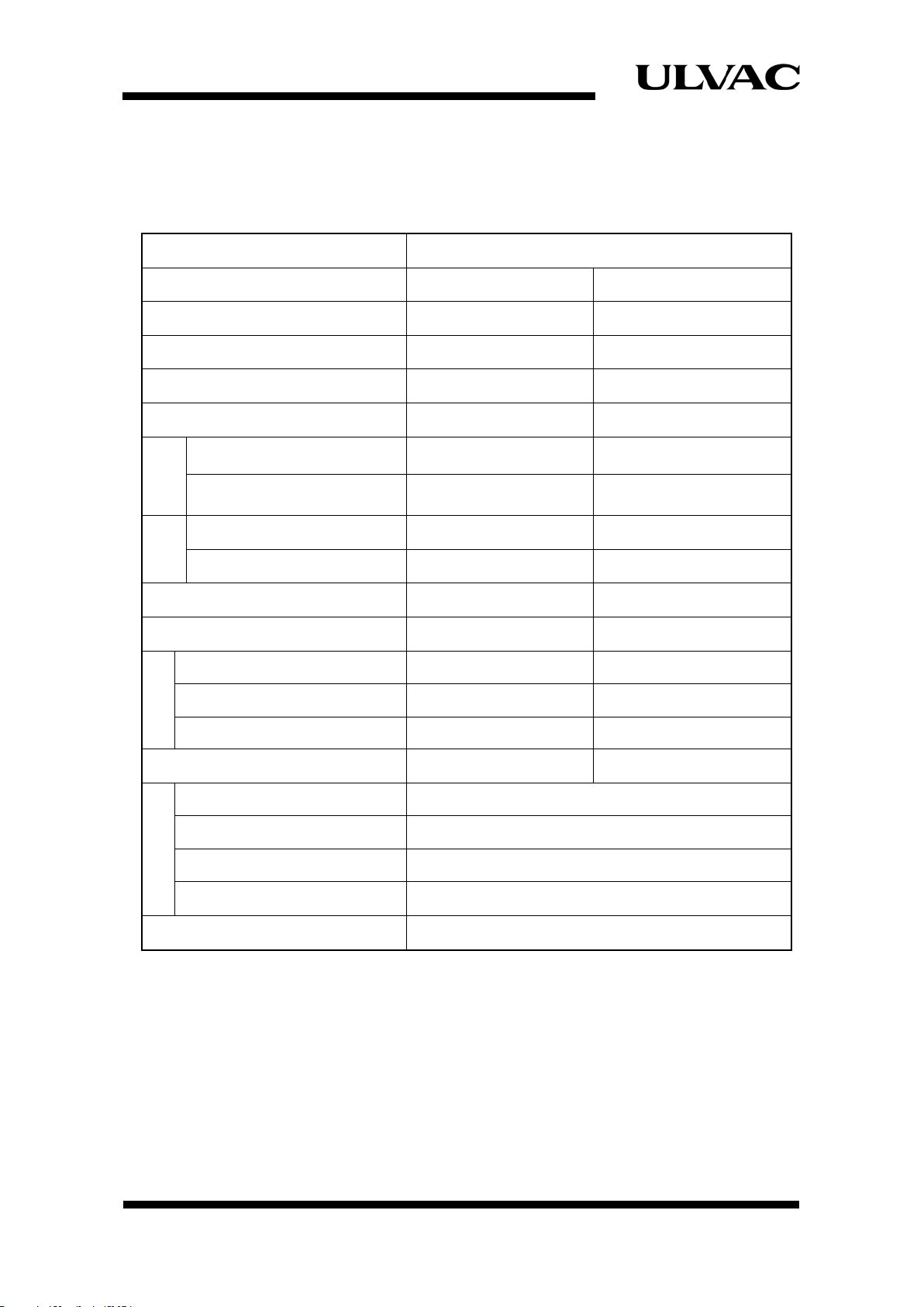
Table 1-1 Compressor Unit SW112-C Specifications............................................... 4
Table 1-2 Control and connection of the compressor unit....................................... 5
Table 1-3 Components and function......................................................................... 8
Table 1-4 List of control components.......................................................................11
Table 1-5 Remote sequence................................................................................... 14
Table 1-6 Remote connectors................................................................................. 14
Table 1-7 Monitor sequence ................................................................................... 14
Table 1-8 Applied connector for remote ................................................................. 14
Table 1-9 Refrigerator connector specifications..................................................... 15
Table 1-10 Connectors for the refrigerator ............................................................... 15
Table 1-11 Safeguards.............................................................................................. 15
Table 2-1 Electric wiring capacity ........................................................................... 19
Table 4-1 Fuse List (Spare fuses are attached to the product).............................. 25

ULVAC CRYOGENICS INCORPORATED 1
Safety Instructions
Ensure to disconnect power before performing installation, maintenance or repair
works. Touching non-isolated parts inside the compressor unit may cause severe
injury including electric shock or equipment damage. Connect the earth wire to Class
C grounding.
This system contains high-pressure helium gas. The gas must be removed before
disassembling for maintenance or disposal. Optional helium charge adopter kit is
required to release helium gas.
Do not use this system in the atmosphere of corrosive gas (such as chlorine). It may
result in damaging human body or equipment failure.
Inside this equipment, there are high temperature areas, such as compressor motor or
discharge line, during operation and immediately after shutdown.
When performing repair or maintenance works, wait until the inside returns to the
normal temperature before start working. If the work starts when it is still hot, there is a
risk of burn injury.
1. Danger of electric shock exists. Do not touch
electric parts.
2. Danger of explosion exists. Do not
expose to corrosive gases.
3. Danger of burn injury exists. Never touch
high temperature surface

2 ULVAC CRYOGENICS INCORPORATED
Disposal Considerations
The equipment and component parts must be disposed in accordance with applicable
local and domestic standards for industrial wastes.
We offer Safety Data Sheet (called SDS) of our products upon your request. For detailed
information please contact our Service Engineering Division or the nearest customer
support center.
WARNING
Do not disassemble, pressurize, heat, and/or throw into fire. The adsorber may
explode.
For safe disposal of an adsorber, follow the procedures below.
1)
Depressurize high pressure helium gas in the adsorber to an ambient
atmospheric pressure. To do so safely, connect the proper tools such as our
charging adaptor (for refrigerator maintenance).
2) Before proceeding with disposal work, remove the couplings of the adsorber to
visually confirm that it has been depressurized.

ULVAC CRYOGENICS INCORPORATED 3
Unpacking and Inspection
Upon receiving the compressor unit SW112-C, immediately check for any damage that
may have occurred during shipping according to the following procedures.
1. Check for any visible dents, etc., on the outside the packaging for shipping. Keep the
packaging for shipping in case you need to make a claim regarding dents, etc.
2. Remove the packaging and check for dents, etc., on the compressor unit.
Never tilt the compressor unit more than 30 degrees.
Tilting the compressor may result in compressor failure or oil leaking into the helium gas
pipes.
Make sure there are no defects in the following (a) - (c).
(a) Overall exterior
(b) Oil leaks
(c) Helium gas charged pressure
Make sure the pressure gauge indicates 2.0 MPa at 20 °C.
If the pressure gauge indicates less than 2.0 MPa, add helium gas according to the
procedures described in 4-1-2 Charging Helium Gas.
If the pressure gauge indicates 0MPa, some impurities may be mixed in the helium gas and
the unit must be replaced.
Please contact us if any problem is observed.
Shipping
When shipping the compressor unit, follow the steps below.
・Attach protection caps to all self-sealing couplings for safe shipping.
・Use the packing materials as same as used at the time of shipment.
・Securely and correctly pack the compressor unit.
・Attach “No Tilting” and “This Side Up” caution labels.

4 ULVAC CRYOGENICS INCORPORATED
1. General Description
1.1 Specifications
Table 1.1 shows the specifications for Compressor Unit SW112-C.
Table 1-1 Compressor Unit SW112-C Specifications
Compressor unit SW112-C
Power source φ, V, Hz Single phase, 100, 50/60
Power consumption *1 kW 1.0/1.2
Starting current *1 A 56/52
Operating current *1 A 11.0/12.2
Compressor nominal output *2 W 700
Ambient
Condition
Installable room temperature ºC 4-38
Installable room humidity %Rah 88 % or lower
Cooling
Water
Flow rate *3 L/min 2 – 5
Inlet temperature *3 °C 5 – 35
Refrigerant Helium gas 99.999 % or purer
Refrigerant filling pressure MPa 2.0±0.05 (20°C)
Size
Height mm 396 (including casters)
Width mm 373
Length mm 449
Weight kg 53
Connection
Cooling water [WATER IN] PS 3/8” female
Cooling water [WATER OUT] PS 3/8” female
Refrigerant [SUPPLY] 1/2”self-sealing coupling
Refrigerant [RETURN] 1/2” self-sealing coupling
Scheduled maintenance intervals Change adsorber every 30,000 hours
Notes 1. Value when connected with a cryopump unit.
2. Motor output when measured with R-22.
3. Refer to “2.2.4 Cooling Water” for detail of cooling water temperature or
flow rates.

ULVAC CRYOGENICS INCORPORATED 5
1.2 Overview / General description
The function of the compressor unit is to supply high-pressure helium gas to the cryogenic
refrigerator and recompress the helium gas returning from the cryogenic refrigerator.
The compressor unit is comprised of the following components- a compressor, cooling system
device, oil separator, absorber, and so on.
1.2.1 Control and connection
Table 1.2 and Figure 1.1 show the control and connection of SW112-C.
Table 1-2 Control and connection of the compressor unit
Item Function
1 RUN Indicator Lamp (GL) Lights when the compressor unit is in operation.
2 TEMP. AL. Indicator Lamp (RL1) Lights when the thermal safeguard of the compressor unit
is in operation.
3 PRESS. AL. Indicator Lamp (RL2) Lights when the pressure safeguard of the compressor unit
is in operation.
4 RUN/STOP Switch (SW1)
・Press to start or stop the compressor unit.
Press the upper half of the switch to start operations. The
RUN indicator lamp will be lit.
Press the lower half of the switch to stop operations. The
RUN indicator lamp will also turn off.
For remote operation, leave this switch ON and use the
remote operation switch.
Use EXTERNAL OPERATION switch supplied on-
site to
turn ON or OFF.
・In the event a blackout occurs during operations, when
the electricity is restored, operations will automatically
resume.
5 HOUR METER (HM) The time counter indicates the total hours of operation of
the compressor unit. There is life to a battery built in HOUR
METER and it is used by about 10 years.
6 He PRESSURE METER
Pressure meter.
When not in operation, indicates the helium gas charge
pressure.
During operation, indicates the compressed helium gas
pressure (supply pressure).
7 He GAS CHARGE Helium gas supply port.
8 SUPPLY Helium gas supply port to the cryogenic refrigerator.
Flexible tube (supply side) is connected.
9 RETURN Return port for helium gas from the cryogenic refrigerator.
Flexible tube (return side) is connected.

6 ULVAC CRYOGENICS INCORPORATED
10 REF. : (CN1) Connection port for the cable connector to supply power to
the refrigerator (motor).
11 REMOTE : (CN2)
Connection port for the cable connector during remote
run/stop of the compressor unit
12 L
Switch
R
To switch between LOCAL operation and REMOTE
operation.
L: start and stop operations with the RUN/STOP switch.
R: When the RUN/STOP
switch is ON, run/stop of
operations is possible using the EXTERNAL OPERATION
switch.
13 POWER SUPPLY CORD Power source cable for 100 V.
14 FUSE Fuse for control circuit protection (250V, 3A).
15 SIGNAL(CN5)
Connection port for the cable connector when the
operation/warning signals are extracted.
16 EARTH Earth terminal for Refrigerator cable.
17 WATER IN Connection port for the cooling water supply line.
18 WATER OUT Connection port for the cooling water return line.

ULVAC CRYOGENICS INCORPORATED 7
Figure 1-1 Compressor Front Panel
5. HOUR METER
12. REMOTE/LOCAL Switch
4. RUN/STOP Switch
6. He PRESSURE METER
7. He GAS CHARGE
18. WATER OUT
17. WATER IN
1. RUN lamp
2. TEMP. AL. Indicator lamp
3. PRESS.AL. Indicator lamp
16. EARTH (pump)
11. REMOTE
15. SIGNAL
10. REF (motor of pump)
14. FUSE
8. SUPPLY
9. RETURN
13. POWER SUPPLY CORD

8 ULVAC CRYOGENICS INCORPORATED
1.2.2 Flow of gas and oil in the compressor unit
Figure 1-2 shows the refrigerant circuit of compressor unit SW112-C.
Table 1-3 and Figure 1-3 show the components inside and the functions of SW112-C.
Table 1-3 Components and function
No Component Function
1 Compressor Compresses helium gas.
2 First heat exchanger Air-cooled heat exchanger for helium compressed gas.
3 Second heat exchanger Air-cooled heat exchanger for helium compressed gas.
4 Oil heat exchanger Air-cooled heat exchanger of lubricating oil.
5 Oil separator Separates oil from compressed helium gas.
6 Absorber
Separates residual oil mist in the processed compressed
helium gas processed by oil separator.
7
Helium gas supply port
(
SUPPLY
)
For connecting flexible tube (helium gas supply port).
8
Helium gas return port
(
RETURN
)
For connecting flexible tube (helium gas return port).
9 Helium gas compensating port Compensating port to compensate helium gas.
10
Pressure adjusting valve for
low pressure
By-pass valve to maintain the pressure of the low-pressure
helium gas above a certain level.
11 Safety valve
Safety pressure valve to maintain the pressure of the
high-pressure at a specified value or below.
12 Solenoid valve(SVC)Solenoid valve for helium gas pipes.
13 Pressure meter
Indicates the helium gas inclusion pressure when not in
operation, and shows the compressed helium gas pressure
during operation.
14
Low-pressure pressure switch
(
63PL
)
Pressure detector to detect a drop in suction gas pressure.
15 Filter Removes dirt and dust from circulating lubricating oil.
16 Capillary tube Adjusts the flow rate of circulating lubricating oil.
17 Thermostat(26G)
Detection and control device for the temperature of the
compressed helium gas at the outlet of the compressor.
18 Control panel
Control monitor and warning system for the helium gas
compressor unit. (See item on “1-
3 Instructions on the
Electrical System.”)
19 WATER IN Connection port for the cooling water supply line.
20 WATER OUT Connection port for the cooling water return line.
Before opening the panel, disconnect all power sources supplied to the compressor unit.
WARNING

ULVAC CRYOGENICS INCORPORATED 9
Figure 1-2 Helium Circuit Diagram

10 ULVAC CRYOGENICS INCORPORATED
Figure 1-3 SW112-C Components inside
16. Capillary tube
11. Safety valve
4. Oil heat exchanger
3. Second heat exchanger
2. First heat exchanger
15. Filter
17. Thermostat
18. Control panel
6
. Adsorber
12
. Solenoid valve
5. Oil separator
1. Compressor
10. Pressure adjusting valve
for low-pressure

ULVAC CRYOGENICS INCORPORATED 11
1.3 Instructions for the Electrical System
1.3.1 Control Components
The control components for SW112-C are shown in Table 1-4 and Figure 1-4.
Table 1-4 List of control components
No. Name of component Code Component number Specifications
Vol
um
e
1
RUN indicator lamp
GL
BN3802-1G
AC100 V GREEN
1
2
TEMP.AL. indicator lamp
RL
BN3802-1R
AC100 V RED
1
3
PRESS.AL. indicator lamp
RL
BN3802-1R
AC100 V RED
1
4
RUN/STOP switch
SW1
AJ911102B3F
AC250 V 16A
1
5
REMOTE/LOCAL switch
SW2
S-1-Z
AC250 V 4A
1
6
Operation hour meter
HM
H7ET-N-300
DC3 V (internal
battery)
1
7
Refrigerator connector
CN1
N/MS3102A14S-2S
4P
1
8
Remote connector
CN2
N/MS3102A14-7S
3P
1
9
Connector
CN3
VLR-04V-R
AC600 V 20A 4P red
1
10
Connector
CN4
VLP-04V
AC600 V 20A 4P
white
1
11
Fuse
Fuse holder F1,F2,
HT3.15AN5
F-400-01-A2
AC250 V 3.15A
AC250 V 10A
2
2
12
Overload protector
(inside the compressor)OLR MRA98283-9200 20.0 A at 80 °C 1
13
Temperature limiter
26G
CS-74L120
120 °C
1
14
Pressure switch
63PL
ACB-1AU3
OFF: 0.098 MPa
1
15
Relay
52CM
G7L-2A-BUB
AC100 V
1
16
Delay relay
Socket (with holding clamp)
2T1,2
ST7P-2
TP814X1
AC100 V
Setup: 1 second
2
2
17
Auxiliary relay
Socket (with holding clamp)
4X1
HH54P
TP514X1
AC100 V
1
1
18
Auxiliary relay
Socket (with holding clamp)
4XOP,2,
3
HH52P
TP58X2
AC100 V
3
3
19
Starting relay
19C
AMVL-180A
1
20
Power source terminal
TB1
AYBN023-1
600 V 25A 3P
1
21
Terminal for control
TB2
KTUNS-10J
600 V 10A 10P
1
22
Power cord terminal
TB3
AYBN023-1
600 V 25A 3P
1
23
Solenoid valve coil
SVC
NEV-M0AC571UB0
AC100 V
1
24
Running capacitor
C1
RS22B606U4364A
220 V 60 μF
1
25
Starting capacitor
C2
DMS-1FJ150R
160 V 150 μF
1
26
Signal connector
CN5
DE-9P-NR
9P
1
Before opening the panel, disconnect all power sources supplied to the compressor unit.
WARNING

12 ULVAC CRYOGENICS INCORPORATED
Figure 1-4 SW112-C Control Components (Exterior components)
9. REMOTE
2
6. SIGNAL
7
. REF (refrigerator motor)
11. FUSE
3. PRESS.AL. indicator lamp
2. TEMP. AL. indicator lamp
1. RUN indicator lamp
6. HOUR METER
5. REMOTE / LOCAL switch
4. RUN / STOP switch

ULVAC CRYOGENICS INCORPORATED 13
Figure 1-5 SW112-C Control Components (Inside)
2
3. Solenoid valve coil
1
2. Overload relay
2
4. Running capacitor
9
. Connector
1
0. Connector
1
3. Temperature limiter
2
1. Terminal for control
2
0. Power source terminal
2
2. Power source terminal
2
5. Starting capacitor
1
5. Relay
19
. Starting relay
1
6. Delayed relay
8
. Remote connector
2
6. Signal connector
7. Refrigerator connector
11. Fuse
18.
Auxiliary relay
14
.Pressure switch
17
. Auxiliary relay

14 ULVAC CRYOGENICS INCORPORATED
1.3.2 Remote Connector
The remote connector can be used to remotely operate of the compressor unit.
Table 1.5 shows the remote operation sequence.
Table 1-5 Remote sequence
No.
Item
Condition
Pin code
Contact point capacity
1 Remote
operation
Suspended
Released
A, B
Rated capacity:
100VAC 0.1A or more
Minimum load:
100VAC 0.01A
In Operation Connected
Table 1-6 Remote connectors
Name
Specifications
Plug connectors
(Straight type)
Made by Japan Aviation Electronics Industry, Ltd.
N/MS3106B-14S-7P
Plug connectors
(Angle type)
Made by Japan Aviation Electronics Industry, Ltd.
N/MS3108B-14S-7P
Cable clamps
Made by Japan Aviation Electronics Industry, Ltd. N/MS3057-6A
Figure 1-6 Remote connector pin locations
1.3.3 Signal Connector
The signal connector can be used to monitor conditions.
Table 1.7 shows the monitor sequence of the compressor unit.
Table 1-7 Monitor sequence
No. Items Condition Pin code Contact point capacity
1 Operation monitor
No-voltage
contact
Running Close
Suspended Open
1 , 2 24VDC 0.1A
2
TEMP.
Warning monitor No-voltage
contact
Normal Open
Warning Close 4 , 5 24VDC 0.1A
3
PRESS.
Warning monitor No-voltage
contact
Normal Open
Warning Close 3 , 5 24VDC 0.1A
Table 1-8 Connectors for signals
Name
Specifications
Plug connectors
Japan Aviation Electronics Industry, Ltd. DE9S-NR
Figure 1-7 Signal connector pin configuration
C
B
A
This is the socket side insert, as seen from the pins at
front of connector.
8
1 52
97
3
6
4
Socket side insert viewed from the pins at
front of connector.
Table of contents
Other Ulvac Air Compressor manuals
Popular Air Compressor manuals by other brands

Paramina
Paramina MISTRAL CLASSIC M6-ET user manual

Dorin innovation
Dorin innovation 2Q-80VS Series Operating instruction

Vilter
Vilter 320 operating manual

BOCK
BOCK HGX12 CO2 T Series Assembly instructions

Clarke
Clarke SSC1000G Operation & maintenance instructions

Hitachi
Hitachi NEXT Series instruction manual