IMPORTANT
INFORMATION
Safety First: This
equipment
must
be
operated
and
maintained
with
the
safety
of
the
patient
and
doctor
in
mind.
1. Read
this
manual
before
operating
your
new
UMF
Medical
equipment.
2. This
product
is
intended
to
be
used
for positioning
of
patients
during
medical
examinations
conducted
by qualified
medical
personnel.
3. This
manual
should
remain
permanently
affixed
or
near
the
equipment
for
convenient
reference.
4.
UMF
Medical reserves
the
right
to
make
changes
to
the
design
of
products
at
anytime
and
without
notice.
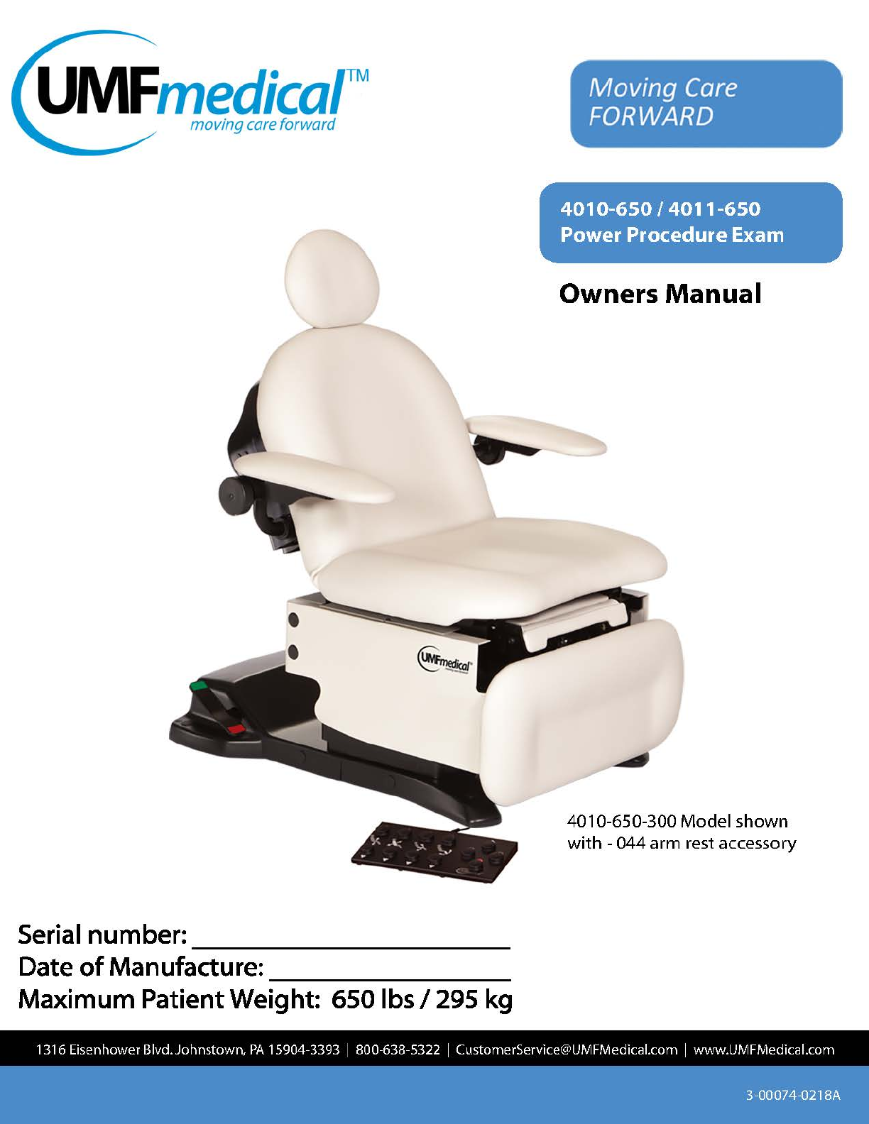
INTENDED
USE
This
table
is
intended
for
patients
weighing
no
more
than
650
lbs
/295
kg
distributed
evenly
over
the
entire
table
surface.
Patient
should
be
evenly
supported
over
the
entire
table
length.
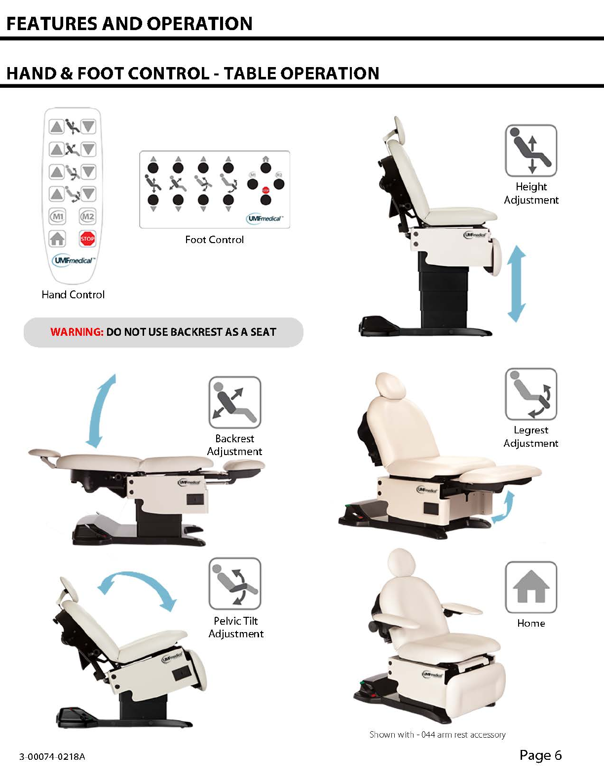
Back
rest
is
not
intended
to
be
used
as
a
seat
or
to
support
entire
patient
weight.
Use
of
the
back
rest
as
a
seat
or
to
support
entire
patient
weight
is
considered
misuse
and
may
cause
back
to
fail
causing
potential
injury.
CLASSIFICATIONS
Equipment
Class -Class I
Protection
against
electric shock:
Type
B
applied
parts
Protection
against
harmful
ingress
of
water:
Ordinary
Equipment
is
not
suitable
for
use
in
the
presence
of
a
flammable
anesthetics
mixture
with
air
or
with
oxygen
or
with
nitrous
oxide
Mode
of
Operation:
Continuous
operation
with
intermittent
loading
1
minute
on
9
minutes
off
or
2
minutes
on,
18
minutes
off.
This
product
has
been
evaluated
with
respect
to
electrical shock,fire & mechanical
hazards
only, in
accordance
with
UL60601-1
and
CAN/CSA-22.2 No. 601.1
SAFETY SYMBOLS
lJMFmedi
car M
ed
ical Equi
pmen
t
~''.
...
c@
us
29ZE
Mode
l:
4010
5/N:
114017
-0001
Bullt:
Feb
22,
2013
~
*
120
VOLT
60
HZ
9
AMP
(255428
UL6060l•l,
CANJCSA•22.2 NO.
601
.
l•M90
MAX
I
MUM
WEIGHT CAPACITY: 650l8S/29SKG
JOH
NSTOWN
,
PA·
MADE
IN
THE
USA
111111111111111
II
IIII
I
II
I
II
IllI
Ill
IllIIIIll
114017-0001
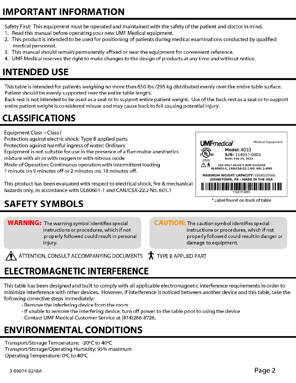
* Label
found
on back
of
table
WARNING: The warning symbol identifiesspecial
instructions or procedures,which
if
not
properlyfollowed could result in personal
injury.
CAUTIO The cautionsymbol identifies special
instructions or procedures, which if
not
properlyfollowed could result
in
danger or
damage
to
equipment.
~
ATTENTION,
CONSULT
ACCOMPANYING
DOCUMENTS
t
TYPE
B
APPLIED
PART
ELECTROMAGNETIC
INTERFERENCE
This
table
has
been
designed
and
built
to
comply
with
all
applicable
electromagnetic
interference
requirements
in
order
to
minimize
interference
with
other
devices. However, if
interference
is
noticed
between
another
device
and
this
table,
take
the
following corrective
steps
immediately:
-Remove
the
inferfering
device
from
the
room
-
If
unable
to
remove
the
interfering device,
turn
off
power
to
the
table
prior
to
using
the
device
-
Contact
UMF
Medical
Customer
Service
at
(814)266-8726.
ENVIRONMENTAL
CONDITIONS
Transport/Storage
Temperature:
-20°C
to
40°C
Transport/Storage/Operating
Humidity: 95%
maximum
Operating
Temperature:
0°C
to
40°C
3-00074-021BA
Page2