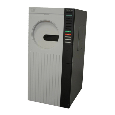
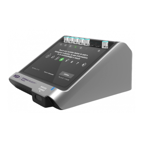
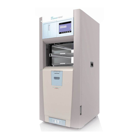
ASP sterrad NX User manual

STERRAD®NX™
Sterilization
System
Service Troubleshooting
Guide

STERRAD®NX™Sterilization System
Service Troubleshooting
Guide
1-888-STERRAD (1-888-783-7723)
ASP USA Customer Care Center
www.sterrad.com
International Technical Support 001.949.581.5799
ASP International Customer Support
(Call your local ASP Customer Support Representative)
© 2005. Advanced Sterilization Products. All rights reserved. Other products mentioned in this publication
are trademarked by their respective owners. Reproduction, adaptation, or translation of this publication
without prior written permission is prohibited. Printed in the U.S.A.
08-53528-0-001 TS-53527-0-001 Rev A
2 STERRAD®NX™Service Guide

Contents
Chapter 1. Introduction 7
Overview ...........................................................................................................................................7
Sterilant and Cassette.........................................................................................................................8
Hardware ...........................................................................................................................................8
Software.............................................................................................................................................8
Chapter 2. Safety Information 11
Personal Safety and First Aid ............................................................................................................11
Cassette Handling ........................................................................................................................13
Personal Protection Equipment..........................................................................................................13
Warnings, Cautions, and Notes..........................................................................................................14
Symbols Used on the Sterilizer and in This Guide ............................................................................14
Safety Standards Compliance ............................................................................................................15
Chapter 3. Functional Description 17
Overview of the Sterilization Process................................................................................................17
Hydrogen Peroxide Concentration and Delivery ...............................................................................18
Process Monitoring and Control........................................................................................................18
Temperature .................................................................................................................................19
Pressure........................................................................................................................................19
Hydrogen Peroxide Monitor ........................................................................................................19
Plasma Power...............................................................................................................................20
Time .............................................................................................................................................20
System Software ................................................................................................................................20
Functional Block Diagram.................................................................................................................22
Subsystems ........................................................................................................................................23
Hydrogen Peroxide Delivery Subsystem .....................................................................................23
Vaporization Subsystem ..............................................................................................................23
Vacuum Subsystem......................................................................................................................23
Plasma Subsystem........................................................................................................................23
Hydrogen Peroxide Monitor Subsystem ......................................................................................23
Modular Design .................................................................................................................................24
Modules and Subsystem Details ..................................................................................................25
Top Module .......................................................................................................................................27
Chassis .........................................................................................................................................27
Access Panels...............................................................................................................................28
Display Assembly ........................................................................................................................28
Cassette Drawer ...........................................................................................................................28
Delivery System...........................................................................................................................28
Vaporizer/Condenser ...................................................................................................................28
Power Inlet Connector .................................................................................................................28
AC Distribution............................................................................................................................29
DC Power Supply ........................................................................................................................29
System Controller ........................................................................................................................29
Fan ...............................................................................................................................................29
Chamber Module ...............................................................................................................................30
Access Panels...............................................................................................................................30
Door Assembly ............................................................................................................................30
Chamber and Shelves...................................................................................................................31
Electrode ......................................................................................................................................31
STERRAD®NX™Service Guide 3

Feedthrough................................................................................................................................. 31
Base Module ..................................................................................................................................... 32
Frame and Chassis....................................................................................................................... 33
Access Panel................................................................................................................................ 33
Circuit Breaker ............................................................................................................................ 33
LFPS II Power Supply................................................................................................................. 33
Printer.......................................................................................................................................... 33
Vacuum Pump Assembly ............................................................................................................33
Diagnostic Functions and Tests ........................................................................................................ 34
Subsystems and Components ...................................................................................................... 34
Door Heater Resistance Configuration........................................................................................ 36
Process Variables and Cancellation Limits.......................................................................................37
Chapter 4. Diagnostic Tests and Error Messages 39
Diagnostic Files ................................................................................................................................ 39
Diagnostics........................................................................................................................................ 39
Diagnostic Tests .......................................................................................................................... 40
Troubleshooting ................................................................................................................................ 42
Error Messages............................................................................................................................ 42
Diagnostic Messages ................................................................................................................... 47
Chapter 5. Subassembly Removal and Replacement 53
Access to Sterilizer Interior............................................................................................................... 53
Front Top Panel (02-51326) ........................................................................................................ 54
Top Panel (33-51196).................................................................................................................. 55
Rear Top Panel (33-51197) ......................................................................................................... 56
Front Bottom Panel (33-51195) .................................................................................................. 57
Right Side Panel (33-51193) ....................................................................................................... 58
Left Side Panel (33-51193) ......................................................................................................... 59
Door Cover (33-51993)............................................................................................................... 60
Top Module....................................................................................................................................... 61
Delivery System Assembly (02-51984) ...................................................................................... 61
Delivery Valve ............................................................................................................................ 63
Delivery Subsystem Inlet Filter (PM kit part 25-50703)............................................................ 63
Air Pump Tubes .......................................................................................................................... 63
Vaporizer/Condenser Assembly (02-52410) ............................................................................... 64
Vent Valve (28-51218)................................................................................................................ 66
Chamber Pressure Control Assembly (02-52387)....................................................................... 68
Circuit Boards Assembly: Universal Control Board (UCB) (04-50361) and Interface Board (04-
52006) ......................................................................................................................................... 70
Alternating Current (AC) Distribution Assembly (02-51959) .................................................... 72
Direct Current (DC) Power Supply (40-51141) .......................................................................... 74
Display Assembly (40-50532).....................................................................................................76
Fan Assembly (04-51991) ........................................................................................................... 78
Door Lock Solenoid (42-52001) and Door Lock Sensor (04-51990)......................................... 79
Power Inlet Connector (45-51407).............................................................................................. 80
Ultraviolet Lamp Power Supply (40-51449) ............................................................................... 81
Hydrogen Peroxide Monitor Lamp Assembly (04-50544).......................................................... 82
Chamber Module .............................................................................................................................. 84
Electrode Assembly (03-51157) Spacers and Slides (35-51152), Lower Shelf Stop (35-51153),
Upper Shelf Stop (33-51158) ...................................................................................................... 84
Door Assembly (03-51985)......................................................................................................... 85
Door Seal O-Ring (22-00537).....................................................................................................87
Latch Assembly (74-51398)........................................................................................................ 88
4 STERRAD®NX™Service Guide

..............................................................................................................
Hydrogen Peroxide Detector Assembly (04-52108) ....................................................................89
Base Module ......................................................................................................................................90
Vacuum Pump Assembly (04-52158)..........................................................................................90
Catalytic Converter (25-05611) ...................................................................................................92
Oil Mist Filter (25-51970)............................................................................................................93
Vacuum Control Valve (28-51216) .............................................................................................94
Oil Return Valve (28-51971) .......................................................................................................95
Low Frequency Plasma System (LFPS II) (40-52154) ................................................................96
Printer Assembly (04-51482).......................................................................................................97
Circuit Breaker (57-52105)..........................................................................................................99
Chapter 6. Planned Maintenance 101
Overview ...........................................................................................................................................101
Vacuum Pump Oil Replacement........................................................................................................102
Catalytic Converter Replacement ......................................................................................................103
Oil Mist Filter Replacement ..............................................................................................................103
Air Filter Replacement.......................................................................................................................103
Vent Valve HEPA Filter Replacement ..............................................................................................103
Hydrogen Peroxide Detector Lamp ...................................................................................................104
Delivery Subsystem Inlet Filter Replacement ...................................................................................105
Air Pump Tubes Replacement ...........................................................................................................105
Door Seal O-Ring Replacement ........................................................................................................106
Chamber/Electrode/Plastics ...............................................................................................................107
Thermistor Replacement....................................................................................................................107
Chamber Thermistor Replacement...............................................................................................107
Door Thermistor Replacement.....................................................................................................108
Condenser/Vaporizer Thermistors Replacement..........................................................................109
Cassette Disposal and Printer Maintenance.......................................................................................109
Replacing a Cassette Disposal Box..............................................................................................110
Inserting a New Cassette Disposal Box .......................................................................................110
Cleaning the Thermal Printer Head..............................................................................................111
Replacing the Printer Paper..........................................................................................................112
STERRAD®NX™Service Guide 5

Chapter 7. System Calibration and Verification 115
Overview........................................................................................................................................... 115
Service Action Table......................................................................................................................... 115
Zeroing Pressure Transducers........................................................................................................... 116
Leak Test........................................................................................................................................... 117
Plasma Power Delivery Verification................................................................................................. 118
Temperature Calibration Using A Temperature Bath or Precision Resistors.................................... 119
Peroxide Calibration With Neutral Density Filters ........................................................................... 122
Diagnostics.................................................................................................................................. 123
Temperature Verification.................................................................................................................. 123
Appendix A. STERRAD®NX™Sterilizer Specifications 125
6 STERRAD®NX™Service Guide

Introduction 1
Chapter 1.
Introduction
Overview
The STERRAD®NX™Sterilizer is a self-contained stand-alone system
of hardware and software designed to sterilize medical instruments and
devices using a patented hydrogen peroxide gas plasma process.
Hydrogen peroxide vapor is generated by delivering aqueous hydrogen
peroxide into the vaporizer where the solution is heated and vaporized.
The hydrogen peroxide vapor is then introduced into the sterilization
chamber, under sub-ambient pressure, where it is transformed into a gas-
plasma by use of electrical energy.
The STERRAD NX Sterilizer is designed for low temperature
sterilization of both metal and nonmetal medical devices. Because the
cycle operates within a dry environment and at low temperatures, it is
especially suitable for instruments sensitive to heat and moisture.
The STERRAD NX Sterilizer employs a modified method of delivering
hydrogen peroxide to sterilize devices within the sterilization chamber.
This modified process concentrates the 59% hydrogen peroxide to 90%
nominal hydrogen peroxide (by selectively vaporizing and removing
water) prior to being transferred into the sterilization chamber.
In addition, by using the concentrated hydrogen peroxide solution, the
sterilization cycle times have been reduced.
STERRAD®NX™Service Guide 7

1 Introduction
Sterilant and Cassette
The sterilant used in the STERRAD NX Sterilizer is hydrogen peroxide.
It is supplied in cassette form as a separate accessory.
The cassette shell is made of white, high impact polystyrene. Each
cassette encapsulates 10 individually sealed cells. Each of the filled cells
of the cassette contains 1800 µl (±50 µl) of 59% nominal hydrogen
peroxide. Each sterilization cycle uses two cells; therefore, a cassette can
process five sterilization cycles.
Hardware
The hardware for the sterilizer consists of a sterilization chamber and a
variety of instruments and components which are housed in a covered
frame. The sterilizer system also uses accessories such as a disposable
sterilant cassette, reusable instrument trays, printer paper, and an optional
movable cart. The STERRAD NX Sterilizer can be placed directly on a
table, counter top, or on the movable cart.
Software
The sterilization process is controlled automatically by software. The
software controls and monitors the hardware through digital and analog
signals. Functions managed by software include:
♦ Time
♦ Temperature/pressure measurement and control.
♦ Sterilant delivery and vaporization.
♦ Plasma power generation and measurement.
♦ Hydrogen peroxide monitor
♦ Access to chamber through lock-controlled door.
8 STERRAD®NX™Service Guide

Introduction 1
Each parameter is part of a control loop in which information flows as
input from one of many sensors to the computer, where it is processed
and triggers an output signal which flows from the computer to an output
device. Through this system of feedback signals (input), analysis, and
response signals (output), the computer controls the entire sterilization
process. If any process parameter falls outside allowable ranges, the
software will cancel the cycle.
4Note: The hydrogen peroxide monitor does not provide
feedback control to the sterilizer. However, the
monitor will cancel the cycle if the area under the
hydrogen peroxide concentration-time curve or
hydrogen peroxide rate constant does not meet
specifications.
STERRAD®NX™Service Guide 9


Safety Information 2
Chapter 2.
Safety Information
Your safety is of primary concern to Advanced Sterilization Products.
This chapter provides information on safely servicing the STERRAD®
NX Sterilizer. You must read and understand the safety information
in this chapter before performing service on the sterilizer. Always
pay attention to the warnings, cautions and notes throughout this Service
Guide.
Personal Safety and First Aid
WARNING! HYDROGEN PEROXIDE IS CORROSIVE.
Concentrated hydrogen peroxide is corrosive to skin, eyes, nose, throat, lungs,
and the gastrointestinal tract. Always wear latex, PVC (vinyl), or nitrile gloves
while removing items from the sterilizer following a cancelled cycle. Following a
cancelled cycle, if items in the load show any visible moisture or liquid,
hydrogen peroxide may be present.
WARNING! HYDROGEN PEROXIDE IS AN OXIDIZER.
Avoid allowing hydrogen peroxide to contact organic materials, including paper,
cotton, wood, or lubricants. Concentrated hydrogen peroxide is a strong oxidizer
and may react with organic materials, causing ignition and fire.
WARNING! RISK OF EYE INJURY.
Direct hydrogen peroxide contact with eyes can cause irreversible tissue damage.
If contact with eyes occurs, immediately flush with large amounts
of water. Consult a physician immediately.
WARNING! RISK OF SKIN INJURY.
Direct hydrogen peroxide contact with the skin can cause severe irritation.
If skin contact occurs, immediately flush with large amounts of water.
If symptoms are severe or persist, consult a physician immediately.
WARNING! RISK OF RESPIRATORY IRRITATION.
Inhalation of hydrogen peroxide mist can cause severe irritation of lungs, throat,
and nose. If inhalation occurs, move to fresh air. Consult a physician
immediately.
STERRAD®NX™Service Guide 11

2 Safety Information
WARNING! CONCENTRATED HYDROGEN PEROXIDE IS TOXIC.
Ingestion of hydrogen peroxide may be life-threatening. If swallowed, drink
plenty of water immediately to dilute. Do not induce vomiting. Consult a
physician immediately.
WARNING! HOT SURFACES.
Components in the interior of the sterilizer may be hot. Do not touch the inside of
the chamber or door with your bare or gloved hands when the sterilizer is
operating. Allow the sterilizer to cool before touching interior surfaces.
CAUTION: AVOID EXPOSURE TO ULTRAVIOLET LIGHT.
The hydrogen peroxide monitor uses an ultraviolet light source located inside the
chamber behind the door. To avoid eye injury, do not stare directly at the
ultraviolet light source for an extended period of time. Use protective eyewear if
necessary.
WARNING! ELECTRIC SHOCK HAZARD.
High voltages are present inside the sterilizer. Contact with electrically energized
parts can cause injury or death. Turn OFF and unplug the sterilizer before
performing service tasks.
12 STERRAD®NX™Service Guide

Safety Information 2
Cassette Handling
STERRAD CASSETTES CONTAIN CONCENTRATED HYDROGEN
PEROXIDE, A STRONG OXIDIZER. CONCENTRATED
HYDROGEN PEROXIDE IS CORROSIVE TO SKIN, EYES, NOSE,
THROAT, LUNGS, AND GASTROINTESTINAL TRACT. Direct
contact with the skin can cause severe irritation. If skin contact occurs,
immediately flush with large amounts of water. If symptoms are severe or
persist, consult a physician immediately. Direct contact with eyes can cause
irreversible tissue damage. If eye contact occurs, immediately flush with
large amounts of water and immediately consult a physician. Inhalation of
vapor or mist can cause severe irritation of lungs, throat, and nose. If
inhalation occurs, move to fresh air and consult a physician immediately.
Ingestion can produce corrosion that may be life threatening. If swallowed,
immediately drink plenty of water to dilute. Do not induce vomiting. Consult
a physician.
Do not remove the plastic wrapper from the cassette package if the indicator
strip is red. Red indicates that the cassette might have been damaged. Call
your ASP representative for credit.
Do not remove used cassettes from the cassette collection box. Dispose of
the sealed cassette collection box according to local waste regulations.
Cassettes with unused hydrogen peroxide are hazardous waste as defined by
the Environmental Protection Agency (USA) and should be disposed of
accordingly. If it is necessary to handle a used cassette, wear latex, PVC
(vinyl), or nitrile gloves. Do not touch gloves to face or eyes.
Empty or expired cassettes must be replaced prior to starting the cycle as
directed by a message on the sterilizer display. Cassettes with unused
hydrogen peroxide are hazardous waste as defined by the Environmental
Protection Agency (USA) and should be disposed of accordingly.
Personal Protection Equipment
Wear latex, PVC (vinyl), or nitrile gloves whenever handling a load after a cycle
cancellation. Hydrogen peroxide liquid may be present on the load or in the
chamber.
STERRAD®NX™Service Guide 13

2 Safety Information
Warnings, Cautions, and Notes
ÌWarnings and cautions are accompanied by symbols surrounded by a triangle and
are printed in the text in bold. Warnings indicate events or conditions that can result
in serious injury or death. Cautions indicate events or conditions that can result in
severe damage to the equipment.
4 Notes are printed in italics and have a checkmark in front of the word “Note.” Notes
highlight specific information about the proper use and maintenance of the
STERRAD®NX™Sterilization System.
Symbols Used on the Sterilizer and
in This Guide
Hot surfaces present.
Do not touch without protection.
Hazardous chemical present.
Use personal protective equipment.
Toxic chemical present.
Avoid exposure, contact, or ingestion.
Ultraviolet (UV) light hazard.
Do not look at the light without UV eye protection.
High voltage hazard.
I/O On/Off.
Alternating current.
14 STERRAD®NX™Service Guide
Safety Information 2
Safety Standards Compliance
The STERRAD®NX™Sterilizer meets the following safety standards:
♦ CAN/CSA-C22.2 No. 1010.1B: 1997; Safety Requirements for
Electrical Equipment for Measurement, Control, and Laboratory
Use.
♦ UL 61010A-1: 2002; Standard for Safety for Electrical Equipment
for Laboratory Use.
♦ EN 61010-1: 2001; Safety Requirements for Electrical Equipment
for Measurement, Control, and Laboratory Use.
♦ EN 61010-1-2: 2001; Medical Electrical Equipment, Part 1: General
Requirements for Safety, Section 2: Collateral Standard:
Electromagnetic Compatibility.
♦ IEC 60601-1-2; Medical Electrical Equipment. Part 1-2 General
Requirements For Safety. Collateral standard: Electromagnetic
Compatibility.
STERRAD®NX™Service Guide 15

Functional Description 3
Chapter 3.
Functional Description
Overview of the Sterilization
Process
The STERRAD®NX™ Sterilizer software interfaces with the hardware
through digital/analog input and output signals and through serial
communications via serial ports. The inputs monitor the sterilization
process while the outputs control the process. The process occurs as
follows:
1. The items to be sterilized are placed in the sterilization chamber, the
chamber door is closed, and a vacuum pump reduces the pressure in
the chamber.
2. A 59% aqueous solution of hydrogen peroxide is injected into the
delivery system condenser where it is condensed and concentrated
and then introduced into the chamber.
3. A low frequency electric current is delivered to the chamber
electrode, causing the formation of a low temperature gas plasma in
the chamber.
4. In the plasma state, the hydrogen peroxide vapor breaks apart into
reactive molecules that include free radicals.
5. The combined use of hydrogen peroxide and plasma safely and
rapidly sterilizes most medical instruments and materials without
leaving toxic residues.
STERRAD®NX™Service Guide 17

3 Functional Description
Hydrogen Peroxide Concentration
and Delivery
During the hydrogen peroxide delivery step, hydrogen peroxide solution
is delivered into the vaporizer bowl at atmospheric pressure conditions.
Air is removed from the chamber and from the vaporizer/condenser by
pulling a vacuum to a controlled pressure in the vaporizer/condenser. At
this time, the transfer valve is closed. Water is removed from the 59%
hydrogen peroxide solution by reducing the pressure in the condenser.
The pressure differential between the chamber and the condenser creates
the driving force to remove the water. During this concentration step, the
flow of water vapor is restricted by an orifice between the condenser and
the chamber, creating lower chamber pressure.
Once the controlled pressure is achieved in the condenser, the chamber
pressure is further reduced by closing the orifice with the transition
valve. The condenser temperature is increased and the concentrated
hydrogen peroxide vapor is then transferred into the chamber by opening
the transfer valve and the transition valve. This transfer step is followed
by the diffusion step (which occurs at atmospheric pressure), followed by
pressure reduction and plasma. The vent step then occurs which returns
the chamber to atmospheric pressure. This process occurs twice during a
complete sterilization cycle.
Process Monitoring and Control
The monitoring and control systems regulate the following:
♦ Temperature
♦ Pressure
♦ Hydrogen peroxide monitor
♦ Plasma power
♦ Time
♦ Process status
♦ IMS
18 STERRAD®NX™Service Guide
Functional Description 3
Temperature
Temperature monitoring and control are involved in two aspects of the
STERRAD NX Process: heating and cooling of the condenser that
condenses hydrogen peroxide during vaporization, and heating the
vaporizer, chamber walls and door. The temperature control loop
consists of heaters and temperature sensors. There are five temperature
sensors in the system. The are located on the vaporizer, condenser, door,
chamber front, and chamber rear.
Pressure
Pressure monitoring and control are performed by a control loop which
includes the vacuum pump, vacuum control valve, vent valve, three
pressure transducers and an atmospheric pressure switch. The control
system interacts with these components during chamber evacuation,
pressure monitoring, and venting to atmosphere. Two chamber pressure
transducers monitor and control the vacuum process; one ranges from 0-
30 torr and the other ranges from 0-200 torr. The pressure transducers are
attached to a port in the top of the chamber. The vaporizer pressure
transducer monitors and controls the vacuum during the vaporization
pumpdown step; its range is from 0-30 torr. The pressure transducer is
attached to a port in the vaporizer/condenser assembly. The atmospheric
pressure switch is a differential pressure sensor. Its function is to signal
the control system that the interior of the chamber is at or very near
atmospheric pressure.
Hydrogen Peroxide Monitor
During the hydrogen peroxide transfer step, hydrogen peroxide
concentration data are collected from the monitor. The ultraviolet lamp
assembly sits at the top front of the chamber and delivers UV light across
the chamber to the detector mounted at the bottom of the chamber.
Hydrogen peroxide vapor absorbs UV light – reducing the intensity of
light reaching the detector by an amount proportional to the amount of
hydrogen peroxide present in the light path. A photodiode detector
measures the amount of light coming from the lamp, before and during
hydrogen peroxide transfer to the chamber, allowing a calculation of the
hydrogen peroxide concentration. The area under the concentration-time
curve and the hydrogen peroxide rate constant are calculated and
compared to specifications, by the controller. If the limits are exceeded,
the cycle is cancelled.
STERRAD®NX™Service Guide 19

3 Functional Description
Plasma Power
The plasma power monitoring and control system controls the plasma
power during the two plasma steps of the STERRAD NX Sterilizer
process. The plasma power is monitored and controlled by a plasma
power sensor. This sensor interacts in a control loop with the computer
and plasma power unit to control the process within the specified limits.
Time
Time monitoring and control are performed by the computer and affect
numerous steps in the process. An interval timer measures process step
duration and the computer uses time inputs to control the various devices
in the process sequence.
System Software
STERRAD NX Sterilizer software controls and monitors the sterilizer
through digital and analog signals. When a sterilization cycle is not in
process, the software monitors and controls the sterilizer temperature,
responds to operator touch panel inputs (Select Cycle and Start Cycle),
verifies cassettes upon insertion, controls printer output, and allows the
operator to set the system date and time. When a sterilization cycle is in
process, the software controls and monitors the timing, temperature,
pressure, delivery and vaporization processes, application of plasma
power, printer output, and responds to an operator input of CANCEL (all
other operator inputs are disabled during the cycle). If sterilization
process parameters fall outside allowable ranges, the software will cause
the cycle to cancel, and will control the cancellation process.
Each sterilizer subsystem is part of a control loop in which information
flows as input from one or more sensors to the computer, where it is
processed and triggers an output signal which flows from the computer
to an output device. Through this system of feedback signals (input),
analysis, and response signals (output), the computer controls the entire
sterilization process.
20 STERRAD®NX™Service Guide
Other manuals for sterrad NX
1
Table of contents
Other ASP Laboratory Equipment manuals
Popular Laboratory Equipment manuals by other brands

Sartorius Stedim Biotech
Sartorius Stedim Biotech Flexel Series user manual

Bullard
Bullard Powerhouse installation manual

Tuttnauer
Tuttnauer Valueklave 2540 Technician manual

JENCONS
JENCONS Safetypette Pro Operator instructions

cavitation
cavitation RF SUPER user manual

Kendro
Kendro HERAsafe KS operating instructions