Underground Magnetics Mag 3 User manual

Operator’s Manual
www.undergroundmagnetics.com


1: Introduction………………………………………...…….1
2: Caution………………………….…………………...……2
3: System Highlights…………………………………...….3
4: Receiver……………………………….………………….4
4.1: Specifications…………………………….....…...4
4.2: Receiver Operation………………………..….…4
4.3: Icons………………………………………………5
4.3.1: Main Page Icons……………..…………5
4.3.2: Secondary Page Icons…………………6
4.3.3: Calibrations and
Depth Forecast Page Icons……………7
4.3.4: Setup Page Icons……………………….7
4.4: Calibration……………………………………...…8
4.4.1: Depth Calibration…………………...…..8
4.4.2: Roll Calibration…………………….……9
4.5: Operation…………………………………..……10
4.5.1: Depth Forecast…………………...……10
4.5.2: Transmitter Activation…………………11
4.5.3: Transmitter Settings……………..……12
4.5.4: Receiver Settings………………...……13
4.5.5: Radio Channel Selection………..……14
4.5.6: Radio Registration……………….……15
4.5.7: Pitch Unit Selection…………….……..16
4.5.8: Depth Unit Selection…………………..17
4.5.9: Time Setting……………………………18
4.5.10: System Unlock…………………….….19
4.5.11: Visibility Control………………………20
4.6: Receiver Maintenance…………………………21
5: Display…………………………………….………..……22
5.1: Specifications……………………………...……22
5.2: Display Operations………………………..……22
5.3: Icons………………………………………..……23

5.3.1: Main Page Icons………………………23
5.3.2: Secondary Page Icons……..…………24
5.3.3: Display Telemetry Selection……….…25
5.3.4: Radio Registration……………….….…26
5.3.5: Pitch Unit Selection……………………27
5.4: Display Maintenance…………………….…..…28
6: Transmitter…………………………….……………..…29
6.1: Introduction………………………………...……29
6.2: Specifications……………………………...……29
6.3: Digital Information………………………..….….30
6.4: Transmitter Maintenance………………………30
7: Locating Methods…………………………………...…31
7.1 Locate Points and Locate Line……………..….31
7.2 Finding the Front Locate Point…………...…….33
7.3 Finding the Rear Locate Point………………....36
7.4 Finding the Locate Line and Transmitter…...….38
7.5 Locating on the Fly…………………………..…..40
8: Battery and Charger………………………..……...……42
9: Warranty………………………………….…....…………42
10: Product List……………………………………………43

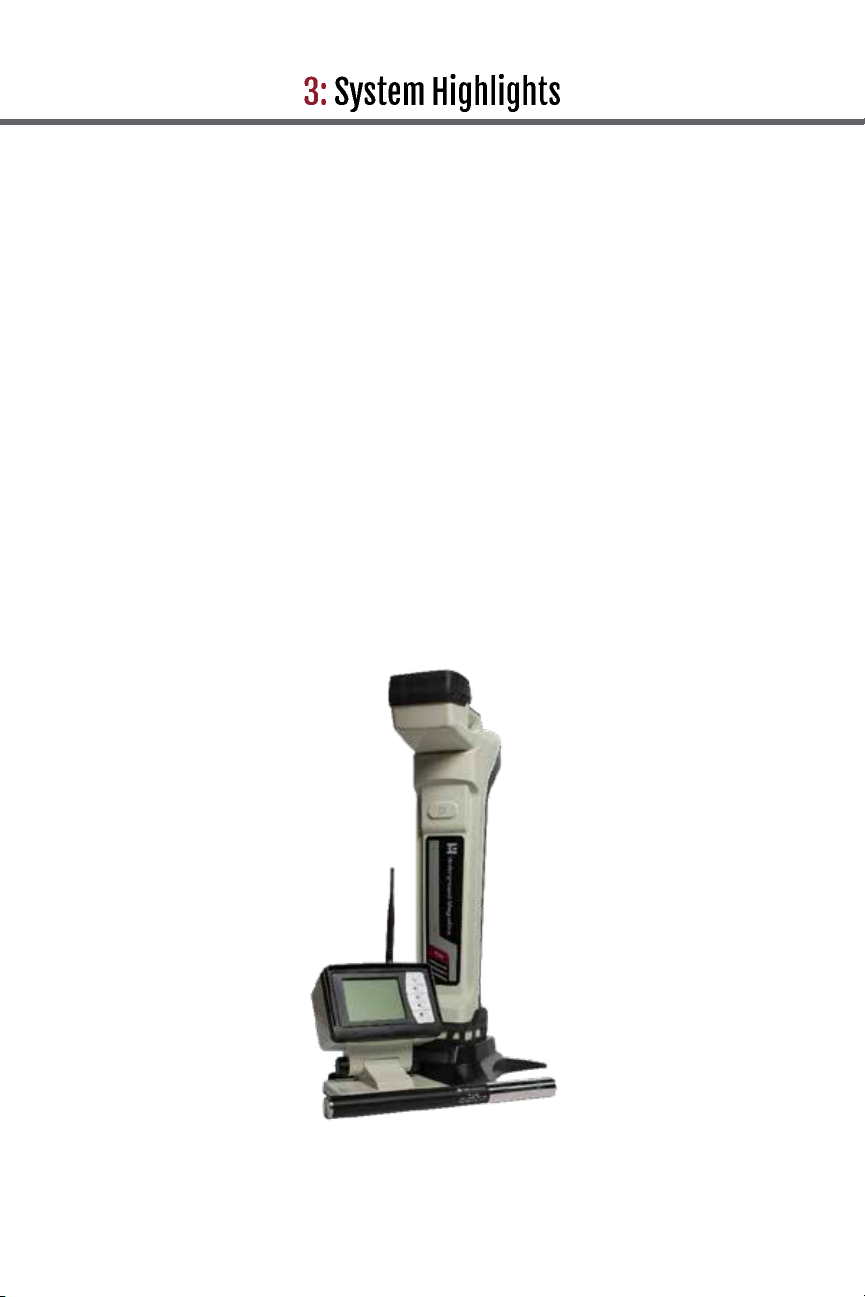
MAG 3 is a locating system designed to assist horizontal
directional drill machine operators in locating and tracking
underground drill head locations and orientations. The
system consists of a transmitter, a receiver, and a remote
display.
The transmitter sends digital information of the
transmitter’s pitch, roll, temperature, and battery
status through an FM modulated RF signal.
The receiver receives this information and uses RF
signal to identify the transmitter’s status and location.
The receiver transmits the locating information to a
remote display through a radio telemetry system. A
horizontal directional drill machine operator can use
the information from the display to guide the drill
head to the desired path.
The FM communication between the transmitter and the
receiver provides more noise suppression than the
traditional AM modulation widely used in this industry.
The receiver offers a very simple and clear method to
locate an underground drill head.
This locating system also offers four channel license free
radio telemetries between the receiver and remote
display. The user can easily register any two receivers
and displays so that communications between the “pair”
will not be interfered by other “pairs”.
This manual is intended to provide information and
instructions on how to use this locating system properly.
Underground Magnetics reserves the right to improve the
locating system and the user manual at any time without
notice.
Page 1

The user must understand safety procedures and
correct operation methods before operating the
HDD and the locating system.
HDD machines can cause property damage and
personal injury upon striking underground power
lines, gas lines, phone lines, television cables, fiber
optic cables, or sewage lines. Make sure to confirm
and mark all underground utilities before beginning
operations.
Do not use the locating system near flammable or
explosive substances.
Wear proper personal protective equipment
including steel-toed boots, safety gloves, helmets,
reflective vests, and safety goggles.
Obey all local safety regulations.
This locating system is only a tool to assist the
operator to locate the drill head. It is the operator,
not the Mag 3 locating system that is responsible for
identifying the drill head location. Underground
Magnetics is not responsible for any damage or loss
caused by using the Mag 3 system. Users should
operate the Mag 3 system according to the manual.
If there are any questions, please contact
Underground Magnetics.
Page 2

High precision and high anti-interference Faraday
shield 3D antenna structure
Industrial rated, gold-plated electronic modules
High-performance DSP
Dual locating system, functioning as two locators
independently tracking to provide better accuracy
and reliability
Up to 160ft depth range and up to 200 hours
continuous usage
Page 3

Mag 3
Power key: Press and hold to turn on or off.
Tap to turn backlight on or off.
Up key: Move to previous cursor selection.
Down key: Move to next cursor selection.
Confirm key: Tap to confirm cursor selection.
Press and hold to enter secondary
page.
Setup key: Tap to enter calibration page/
return to main page. Press and
hold to enter setup page.
System
frequency
4kHz, 19kHz, 30kHz
Water proof IP65
Temperature
range
-4° to 140°F
Telemetry 4 radio channels with
range up to 3000 feet
Rechargeable
lithium battery
12.5V
Battery life Up to 50 hours
Dimensions 27” by 5” by 12”
Weight 6.5 pounds
Page 4

Transmitter model and frequency
Transmitter signal strength
Signal to noise ratio bar
Transmitter battery status
Transmitter temperature (Flashing
indicates transmitter is over-heating)
Receiver and display connection status
Distance between transmitter and receiver
Transmitter pitch
Page 5

To enter the secondary page, press and hold
Transmitter model and frequency
Receiver battery status
Telemetry channel
Page 6

A1
:
10ft calibration
A3:Depth prediction
B1: Transmitter activation
B2: Transmitter settings
B3: Receiver settings
B4: Telemetry selection
B5: Receiver and display
pairing
B6: Roll calibration
B7: Pitch unit selection
B8: Time setting
B9: System lock/unlock
B10: Visibility control
B11: System info
B13: Depth unit selection
Page 7

Warning: Even if the transmitter’s roll, pitch, battery status and
temperature are displayed correctly, calibration may
not be reliable due to a distorted magnetic field.
1. Make sure that the transmitter
is working properly. Place it in
the housing.
2. Place housing containing the
transmitter in a location away
from interference.
3. Set transmitter 10 feet apart from center of housing
to center of receiver as shown.
4. Tap to enter
calibration page.
5. Tap three times to
start 10ft calibration and
wait for calibration to
complete.
7. Calibration complete.
8. Tap to return to main
page.
Page 8

1. Place transmitter housing in a 12
o`clock position.
2. Press and hold to
enter setup page and
tap to select B6
icon.
3. Tap three times to
enter and start roll
calibration and wait for
calibration to complete.
4. Calibration complete.
5. Tap to return to
main page.
Page 9

1. Tap to enter
calibration page and
tap to select A3
icon.
2. Tap to enter
depth forecast page.
Maximum, projected,
and minimum depth
forecast values are
listed on the right
while transmitter
model and frequency
are listed at the top.
Tap to reset
forecast
3. Tap to return to
main page.
Page 10

(Process must be started within 10 minutes after batteries have
been placed in the transmitter.)
1. Press and hold to
enter setup page.
Tap to enter
transmitter activation
page.
2. 1111-1111 is the
transmitter identification
number and 3333-3333 is
the prompt code in the
diagram. Send the
transmitter identification
number and the prompt
code to the dealer. The
dealer will give you an
activation password. Use
and to input
password, tap to
confirm activation.
3. Tap to return to
main page.
Page 11

(Process must be started within 10 minutes after batteries have
been placed in the transmitter.)
.
1. Press and hold to
enter setup page and
tap to select B2 icon.
2. Tap to enter transmitter
settings page. The receiver
and Echo transmitter will
automatically pair. Then tap
or and to select
frequency.
3. Tap to return to
main page.
Page 12

1. Press and hold to
enter setup page.
Tap to select B3
icon.
2. Tap to enter
receiver settings
page. Tap or
and to select
Transmitter model and
frequency.
3. Tap to return to
main page.
Page 13

1. Press and hold to
enter setup page.
Tap to select B4
icon.
2. Tap to enter radio
channel page. Use
or to select radio
channel.
3. Tap to return to
main page.
Page 14

1. Press and hold to
enter setup page.
Tap to select B5
icon.
2. Tap to enter radio
registration page.
Tap to start radio
registration. (It is
required that these last
two steps are performed
on the display at the
same time.)
3. Radio registration
complete.
4. Tap to return to
main page.
Page 15

1. Press and hold
to enter setup page
and tap to select
B7 icon. Tap to
enter pitch unit
selection page.
2. Tap to switch
pitch mode.
3. Tap to return to
main page.
Page 16
Other manuals for Mag 3
1
Other Underground Magnetics Measuring Instrument manuals

Underground Magnetics
Underground Magnetics Mag System User manual

Underground Magnetics
Underground Magnetics Mag 8e User manual

Underground Magnetics
Underground Magnetics MAG 3S User manual

Underground Magnetics
Underground Magnetics Mag 9 User manual

Underground Magnetics
Underground Magnetics MAG Series User manual

Underground Magnetics
Underground Magnetics Mag 6 Series User manual

Underground Magnetics
Underground Magnetics MAG Series User manual

Underground Magnetics
Underground Magnetics MAG 3S User manual