manuals.online logo
Brands
  1. Home
  2. •
  3. Brands
  4. •
  5. Underground Magnetics
  6. •
  7. Measuring Instrument
  8. •
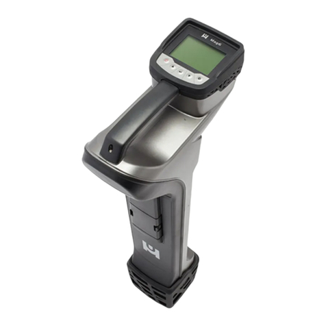
  9. Underground Magnetics Mag 9 User manual

Underground Magnetics Mag 9 User manual

M9 ys
2
Table of Contents
1: Introduction ꞏꞏꞏꞏꞏꞏꞏꞏꞏꞏꞏꞏꞏꞏꞏꞏꞏꞏꞏꞏꞏꞏꞏꞏꞏꞏꞏꞏꞏꞏꞏꞏꞏꞏꞏꞏꞏꞏꞏꞏꞏꞏꞏꞏꞏꞏꞏꞏꞏꞏꞏꞏꞏꞏꞏꞏꞏꞏꞏꞏꞏꞏꞏꞏꞏꞏꞏ page 6
2: Cautionꞏꞏꞏꞏꞏꞏꞏꞏꞏꞏꞏꞏꞏꞏꞏꞏꞏꞏꞏꞏꞏꞏꞏꞏꞏꞏꞏꞏꞏꞏꞏꞏꞏꞏꞏꞏꞏꞏꞏꞏꞏꞏꞏꞏꞏꞏꞏꞏꞏꞏꞏꞏꞏꞏꞏꞏꞏꞏꞏꞏꞏꞏꞏꞏꞏꞏꞏꞏꞏꞏꞏꞏꞏꞏꞏ page 7
3. FCC and CE Compliance ꞏꞏꞏꞏꞏꞏꞏꞏꞏꞏꞏꞏꞏꞏꞏꞏꞏꞏꞏꞏꞏꞏꞏꞏꞏꞏꞏꞏꞏꞏꞏꞏꞏꞏꞏꞏꞏꞏꞏꞏꞏꞏꞏꞏꞏꞏꞏꞏꞏꞏ page 8
4: Manual Tipsꞏꞏꞏꞏꞏꞏꞏꞏꞏꞏꞏꞏꞏꞏꞏꞏꞏꞏꞏꞏꞏꞏꞏꞏꞏꞏꞏꞏꞏꞏꞏꞏꞏꞏꞏꞏꞏꞏꞏꞏꞏꞏꞏꞏꞏꞏꞏꞏꞏꞏꞏꞏꞏꞏꞏꞏꞏꞏꞏꞏꞏꞏꞏꞏꞏꞏꞏꞏꞏ page 9
5: Quick Start ꞏꞏꞏꞏꞏꞏꞏꞏꞏꞏꞏꞏꞏꞏꞏꞏꞏꞏꞏꞏꞏꞏꞏꞏꞏꞏꞏꞏꞏꞏꞏꞏꞏꞏꞏꞏꞏꞏꞏꞏꞏꞏꞏꞏꞏꞏꞏꞏꞏꞏꞏꞏꞏꞏꞏꞏꞏꞏꞏꞏꞏꞏꞏꞏꞏꞏꞏꞏ page 10
6: System Highlightsꞏꞏꞏꞏꞏꞏꞏꞏꞏꞏꞏꞏꞏꞏꞏꞏꞏꞏꞏꞏꞏꞏꞏꞏꞏꞏꞏꞏꞏꞏꞏꞏꞏꞏꞏꞏꞏꞏꞏꞏꞏꞏꞏꞏꞏꞏꞏꞏꞏꞏꞏꞏꞏꞏꞏꞏꞏꞏ page 12
7: Receiver ꞏꞏꞏꞏꞏꞏꞏꞏꞏꞏꞏꞏꞏꞏꞏꞏꞏꞏꞏꞏꞏꞏꞏꞏꞏꞏꞏꞏꞏꞏꞏꞏꞏꞏꞏꞏꞏꞏꞏꞏꞏꞏꞏꞏꞏꞏꞏꞏꞏꞏꞏꞏꞏꞏꞏꞏꞏꞏꞏꞏꞏꞏꞏꞏꞏꞏꞏꞏꞏꞏꞏ page 13
7.1:Specifications ꞏꞏꞏꞏꞏꞏꞏꞏꞏꞏꞏꞏꞏꞏꞏꞏꞏꞏꞏꞏꞏꞏꞏꞏꞏꞏꞏꞏꞏꞏꞏꞏꞏꞏꞏꞏꞏꞏꞏꞏꞏꞏꞏꞏꞏꞏꞏꞏꞏꞏꞏꞏꞏꞏꞏꞏꞏꞏꞏꞏ page 13
7.2: Receiver Operation ꞏꞏꞏꞏꞏꞏꞏꞏꞏꞏꞏꞏꞏꞏꞏꞏꞏꞏꞏꞏꞏꞏꞏꞏꞏꞏꞏꞏꞏꞏꞏꞏꞏꞏꞏꞏꞏꞏꞏꞏꞏꞏꞏꞏꞏꞏꞏꞏꞏꞏꞏꞏ page 13
7.2.1: Measured Depth vs. Relative Depth ꞏꞏꞏꞏꞏꞏꞏꞏꞏꞏꞏꞏꞏꞏꞏꞏꞏꞏꞏꞏꞏꞏꞏꞏꞏꞏꞏꞏ page 14
7.3: Iconsꞏꞏꞏꞏꞏꞏꞏꞏꞏꞏꞏꞏꞏꞏꞏꞏꞏꞏꞏꞏꞏꞏꞏꞏꞏꞏꞏꞏꞏꞏꞏꞏꞏꞏꞏꞏꞏꞏꞏꞏꞏꞏꞏꞏꞏꞏꞏꞏꞏꞏꞏꞏꞏꞏꞏꞏꞏꞏꞏꞏꞏꞏꞏꞏꞏꞏꞏꞏꞏꞏꞏ page 15
7.3.1: Main Page Icons ꞏꞏꞏꞏꞏꞏꞏꞏꞏꞏꞏꞏꞏꞏꞏꞏꞏꞏꞏꞏꞏꞏꞏꞏꞏꞏꞏꞏꞏꞏꞏꞏꞏꞏꞏꞏꞏꞏꞏꞏꞏꞏꞏꞏꞏꞏꞏ page 15
7.3.2: Secondary Page Iconsꞏꞏꞏꞏꞏꞏꞏꞏꞏꞏꞏꞏꞏꞏꞏꞏꞏꞏꞏꞏꞏꞏꞏꞏꞏꞏꞏꞏꞏꞏꞏꞏꞏꞏꞏꞏꞏꞏꞏꞏ page 17
7.3.3: Transmitter Information: ꞏꞏꞏꞏꞏꞏꞏꞏꞏꞏꞏꞏꞏꞏꞏꞏꞏꞏꞏꞏꞏꞏꞏꞏꞏꞏꞏꞏꞏꞏꞏꞏꞏꞏꞏꞏꞏꞏ page 18
7.3.4: Calibration & Depth Forecasting Icons ꞏꞏꞏꞏꞏꞏꞏꞏꞏꞏꞏꞏꞏꞏꞏꞏꞏꞏꞏ page 19
7.3.5: Setup Page Icons ꞏꞏꞏꞏꞏꞏꞏꞏꞏꞏꞏꞏꞏꞏꞏꞏꞏꞏꞏꞏꞏꞏꞏꞏꞏꞏꞏꞏꞏꞏꞏꞏꞏꞏꞏꞏꞏꞏꞏꞏꞏꞏꞏꞏꞏꞏ page 19
7.4:Calibrationꞏꞏꞏꞏꞏꞏꞏꞏꞏꞏꞏꞏꞏꞏꞏꞏꞏꞏꞏꞏꞏꞏꞏꞏꞏꞏꞏꞏꞏꞏꞏꞏꞏꞏꞏꞏꞏꞏꞏꞏꞏꞏꞏꞏꞏꞏꞏꞏꞏꞏꞏꞏꞏꞏꞏꞏꞏꞏꞏꞏꞏꞏꞏꞏꞏ page 20
7.4.1: Depth Calibrationꞏꞏꞏꞏꞏꞏꞏꞏꞏꞏꞏꞏꞏꞏꞏꞏꞏꞏꞏꞏꞏꞏꞏꞏꞏꞏꞏꞏꞏꞏꞏꞏꞏꞏꞏꞏꞏꞏꞏꞏꞏꞏꞏꞏꞏꞏꞏ page 20
7.4.2: Roll Calibration ꞏꞏꞏꞏꞏꞏꞏꞏꞏꞏꞏꞏꞏꞏꞏꞏꞏꞏꞏꞏꞏꞏꞏꞏꞏꞏꞏꞏꞏꞏꞏꞏꞏꞏꞏꞏꞏꞏꞏꞏꞏꞏꞏꞏꞏꞏꞏꞏꞏ page 21
7.5: Operation ꞏꞏꞏꞏꞏꞏꞏꞏꞏꞏꞏꞏꞏꞏꞏꞏꞏꞏꞏꞏꞏꞏꞏꞏꞏꞏꞏꞏꞏꞏꞏꞏꞏꞏꞏꞏꞏꞏꞏꞏꞏꞏꞏꞏꞏꞏꞏꞏꞏꞏꞏꞏꞏꞏꞏꞏꞏꞏꞏꞏꞏꞏꞏꞏꞏ page 22
7.5.1: Depth Forecast ꞏꞏꞏꞏꞏꞏꞏꞏꞏꞏꞏꞏꞏꞏꞏꞏꞏꞏꞏꞏꞏꞏꞏꞏꞏꞏꞏꞏꞏꞏꞏꞏꞏꞏꞏꞏꞏꞏꞏꞏꞏꞏꞏꞏꞏꞏꞏꞏꞏ page 22
7.5.2: Transmitter Lock/Unlockꞏꞏꞏꞏꞏꞏꞏꞏꞏꞏꞏꞏꞏꞏꞏꞏꞏꞏꞏꞏꞏꞏꞏꞏꞏꞏꞏꞏꞏꞏꞏꞏꞏꞏꞏꞏꞏꞏ page 23
7.5.3: Transmitter Settings ꞏꞏꞏꞏꞏꞏꞏꞏꞏꞏꞏꞏꞏꞏꞏꞏꞏꞏꞏꞏꞏꞏꞏꞏꞏꞏꞏꞏꞏꞏꞏꞏꞏꞏꞏꞏꞏꞏꞏꞏꞏꞏꞏ page 24
7.5.4: Receiver Settings ꞏꞏꞏꞏꞏꞏꞏꞏꞏꞏꞏꞏꞏꞏꞏꞏꞏꞏꞏꞏꞏꞏꞏꞏꞏꞏꞏꞏꞏꞏꞏꞏꞏꞏꞏꞏꞏꞏꞏꞏꞏꞏꞏꞏꞏꞏ page 25
7.5.5: Radio Channel Selectionꞏꞏꞏꞏꞏꞏꞏꞏꞏꞏꞏꞏꞏꞏꞏꞏꞏꞏꞏꞏꞏꞏꞏꞏꞏꞏꞏꞏꞏꞏꞏꞏꞏꞏꞏꞏꞏ page 27
7.5.6: Receiver and Display Pairing ꞏꞏꞏꞏꞏꞏꞏꞏꞏꞏꞏꞏꞏꞏꞏꞏꞏꞏꞏꞏꞏꞏꞏꞏꞏꞏꞏꞏꞏꞏꞏ page 28
3
Table of Contents
7.5.7: Pitch Unit Selection ꞏꞏꞏꞏꞏꞏꞏꞏꞏꞏꞏꞏꞏꞏꞏꞏꞏꞏꞏꞏꞏꞏꞏꞏꞏꞏꞏꞏꞏꞏ page 29
7.5.8: Distance Unit Selection ꞏꞏꞏꞏꞏꞏꞏꞏꞏꞏꞏꞏꞏꞏꞏꞏꞏꞏꞏꞏꞏꞏꞏꞏꞏ page 30
7.5.9: Time Settingꞏꞏꞏꞏꞏꞏꞏꞏꞏꞏꞏꞏꞏꞏꞏꞏꞏꞏꞏꞏꞏꞏꞏꞏꞏꞏꞏꞏꞏꞏꞏꞏꞏꞏꞏꞏꞏꞏꞏꞏ page 31
7.5.10: Manual System Lock/Unlockꞏꞏꞏꞏꞏꞏꞏꞏꞏꞏꞏꞏꞏꞏꞏꞏꞏ page 32
7.5.11: Ball Speed Controlꞏꞏꞏꞏꞏꞏꞏꞏꞏꞏꞏꞏꞏꞏꞏꞏꞏꞏꞏꞏꞏꞏꞏꞏꞏꞏꞏꞏꞏꞏ page 33
7.5.12: Depth Speed Adjustment ꞏꞏꞏꞏꞏꞏꞏꞏꞏꞏꞏꞏꞏꞏꞏꞏꞏꞏꞏꞏꞏ page 34
7.6: Receiver Maintenanceꞏꞏꞏꞏꞏꞏꞏꞏꞏꞏꞏꞏꞏꞏꞏꞏꞏꞏꞏꞏꞏꞏꞏꞏꞏꞏꞏꞏꞏꞏꞏꞏꞏꞏꞏ page 35
8: Displayꞏꞏꞏꞏꞏꞏꞏꞏꞏꞏꞏꞏꞏꞏꞏꞏꞏꞏꞏꞏꞏꞏꞏꞏꞏꞏꞏꞏꞏꞏꞏꞏꞏꞏꞏꞏꞏꞏꞏꞏꞏꞏꞏꞏꞏꞏꞏꞏꞏꞏꞏꞏꞏꞏꞏꞏꞏꞏꞏꞏ page 36
8.1: Display Specifications ꞏꞏꞏꞏꞏꞏꞏꞏꞏꞏꞏꞏꞏꞏꞏꞏꞏꞏꞏꞏꞏꞏꞏꞏꞏꞏꞏꞏꞏꞏꞏꞏꞏꞏꞏ page 36
8.2: Display Operations ꞏꞏꞏꞏꞏꞏꞏꞏꞏꞏꞏꞏꞏꞏꞏꞏꞏꞏꞏꞏꞏꞏꞏꞏꞏꞏꞏꞏꞏꞏꞏꞏꞏꞏꞏꞏꞏꞏꞏ page 36
8.3: Display Iconsꞏꞏꞏꞏꞏꞏꞏꞏꞏꞏꞏꞏꞏꞏꞏꞏꞏꞏꞏꞏꞏꞏꞏꞏꞏꞏꞏꞏꞏꞏꞏꞏꞏꞏꞏꞏꞏꞏꞏꞏꞏꞏꞏꞏꞏꞏꞏ page 37
8.3.1: Main Page Icons ꞏꞏꞏꞏꞏꞏꞏꞏꞏꞏꞏꞏꞏꞏꞏꞏꞏꞏꞏꞏꞏꞏꞏꞏꞏꞏꞏꞏꞏꞏꞏꞏꞏꞏ page 37
8.4: Down Hole Frequency Changeꞏꞏꞏꞏꞏꞏꞏꞏꞏꞏꞏꞏꞏꞏꞏꞏꞏꞏꞏꞏꞏꞏꞏꞏ page 39
8.5: Radio Telemetry Channel Selectionꞏꞏꞏꞏꞏꞏꞏꞏꞏꞏꞏꞏꞏꞏꞏꞏꞏꞏ page 41
8.6: Receiver & Display Pairing ꞏꞏꞏꞏꞏꞏꞏꞏꞏꞏꞏꞏꞏꞏꞏꞏꞏꞏꞏꞏꞏꞏꞏꞏꞏꞏꞏꞏꞏ page 42
8.7: Brightness Adjustmentꞏꞏꞏꞏꞏꞏꞏꞏꞏꞏꞏꞏꞏꞏꞏꞏꞏꞏꞏꞏꞏꞏꞏꞏꞏꞏꞏꞏꞏꞏꞏꞏꞏꞏꞏ page 43
8.8: Bore Log ꞏꞏꞏꞏꞏꞏꞏꞏꞏꞏꞏꞏꞏꞏꞏꞏꞏꞏꞏꞏꞏꞏꞏꞏꞏꞏꞏꞏꞏꞏꞏꞏꞏꞏꞏꞏꞏꞏꞏꞏꞏꞏꞏꞏꞏꞏꞏꞏꞏꞏꞏꞏ page 44
8.8.1: Job Management ꞏꞏꞏꞏꞏꞏꞏꞏꞏꞏꞏꞏꞏꞏꞏꞏꞏꞏꞏꞏꞏꞏꞏꞏꞏꞏꞏꞏꞏꞏꞏꞏꞏ page 44
8.8.2: Creating a New Job Profileꞏꞏꞏꞏꞏꞏꞏꞏꞏꞏꞏꞏꞏꞏꞏꞏꞏꞏꞏꞏꞏ page 44
8.8.3: Setting the Rod Lengths ꞏꞏꞏꞏꞏꞏꞏꞏꞏꞏꞏꞏꞏꞏꞏꞏꞏꞏꞏꞏꞏꞏꞏꞏ page 45
8.8.4: Data Logging ꞏꞏꞏꞏꞏꞏꞏꞏꞏꞏꞏꞏꞏꞏꞏꞏꞏꞏꞏꞏꞏꞏꞏꞏꞏꞏꞏꞏꞏꞏꞏꞏꞏꞏꞏꞏꞏꞏ page 46
8.8.5: Bore Profileꞏꞏꞏꞏꞏꞏꞏꞏꞏꞏꞏꞏꞏꞏꞏꞏꞏꞏꞏꞏꞏꞏꞏꞏꞏꞏꞏꞏꞏꞏꞏꞏꞏꞏꞏꞏꞏꞏꞏꞏꞏ page 47
8.8.6: Data Point Information Screen ꞏꞏꞏꞏꞏꞏꞏꞏꞏꞏꞏꞏꞏꞏꞏꞏ page 47
8.8.7: Generating Reports ꞏꞏꞏꞏꞏꞏꞏꞏꞏꞏꞏꞏꞏꞏꞏꞏꞏꞏꞏꞏꞏꞏꞏꞏꞏꞏꞏꞏꞏꞏ page 48
4
Table of Contents
8.9: Device Management ꞏꞏꞏꞏꞏꞏꞏꞏꞏꞏꞏꞏꞏꞏꞏꞏꞏꞏꞏꞏꞏꞏꞏꞏꞏꞏꞏꞏꞏꞏꞏꞏꞏꞏꞏꞏꞏꞏꞏꞏ page 49
8.9.1: Automatic Receiver Unlock ꞏꞏꞏꞏꞏꞏꞏꞏꞏꞏꞏꞏꞏꞏꞏꞏꞏꞏꞏꞏꞏꞏꞏꞏꞏꞏ page 50
8.9.2: Automatic Transmitter Unlock ꞏꞏꞏꞏꞏꞏꞏꞏꞏꞏꞏꞏꞏꞏꞏꞏꞏꞏꞏꞏꞏꞏꞏ page 51
8.10: Display Settingsꞏꞏꞏꞏꞏꞏꞏꞏꞏꞏꞏꞏꞏꞏꞏꞏꞏꞏꞏꞏꞏꞏꞏꞏꞏꞏꞏꞏꞏꞏꞏꞏꞏꞏꞏꞏꞏꞏꞏꞏꞏꞏꞏꞏꞏ page 52
8.11: Help ꞏꞏꞏꞏꞏꞏꞏꞏꞏꞏꞏꞏꞏꞏꞏꞏꞏꞏꞏꞏꞏꞏꞏꞏꞏꞏꞏꞏꞏꞏꞏꞏꞏꞏꞏꞏꞏꞏꞏꞏꞏꞏꞏꞏꞏꞏꞏꞏꞏꞏꞏꞏꞏꞏꞏꞏꞏꞏꞏꞏ page 53
8.12: Display Maintenance ꞏꞏꞏꞏꞏꞏꞏꞏꞏꞏꞏꞏꞏꞏꞏꞏꞏꞏꞏꞏꞏꞏꞏꞏꞏꞏꞏꞏꞏꞏꞏꞏꞏꞏꞏꞏꞏꞏ page 54
9: Transmitter ꞏꞏꞏꞏꞏꞏꞏꞏꞏꞏꞏꞏꞏꞏꞏꞏꞏꞏꞏꞏꞏꞏꞏꞏꞏꞏꞏꞏꞏꞏꞏꞏꞏꞏꞏꞏꞏꞏꞏꞏꞏꞏꞏꞏꞏꞏꞏꞏꞏꞏꞏꞏꞏꞏ page 55
9.1: Introduction ꞏꞏꞏꞏꞏꞏꞏꞏꞏꞏꞏꞏꞏꞏꞏꞏꞏꞏꞏꞏꞏꞏꞏꞏꞏꞏꞏꞏꞏꞏꞏꞏꞏꞏꞏꞏꞏꞏꞏꞏꞏꞏꞏꞏꞏꞏꞏꞏꞏ page 55
9.2: Specifications ꞏꞏꞏꞏꞏꞏꞏꞏꞏꞏꞏꞏꞏꞏꞏꞏꞏꞏꞏꞏꞏꞏꞏꞏꞏꞏꞏꞏꞏꞏꞏꞏꞏꞏꞏꞏꞏꞏꞏꞏꞏꞏpage 56-59
9.3: Digital Information ꞏꞏꞏꞏꞏꞏꞏꞏꞏꞏꞏꞏꞏꞏꞏꞏꞏꞏꞏꞏꞏꞏꞏꞏꞏꞏꞏꞏꞏꞏꞏꞏꞏꞏꞏꞏꞏꞏꞏꞏ page 60
10: Locating Methods ꞏꞏꞏꞏꞏꞏꞏꞏꞏꞏꞏꞏꞏꞏꞏꞏꞏꞏꞏꞏꞏꞏꞏꞏꞏꞏꞏꞏꞏꞏꞏꞏꞏꞏꞏꞏꞏꞏꞏꞏꞏꞏꞏ page 61
10.1: Three Point Locating ꞏꞏꞏꞏꞏꞏꞏꞏꞏꞏꞏꞏꞏꞏꞏꞏꞏꞏꞏꞏꞏꞏꞏꞏꞏꞏꞏꞏꞏꞏꞏꞏꞏꞏꞏ page 61
10.1.1: The Basics ꞏꞏꞏꞏꞏꞏꞏꞏꞏꞏꞏꞏꞏꞏꞏꞏꞏꞏꞏꞏꞏꞏꞏꞏꞏꞏꞏꞏꞏꞏꞏꞏꞏꞏꞏꞏꞏꞏꞏꞏ page 61
10.1.2: Find the Transmitter ꞏꞏꞏꞏꞏꞏꞏꞏꞏꞏꞏꞏꞏꞏꞏꞏꞏꞏꞏꞏꞏꞏꞏꞏꞏꞏꞏꞏ page 64
10.1.3: Tracking on the Fly: ꞏꞏꞏꞏꞏꞏꞏꞏꞏꞏꞏꞏꞏꞏꞏꞏꞏꞏꞏꞏꞏꞏꞏꞏꞏꞏꞏꞏ page 67
10.1.4: Bore-To ꞏꞏꞏꞏꞏꞏꞏꞏꞏꞏꞏꞏꞏꞏꞏꞏꞏꞏꞏꞏꞏꞏꞏꞏꞏꞏꞏꞏꞏꞏꞏꞏꞏꞏꞏꞏꞏꞏꞏꞏꞏꞏꞏꞏ page 68
11: Battery and Charger ꞏꞏꞏꞏꞏꞏꞏꞏꞏꞏꞏꞏꞏꞏꞏꞏꞏꞏꞏꞏꞏꞏꞏꞏꞏꞏꞏꞏꞏꞏꞏꞏꞏꞏꞏꞏꞏꞏꞏꞏ page 69
12: Warranty ꞏꞏꞏꞏꞏꞏꞏꞏꞏꞏꞏꞏꞏꞏꞏꞏꞏꞏꞏꞏꞏꞏꞏꞏꞏꞏꞏꞏꞏꞏꞏꞏꞏꞏꞏꞏꞏꞏꞏꞏꞏꞏꞏꞏꞏꞏꞏꞏꞏꞏꞏꞏꞏꞏꞏꞏ page 70
5
This locating system also offers four channel license free
radio telemetries between the receiver and remote
display. The user can easily “pair” any two receivers and
displays so that communications between the “pair” will
not be interfered by other “pairs”.
This manual is intended to provide information and
instructions on how to use this locating system properly.
Underground Magnetics Inc. (UM) reserves the right to
improve the locating system and the Operator’s Manual at
any time without notice.
MAG 9 SYSTEM
6
RECEIVER
The Transmitter (sometimes referred to as a Sonde or
Beacon) sends digital information of the transmitters pitch,
roll, temperature and battery status through an FM
modulated RF signal.
The Receiver receives this information and uses RF Signal to
identify the transmitter’s status and location.
The Display— the Receiver transmits the locating information
to the remote display through a radio telemetry system.
A horizontal directional drilling machine operator can use the
information from the display to the guide the drill head to the
desired location. path.
1: Introduction
TRANSMITTER
DISPLAY
7
The operator must understand safety procedures
and correct operation methods before operating the
HDD and the locating system.
Do not use the locating system near flammable or
explosive substances.
Wear proper personal protective equipment
including steel-toed boots, safety gloves, helmets,
reflective vests, and safety goggles.
Obey all local safety regulations.
This locating system is only a tool to assist the
operator to locate the drill head. It is the operator,
not the Mag locating system that is responsible
for identifying the drill head location. UM is not
responsible for any damage or loss caused by using
the Mag system. Operators should operate the
Mag system according to the manual.
2: Caution
If there are any questions, please contact UM at
[email protected] or call customer
service at (515) 505-0960
HDD machines can cause property damage and
personal injury upon striking underground power
lines, gas lines, phone lines, television cables, fiber
optic cables, or sewage lines. Make sure to confirm
by uncovering and marking all underground utilities
before crossing.
8
This device complies with Part 15 of the FSS Rules. Operation is
subject to the following two conditions:
 This device may not cause harmful interference, and
 This device must accept any interference received ,including
interference that may cause undesired operation.
Changes or modifications not expressly approved by Under-
ground Magnetics Inc. will void the user’s authority to operate
equipment.
Note: This product has been tested and found to comply with the limits
for a Class B digital device, pursuant to Part 15 of the FCC Rules.
These limits are designed to provide reasonable protection against
harmful interference in a residential installation. This product
generates, uses and can radiate radio frequency energy, and if not
installed and used in accordance with the instructions, may cause
harmful interference to radio communications. However, there is no
guarantee that interference will not occur in a particular installation. If
this product does cause harmful interference to radio or television
reception, which can be determined by turning the equipment off and
on, the user is encouraged to try to correct the interference by one or
more of the following measures:
 Reorient or relocate the receiving antenna .
 Increase the separation between the equipment and the receiver.
 Connect the equipment into an outlet on a circuit different from that
to which the receiver is connected.
 Consult the dealer or an experienced radio/TV technician for help.
3: FCC and CE
This system is classified as Class 2 radio equipment per the R & TTE
Directive and may not be legal to operate or require a license to operate
in some countries. The list of restrictions and the required declarations
of conformity are available in the “resources” section of the UM website.
9
4: Tips for Reading this Manual
Here are some points to keep in mind as you read through the
Mag 9 Operator’s Manual.
Page References
This question mark and textbox will
tell you the page in the Operator’s
Manual where you can find more
detailed information on the corre-
sponding topic.
Page X
The following two pages contain a short preface. This
will be a quick introduction to the steps in which you will
most likely use your Mag System. It will also contain
page references for the later sections of the manual that
contain more detailed information for the corresponding
steps.
The rest of the manual will contain detailed sections that
follow the order of the Mag 9 Receiver and the Mag 9
menu screens
It is recommended to read the entire Operator’s Manual
before use.
Throughout this manual there will be
scannable QR codes that link to our training
videos. Be sure to check those out for
additional details!
10
5: Quick Start
1Turn on receiver by holding power button
until Mag logo is visible on screen Page 14
2
3
4
5
Walk bore-path and use depth
forecasting to check for interference and
select frequency.
Page 22
Install batteries into transmitter. Install
battery cap with provided battery cap
tool.
Turn on display by holding power button
until Mag logo is visible on the screen
Install transmitter into the housing.
11
6
7
9
8
10
Check Calibration by placing receiver
(10ft/3m) away from housing, measured
from inside edge of receiver to the center
of the housing.
Page 64
Page 20
Page 64
Page 63
If distance on receiver’s screen reads
anything other than (10ft/3m) perform
calibration.
Choose locating mode either Single
Point or Single Ball.
Locate FLP (Front Locate Point).
Locate RLP (Rear Locate Point).
11 Locate LL (Locate Line).
Repeat steps 9 through 11 as you
continue to guide the drill.
Page 64
12
6: System Highlights
Mag 9 System
High Precision and high anti-interference Faraday shield 3D antenna
structure.
Display features 7” color touch screen
High-performance DSP
Dual locating system, functioning as two receivers independently
tracking to provide better accuracy and reliability
Locating Method—choose Single Point or Single Ball Mode
ECHO 110
ECHO 60
ECHO 50
ECHO 90
ECHO 50XF
ECHO ST
ECHO 70
ECHO 50X
ECHO XMINI
Mag 9 Transmitters:
Receiver : Mag 9
Display : Mag 9
Display features a Built-in Data Logging System
13
7: Receiver
7.1: Specifications
battery
16 System frequencies
.325kHz – 41kHz
Temperature range -4° to 140°F (-20° to 60°c)
Water resistant IP65
Telemetry 4 radio channels with
range up to 3000ft (900m)*
Rechargeable lithium 12.5V
Battery life Up to 50 hours
Dimensions 29” x 9” x 13” (73.5cm x 23cm x 33cm)
Weight 8.5 lbs (3.85 kg)
7.2: Receiver Operation
 Press and hold to turn on or off.
 In the menu, move to previous cursor selection.
 From main page, tap to switch between relative
depth and measured depth. See page 14
 In the menu, tap to move to next cursor selection.
 From main page, tap to record Bore data.
See page 43
 Tap to confirm cursor selection.
 Press and hold to enter secondary page.
 Tap from main page to enter Bore-To mode.
 Tap to enter calibration page/return to main page.
 Press and hold to enter the menu screen.
* With opƟonal Yagi Antenna
Up key:
Down key:
Confirm key:
Setup key:
Power key:
14
1. From the main locating screen, tap to switch between
Measured Depth and Relative Depth as highlighted above.
This feature is only available when recording Bore-Log data
See Page 43 for Bore-Log instructions
7: Receiver
7.2.1: Measured Depth vs. Relative Depth
 Measured Depth - This is the measured distance
between the locator and the transmitter located inside
the drill head.
 Relative Depth - This information is measured
based on the pitch of the transmitter/housing.
 This measurement is the depth of the transmitter/
housing in relation to the starting point of the bore.
In this example, the transmitter is 2’5” deep in relation
to where the first data point was recorded at the start
of the bore.
15
7: Receiver
7.3.1: Main Page Icons
7.3: Icons
Transmitter model, frequency, and power
Signal to Noise Ratio
Signal strength
Visual representation of signal to noise
Transmitter temperature (flashing indicates the
transmitter is overheating)
Depth when over the head
Receiver remote telemetry indicator
Rod Counter
16
Clock positions
Pitch
Roll indicator
Locate Line
To select locating modes see section 10.1.1
Direction of nearest
Locate Point
Single Point Single Ball
17
7.3.2: Secondary Page Icons
To enter the secondary Page, press and hold
Radio Channel
Receiver Battery Status
Transmitter Model, frequency
and power
Tap to view transmiƩer informaƟon
18
7.3.3: Transmitter Information
Transmitter Model, Frequency and Power level
Transmitter battery voltage meter
Transmitter antenna health.
(Normal range 95% to 105%)
From secondary page, tap to view transmitter information page
Transmitter Housing suitability.
Note:
Normal Power Mode below 800mW
High Power Mode below 3000mW
(Numbers above mW will see lower battery life).
19
7.3.4: Calibration and Depth Forecast Page Icons
A1: 10ft calibration
A4: 66ft calibration
A2: 33ft calibration
A5: Depth Forecast
7.3.5: Setup Page Icons B1:
B2:
B3:
B4:
B5:
B6:
B7:
B8:
B9:
B10:
B11:
B13:
B16:
B20:
B23:
B26:
TransmiƩer lock/unlock
TransmiƩer seƫngs
Receiver seƫngs
Radio channel selecƟon
Receiver and Display pairing
Roll calibraƟon
Pitch and unit selecƟon
Time seƫng
System lock/unlock
Visibility control
System informaƟon
Distance and unit selecƟon
Speed Control
TransmiƩer InformaƟon
LocaƟng Mode
Depth Speed
20
7.4: Calibration
7.4.1: Depth Calibration
Do not calibrate around strong active or passive interference.
For example, don’t calibrate around an electrical transformer (active), or on
concrete with rebar and/or wire mesh (passive). These types of areas can
effect the depth calibration and accuracy significantly.
1. Place transmitter inside housing flat on the ground.
2. Measure from the center of the housing, 10’ to the
inside edge of the locator.
3. Tap to enter calibration screen.
Tap to enter calibration page.
4. Tap twice more to begin calibration.
Check mark will show when complete.
Note: Calibrate at 10ft first before calibrating at 33ft or 66ft. Calibrating at 33ft or 66ft is
not necessary unless drilling at extreme depths.
Above ground calibration check:
Once calibration is completed, press button to return
to main screen. 10ft will be displayed in the upper left
hand portion of the screen.
To check quality of calibration, move locator out 20’
from housing and check distance. If calibration is cor-
rect, distance should be within 1”.
After calibration, above ground distance will change to below ground distance. Below ground
distance is the distance to the transmitter or, the depth when directly above the transmitter. This
conversion is done automatically when the transmitter has rotated for 15 seconds.
ABOVE GROUND DISTANCE BELOW GROUND DISTANCE

Other Underground Magnetics Measuring Instrument manuals

Underground Magnetics Mag System User manual

Underground Magnetics

Underground Magnetics Mag System User manual

Underground Magnetics Mag 6 Series User manual

Underground Magnetics

Underground Magnetics Mag 6 Series User manual

Underground Magnetics Mag 8e User manual

Underground Magnetics

Underground Magnetics Mag 8e User manual

Underground Magnetics MAG 3S User manual

Underground Magnetics

Underground Magnetics MAG 3S User manual

Underground Magnetics MAG 3S User manual

Underground Magnetics

Underground Magnetics MAG 3S User manual

Underground Magnetics MAG Series User manual

Underground Magnetics

Underground Magnetics MAG Series User manual

Underground Magnetics Mag 3 User manual

Underground Magnetics

Underground Magnetics Mag 3 User manual

Underground Magnetics MAG Series User manual

Underground Magnetics

Underground Magnetics MAG Series User manual

Popular Measuring Instrument manuals by other brands

Hanna Instruments Checker HI 723 quick start guide

Hanna Instruments

Hanna Instruments Checker HI 723 quick start guide

BH FITNESS H673 manual

BH FITNESS

BH FITNESS H673 manual

Eaton IQ 35M Series quick start guide

Eaton

Eaton IQ 35M Series quick start guide

AEMC MN379 user manual

AEMC

AEMC MN379 user manual

Datamarine Corinthian Series owner's manual

Datamarine

Datamarine Corinthian Series owner's manual

Omron K3MA-J Series manual

Omron

Omron K3MA-J Series manual

Würth DS 350 Translation of the original operating instructions

Würth

Würth DS 350 Translation of the original operating instructions

Megger DLRO 200 user guide

Megger

Megger DLRO 200 user guide

Philips GoSure ADR730 user manual

Philips

Philips GoSure ADR730 user manual

Anaheim Scientific E100 user manual

Anaheim Scientific

Anaheim Scientific E100 user manual

Bushnell GOLF HYBRID user manual

Bushnell GOLF

Bushnell GOLF HYBRID user manual

Farnell Sound level meter instruction manual

Farnell

Farnell Sound level meter instruction manual

LINSHANG LS232 user manual

LINSHANG

LINSHANG LS232 user manual

EKF Quo-Test user manual

EKF

EKF Quo-Test user manual

Triplett PQC300 user manual

Triplett

Triplett PQC300 user manual

Shodex IEC QA-825 Operation manual

Shodex

Shodex IEC QA-825 Operation manual

SPM A2010 instruction manual

SPM

SPM A2010 instruction manual

Vetek JIK-6 Series Service manual

Vetek

Vetek JIK-6 Series Service manual

manuals.online logo
manuals.online logoBrands
  • About & Mission
  • Contact us
  • Privacy Policy
  • Terms and Conditions

Copyright 2025 Manuals.Online. All Rights Reserved.