Uniblitz N-CAS VINCENT ASSOCIATES VLM1 User manual

User Manual
VLM1/VLM1B Interface Module
For the FS Shutter Series
14-0055
Version 1.01
2021
1.800.828.6972

VLM1/VLM1B User Manual
2
For information regarding applicable intellectual property, please visit www.uniblitz.com/patents.
For WARRANTY information please visit https://www.uniblitz.com/terms/
Information in this publication supersedes that in all previously published material. Due to our ongoing
development program, Vincent Associates reserves the right to discontinue or change specifications or
designs, at any time, without incurring any obligation.
Revision Table
Version 1.00 - 2020
10/21/20 STP Initial release – Rev b
Version 1.01 - 2021
3/23/21 STP Minor revisions – Rev c
Vincent Associates, a Division of VA, Inc.
803 Linden Ave.
Rochester, NY 14625
Tel: 585-385-5930
Fax: 585-385-6004
UNIBLITZ, N-CAS and VINCENT ASSOCIATES are registered trademarks of VA, Inc.
Printed in the U.S.A.

VLM1/VLM1B User Manual
3
TableofContents
TABLE OF FIGURES ...................................................................................... 4
GENERAL SAFETY SUMMARY .................................................................. 5
Injury Precautions ...................................................................................................... 5
Product Damage Precautions .................................................................................... 5
Safety Terms and Symbols ........................................................................................ 6
PREFACE .......................................................................................................... 6
GETTING STARTED ...................................................................................... 7
Features ....................................................................................................................... 7
Introduction ................................................................................................................ 8
OPERATOR CONTROLS............................................................................... 9
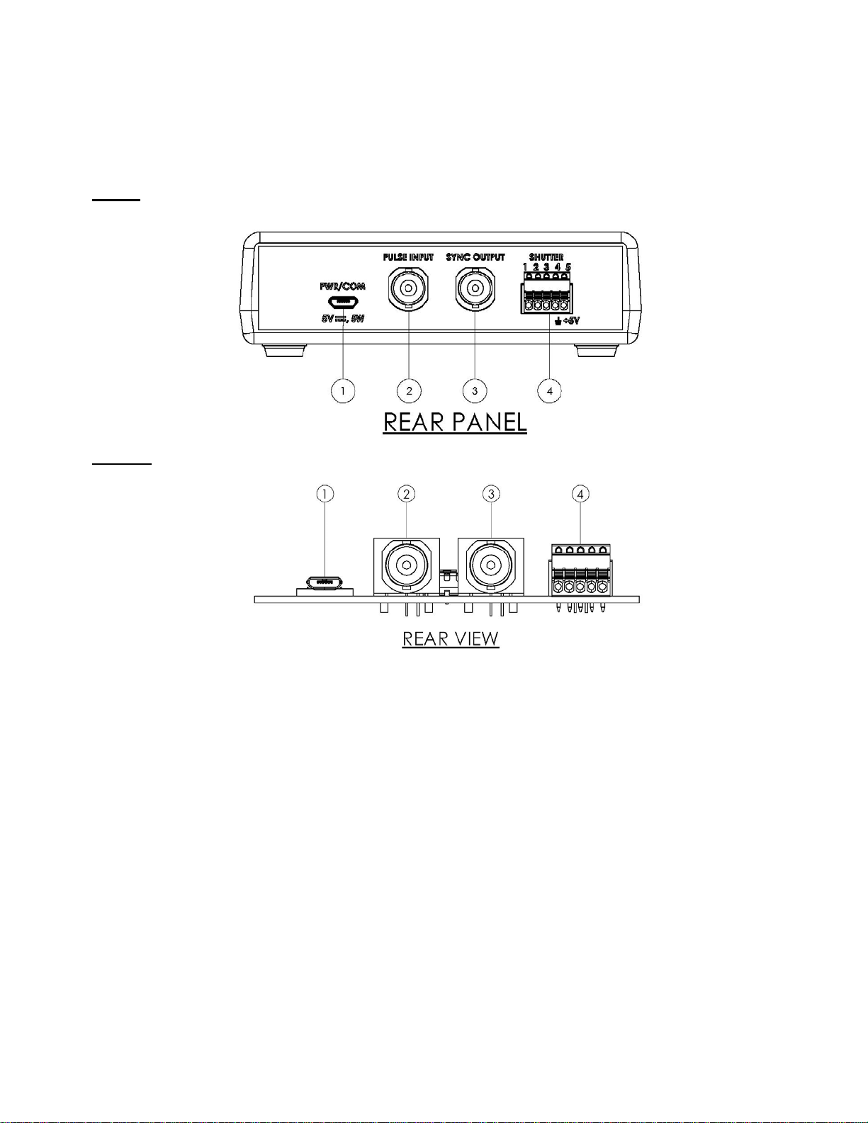
VLM1/VLM1B Rear Panel Operator Connections ................................................ 9
VLM1/VLM1B Front Panel Operator Controls/Indicators ................................. 10
Start Up ..................................................................................................................... 1 1
Extending the Shutter Interconnection .................................................................. 11
Terminal Block Wire Installation ........................................................................... 12
OPERATING BASICS ................................................................................... 14
Initial Operation and Testing .................................................................................. 14
BNC I/O Active State Selection ............................................................................... 15
Fuse Information ...................................................................................................... 15
USB Operation .......................................................................................................... 18
Maintenance .............................................................................................................. 18
Inspection 18
Cleaning Procedure 18
SPECIFICATIONS ......................................................................................... 19
System Characteristics ............................................................................................. 19
External Input Characteristics ............................................................................... 19
External Output Characteristics ............................................................................. 20
General Characteristics ........................................................................................... 20

VLM1/VLM1B User Manual
4
NOTES ............................................................................................................. 23
Table of Figures
Figure 1: 5-Pin Pluggable Phoenix Connector ....................................................................................... 7
Figure 2: VLM1/VLM1B Rear Panel/View Layout ............................................................................... 9
Figure 3: VLM1/VLM1B Front Panel/View Layout ........................................................................... 10
Figure 4: VLM1/VLM1B SHUTTER Wire Installation Diagram ..................................................... 12
Figure 5: VLM1 to FS Series Shutter - Interconnection Diagram ..................................................... 13
Figure 6: VLM1 Dimensional Layout ................................................................................................... 16
Figure 7: VLM1B Dimensional Layout - Fuse/Jumper Locations ..................................................... 17
Figure 8: VLM1/VLM1B Schematic Diagram ..................................................................................... 22

VLM1/VLM1B User Manual
5
General Safety Summary
Review the following safety precautions to avoid injury and prevent damage to this product or any
products connected to it. To avoid potential hazards, use the product only as specified.
Only qualified personnel should perform service procedures.
Injury Precautions
Avoid Electric Overload – To avoid electrical shock or fire hazard, do not apply a voltage to a
terminal that is outside the range specified for that terminal.
Avoid Electric Shock – To avoid injury or loss of life, do not connect or disconnect line cord
while it is connected to the line voltage.
Ground the Product – This product can be grounded through the SHUTTER connector, Pin #4
if required.
Use Proper Fuse – To avoid fire hazard, use only the fuse type and rating specified for this
product. The VLM1/VLM1B contain no user replaceable fuses.
Do Not operate in Wet/Damp Conditions – To avoid electric shock, do not operate this product
in wet or damp conditions.
Do Not Operate in an Explosive Atmosphere – To avoid injury or fire hazard, do not operate
this product in an explosive atmosphere.
Product Damage Precautions
Use Proper Power Source – Do not operate this product from a power source that applies more
than the voltage specified.
Provide Proper Ventilation – To prevent product overheating, provide proper ventilation.
Do Not Operate with Suspected Failures – If you suspect there is damage to this product, have
it inspected by qualified service personnel.

VLM1/VLM1B User Manual
6
Safety Terms and Symbols
These terms appear in this manual.
Preface
This Manual provides information for the VLM1/VLM1B Interface Module. The manual contains the
following chapters:
Getting Started contains a brief product description, information needed to power on the driver
and a brief procedure to verify that it functions.
Operating Basics gives further details to the operational features of the driver.
Specifications are described for all input/output controls as well as operational features of the
VLM1/VLM1B.
What follows is the complete operator’s manual for the UNIBLITZVLM1/VLM1B Interface Module.
Please read this manual completely before operating the unit. Due to the construction of this unit,
Vincent Associates recommends that the unit be returned to the manufacturer for repair. There are no
user-serviceable parts.
CAUTION
Warning statements identify conditions or practices that
could result in injury or loss of life.
Caution statements identify conditions or practices that
could result in damage to this product or other property.
WARNING

VLM1/VLM1B User Manual
7
Getting Started
Features
Two different models available – the VLM1, this unit is housed and comes equipped with a
Power Supply, USB/Power Cable, and Accessories. The VLM1B is an open frame printed
circuit card suitable for OEM applications, the only accessory included is a 2mm micro
screwdriver (also included with the VLM1). If required, the power supply and cable can be
purchased separately for the VLM1B.
RoHS Compliant
Designed to provide a convenient device to interface the FS Shutter series to TTL signals or
provide control through a USB com port.
5-Pin Phoenix Contact pluggable, spring cage type, SHUTTER interface connector. Wires are
easily inserted into the connector using a small 2mm screwdriver, included. Dimension “a” is
10mm. See Figure #4 for the shutter wire installation procedure.
Figure 1: 5-Pin Pluggable Phoenix Connector
Exposure determined by external pulse width (BNC,+5V TTL active-high/active-low selectable
by board jumper)
Internal fuse protection for SHUTTER Connector (Pin #1) and +5V Input (USB 2.0 Micro B) –
both are resettable. For Sync System (SHUTTER Connector (Pin #5) Fast Acting – not
serviceable.
Power input to controller via USB 2.0 Micro B connector. Power can be sourced from a
computer (0.5A min) or the supplied +5V Adapter (VLM1)
The USB5, a +5VDC/1A External power supply (included with VLM1) is required for operation
Size (VLM1): 1.39 x 4.50 x 3.69 inches (35.3 x 114.3 x 93.5 mm) – See Figure #7 for VLM1B
Dimensions.
Weight: VLM1 – 5.95 oz. (0.169 kg)
Weight: VLM1B – 2.28 oz. (0.065 kg)

VLM1/VLM1B User Manual
8
Introduction
The UNIBLITZ VLM1/VLM1B Interface Module is a convenient signal interface unit to control the
UNIBLITZ FS shutter series from a +5V TTL control signal. The FS shutter requires only +5VDC to
open and 0VDC to close – default position of the FS25/FS35 is closed. Although the interface circuit is
quite simple, for those who do not wish to build their own interface, the VLM1/VLM1B available.
The FS shutters can be operated (activated open) simply by placing +5VDC (on the actuator coil’s RED
wire) and 0VDC (ground) on the actuator coil’s BROWN wire. The VLM1/VLM1B provides the
switching circuit, BNC interconnects, USB interface, etc., to easily operate any shutter in the FS series.
Controlling the shutter from the front panel switch, from any +5V TTL signal, (the duration of this pulse
is, approximately, the exposure time of the shutter), or a computer’s USB port. See Figure #8, which
provides the Schematic Diagram for additional information on the VLM1/VLM1B operation.
Note: Under certain circumstances two VLM1/VLM1B Interface Modules may be operated from one
power supply. If the user requirement does not require that shutters open simultaneously, two drivers
may be operated from one USB5, +5VDC/1A supply. For further information and guidance please
discuss your specific application with a Vincent Associates technical representative.

VLM1/VLM1B User Manual
9
Operator Controls
VLM1/VLM1B Rear Panel Operator Connections
VLM1
VLM1B
Figure 2: VLM1/VLM1B Rear Panel/View Layout
1. PWR/COM: USB/Power Input - +5VDC 0.5A min (USB5, +5VDC 1A wall adapter included). A USB
interface cable (USB A 2.0 to USB Micro B) is also included for use the USB5 power supply, or the cable
can be connected to a computer to supply power and data.
2. PULSE INPUT: BNC – For shutter control via a +5V TTL signal – pulse width determined exposure
time. Active High or Active Low (default) is selectable with on-board jumper. See Figure #7.
3. SYNC OUTPUT: BNC – For shutters equipped with electronic sync systems. Provides a +5V TTL
output signal, Active High (default) – or Active Low is selectable with on-board jumper (See Figure #7) –
when the shutter transfers to the active state.
4. SHUTTER: 5-Pin Pluggable Spring Terminal Connector – For shutter termination and shutter sync
system interface. The flying leads from the shutter (or the 510FS Extension Cable) will connect directly
to these terminals. See Figure #1 for connector dimensions, Figure #4 for wire installation procedure, and
the External Output Characteristics for pin designations. Plug can be removed by pulling straight out
from the VLM1 Rear panel or horizontal to the VLM1B PCB.

VLM1/VLM1B User Manual
10
VLM1/VLM1B Front Panel Operator Controls/Indicators
VLM1
VLM1B
Figure 3: VLM1/VLM1B Front Panel/View Layout
5. POWER LED Power Indicator – GREEN LED Indicates the VLM1/VLM1B power status.
6. SYNC LED Sync Status Indicator – YELLOW LED Indicates the VLM1/VLM1B module’s electronic
output status. When the LED is illuminated the sync’s status will indicate the shutter coil is Active and in
the actuated state. (Please note that this LED and the SYNC Output will only activate if the shutter is
equipped with the electronic sync and that the sync wires are connected properly to the unit.)
7. N.C./N.O. Manual Shutter Open/Close Switch with GREEN LED – Push the switch to open the shutter
(place in the active state – for a Normally Open shutter the active state is activated close). Push the switch
again to close the shutter. When in the coil active state, a GREEN LED, on the switch’s push-button, will
illuminate.

VLM1/VLM1B User Manual
11
Start Up
After unpacking your unit inspect for any defects. Upon inspection if a visible defect is found, or a part
(or parts) are missing, notify Vincent Associates immediately.
Prior to the connection of input/output signals to the VLM1/VLM1B:
1. Be sure that the power supply is disconnected.
2. Set N.C./N.O. switch to the N.C. position (that is in the out position/LED built into the switch
actuator should be off when the supply is connected).
3. Connect the RED wire of the FS Shutter’s actuator coil to Terminal #1 of the SHUTTER
connector and the BROWN wire of the FS Shutter’s actuator coil to Terminal #2 of the Shutter
connector. See Figure #4 for method of inserting (connecting) the actuator coil’s wires to the
VLM1/VLM1B’s SHUTTER spring terminal block connector. If the shutter is equipped with an
electronic sync, the remaining three wires can be connected as shown in Figure #5. This figure
also shows an overview of all of the VLM1/VLM1B’s connections for proper operation of an FS
Shutter.
4. When using the +5V/1A power supply connect the power supply to the VLM1/VLM1B with the
USB A 2.0 to USB Micro B Cable (both are included with the VLM1). When Using a laptop or a
computer, be sure the USB port you are using can source 0.5A minimum and then using the same cable,
connect to the VLM1 or VLM1B.
5. Plug in the power supply (If being used to power the unit.)
6. Connect an input exposure signal, +5V TTL to the input BNC, if desired – default – Active Low.
7. A push of the N.C./N.O. switch will cause the shutter to open. The switch push-button’s GREEN
LED will also illuminate indicating that a signal has been provided to the input switching
MOSFET amplifier. See VLM1/VLM1B schematic diagram in Figure #8.
Extending the Shutter Interconnection
For those applications that require an extended interconnect length between the FS shutter and the
VLM1/VLM1B, an optional cable can be purchased, the 510FS. This cable with provide up to a 10ft
(3m) cable length between the FS Shutter and the and the VLM1 or VLM1B.
The shutter must be modified to include the -5M option. The -5M option consists of a 6-inch harness
terminated to a 5-Pin male connector added to your FS shutter. This connector will mate with the 5-Pin
Female connector on the 510FS cable. The opposite end of the 510FS contains a pigtail end that will
interconnect with the SHUTTER connector on the VLM1/VLM1B. The pigtail wire color layout is the
same as the colors indicated in Figure #5. It is recommended that this -5M upgrade is included with the
purchase of your FS shutter.
Be sure to observe Electro-Static Discharge (ESD) anti-static unpacking
procedures when removing the VLM1/VLM1B from the static shielding
bag. Improper handling can result in destruction of the CMOS integrated
circuits.
CAUTION

VLM1/VLM1B User Manual
12
Terminal Block Wire Installation
The following illustrates the Terminal Block Wire Installation procedure for the VLM1 or the VLM1B
(not shown):
1. Be sure wire is stripped to length as shown.
2. Push desired wire terminal actuator in using 2mm screwdriver provided (as shown)
3. Slide wire into access hole below the terminal actuator.
4. Release the terminal actuator.
5. Wire should be connected – a slight pull on the wire (with the wire remaining stable and
connected) should indicate the wire is properly connected.
6. Connect the remainder of the wires as required.
7. For shutter operation, RED wire from actuator coil must connect to Terminal #1 and BROWN
wire from actuator coil must connect to Terminal #2.
Figure 4: VLM1/VLM1B SHUTTER Wire Installation Diagram

VLM1/VLM1B User Manual
13
Figure 5: VLM1 to FS Series Shutter - Interconnection Diagram

VLM1/VLM1B User Manual
14
Operating Basics
Initial Operation and Testing
The VLM1/VLM1B provides the circuitry necessary to operate an FS Series shutter from a TTL signal.
Connect your FS Shutter to the SHUTTER output connector as described in START UP and as shown in
Figure #5. If your shutter is equipped with the Electronic Synchronization system, connect all five
wires, otherwise, the two wires are all that are required to be connected.
When the power supply cable is connected to the VLM1/VLM1B’s PWR/COM port and the power
supply is connected to an AC source (via the AC module provided or the USB COM port of a
computer), the Green POWER LED will illuminate. Pushing the N.C./N.O. switch, the shutter will open
and the GREEN LED of the N.C./N.O. switch will illuminate indicating the output MOSFET amplifier
has been activated.
This device also supports an FS device equipped with an Electronic Synchronization circuit. Therefore,
when the shutter opens and if so equipped (and connected) the Yellow LED will illuminate, indicating
the Sync system is active. Additionally, the SYNC OUTPUT BNC will change from 0V to +5V TTL
Active High and remain high as long as the Shutter is active (Active High – default setting). If you wish
this output to be Active Low, reposition the internal Jumper as shown is Figure #7 on the main board.
When the VLM1/VLM1B receives an Active Low TTL control signal (0V) on the PULSE Input BNC,
the shutter will open and when the pulse returns to +5V the shutter will close. The TTL control pulse
controls a MOSFET switch that in turn controls the FS Series Shutter from the +5VDC supply.
If the requirement is to operate the shutter from a switch contact closure, follow this procedure (this is
when the active setting of the PULSE Input BNC is active low – the default setting):
1. Connect a wire from pin #4 of the SHUTTER connector, this is the Ground connection. Or
short the outer shell of the BNC to the center contact of the BNC. (This is the same action as
indicated when using the 710R or 710R/F as described below.)
2. Switch the 0V (Ground) to the BNC center contact. The shutter will open.
The shutter will open and remain open for as long as the switch contact is depressed. When 0V is
removed from the input, the shutter will close. This is the same action that will occur when the Front
Panel pushbutton is depressed.
After connecting the shutter and the TTL signal, the shutter’s exposure can be controlled via a TTL
square pulse input, the Front Panel pushbutton, or the USB COM port.
Exposure time is determined by PULSE Input signal duration in the Low(0V) position (Active Low).
This is referred to as Pulse Width Determined Exposure Time.
The VLM1B can be easily integrated into OEM applications where a +5VDC power supply is available.
Note that when a remote activate cable, the 710R (see https://www.uniblitz.com/products/710r-
handheld-remote-cable/) or the 710R/F (see https://www.uniblitz.com/products/710rf-foot-activated-
remote-cable/) can be plugged directly into the PULSE INPUT BNC only. Depressing the switch on
either cable will active the shutter to the open position. The Active state of this input must be Active
Low. If the state is active high, then +5V will be required to switch the shutter to the active state and 0V

VLM1/VLM1B User Manual
15
CAUTION Do not plug the remote cable into the SYNC Output
BNC, this could cause irreparable damage.
deactivates. The 710R or the 710R/f cannot be used when the Pulse Input BNC is reconfigured for
Active High.
BNC I/O Active State Selection
To set the active state of the PULSE Input and SYNC Output, you must access the unit’s printed circuit
board. For the VLM1, remove the screws holding the top and bottom housing halves together. Slide
the top housing cover off by pulling straight up. Note the jumper locations on the PCB located behind
each of the BNC modules. JMP1/JMP2 is for the PULSE Input and JMP3/JMP4 is for the SYNC
Output. You can change the PULSE Input active state to Active high by moving the jumper from JMP1
(A-L) to JMP2 (A-H). This is the same for the SYNC Output moving the jumper from JMP3 (A-H) to
JMP4 (A-L). See Figure #7 for these jumper locations. For the VLM1, replace the housing top half
ensuring the front and rear panel lines up with the vertical slots in the top cover. Replace the screws to
secure the top and bottom case halves together.
The procedure for changing the jumpers is the same for the VLM1B.
Please be sure the power is disconnected before attempting to change the jumpers.
Please read the entire manual carefully before attempting to operate the unit.
Fuse Information
The VLM1/VLM1B are protected by resettable fuses on the +5V Input Power (PWR/COM
connector) and Shutter Actuator Coil (A) connection (SHUTTER Pin #1).
If a fault occurs when the power supply is connected to the unit or when the shutter was operating
and then stops, it could be that the on-board resettable fuses have entered a fault condition. This fault
condition acts similar to the action of a blown fuse. Since the fuses’ open circuit condition is due to
an increase in internal temperature (causing a resistance increase in the circuit path), to reset them
please remove the unit from power and allow the unit to cool for 5-10 minutes. Upon restoration of
power the unit should return to normal operation. The unit uses two Bel Fuse resettable surface
mount PTC fuse devices. This link will explain in detail the operation of these fuses in addition to
what is described herein. The SHUTTER Output Pin #1 uses a 0.35A, 16V PTC resettable fuse
(F2). The PWR/COM Input uses a 0.5A, 24V PTC resettable fuse (F1). The +5V Output
(SHUTTER Output) Pin #5 uses a 125mA, 125V F-A fuse (F3, non-serviceable).
CAUTION Please note that a standard fast blow fuse protects the +5V Output
(SHUTTER Pin #5) – this is not user serviceable (F3 is soldered to
the main PCB) see Figure #7 for fuse location.

VLM1/VLM1B User Manual
16
Figure 6: VLM1 Dimensional Layout

VLM1/VLM1B User Manual
17
Figure 7: VLM1B Dimensional Layout - Fuse/Jumper Locations

VLM1/VLM1B User Manual
18
USB Operation
The VLM1/VLM1B can also be controlled via a serial command from a computer’s USB port
(configured as a virtual COM port). A USB cable is included with the controller. Once the device is
connected to a computer (or USB Hub*), in most instances, the driver for the USB interface will be
installed. If this connection does not occur, a USB driver program can be downloaded from:
http://www.ftdichip.com/Drivers/CDM/CDM%20v2.12.04%20WHQL%20Certified.exe
This USB driver is also included on the Flash Drive which is included with your VLM1/VLM1B
controller. In fact, in addition to the link above, the USB driver can be found on the same Flash Drive
that this PDF User Manual is located – This user manual is also available for download at
www.uniblitz.com. (*Each VLM1/VLM1 unit connected to a USB Hub will require a minimum of 0.5A each for
operation.)
Once communication is established, the shutter can be commanded to the open state by sending the
ASCII ”@” symbol. The shutter will close by sending a capital “A” symbol. See USB Commands in the
“External Input Characteristics”.
Testing the communication can be accomplished with a terminal emulation program such as Termite
3.1, found at http://www.compuphase.com/software_termite.htm. (Termite 3.1 is copyrighted software
that is free for personal and commercial use. You may use it and distribute it without limitations. You
may however not remove or conceal the copyright. There are no guarantees or warranties whatsoever;
use it at your own risk.)
Maintenance
Proper care and maintenance of the VLM1/VLM1B should be taken as with any sensitive electronic
instrument.
There are no user-serviceable parts on the VLM1/VLM1B. The +5VDC input on the PWR/COM
connector and the Shutter Fuse on SHUTTER connector Pin#1 are resettable.
It is highly recommended that if a problem is suspected with the unit that it be returned to the factory for
checkout, proper adjustments, and calibration. Failure to do this may damage the unit’s circuitry and/or
functionality and will void the factory warranty.
Inspection
Inspect the VLM1/VLM1B for damage, wear, and missing parts. If the unit appears to show signs of
damage, it should be checked thoroughly to verify correct operation and performance. If damage is
suspected, please return the unit to the factory for repair – there are no user-serviceable parts on the
board.
If there is a significant build-up of dust or other material, follow the cleaning procedure below.
Cleaning Procedure
1. Do not use any tools to brush or scrape away accumulated materials.
2. Do not use any liquids to clean the board.
3. Simply use low-pressure air to blow away any dust or use a lint free cloth.
4. There is no other cleaning required.

VLM1/VLM1B User Manual
19
Specifications
System Characteristics
Name Description
VLM1/VLM1B
Interface
Allows the FS Series Shutter to be operated from a TTL signal source
for user/computer control of an FS shutter
Power Supply
Requirements
+5V 0.5A min (USB5 - 1A wall adapter included – VLM1 Only). A
USB interface cable (USB A 2.0 to USB Micro B) is included
(VLM1 only) for use with the USB5 Power Supply, or it can be
connected to a computer to supply power and data. Computer USB
must be able to supply a min of 0.5A. (See VLM1/VLM1B
schematic in Fi
g
ure #8.)
External Input Characteristics
Name Description
PULSE INPUT BNC Active High/Active Low input. On-board jumper selectable. Default
- Active Low. (See BNC I/O Active State Selection.)
TTL Compatible:
Minimum High Level - +2.0VDC
Maximum low Level - +0.8VDC
Max Trigger Voltage on Input - +10.0VDC
Power Requirements
PWR/COM
PWR/COM - Micro B Connector - +5VDC 0.5A min (USB5 - 1.0A
wall adapter included with the VLM1)
USB Requirements
PWR/COM
USB 2.0 - Driver should automatically load – Link to driver is
supplied (see USB Operation) if computer will not load proper
driver required.
Two input ASCII commands recognized for shutter open and shutter
closed: @ - Open, A - Close.
USB - Serial UART Interface protocol settings:
Baud Rate 9600, 8 Data bits
No Parity, No Flow Control
USB Serial Commands Command Decimal HEX Octal Binar
y
ASCII
Open 64 40 100 01000000 @
Close 65 41 101 01000001 A

VLM1/VLM1B User Manual
20
External Output Characteristics
Name Description
SYNC OUTPUT BNC 74HCT04A Direct Output, ~4.5VDC at 4mA max - VOH
SYNC Output operational only with FS shutter equipped with Sync
System
Active High/Active Low output. On-board jumper selectable. Default
- Active High. See BNC I/O Active State Selection.
SHUTTER OUTPUT Pin #1 - Shutter actuator coil RED wire
5-Pin Pluggable Spring Pin #2 - Shutter actuator coil BROWN wire
Terminal Connector (Shutter state switched with internal MOSFET amplifier. +5VDC
switched across shutter coil with active TTL signal on PULSE INPUT
BNC. See VLM1/VLM1B Schematic in Figure #8, on page #22)
Pin #3 - Shutter YELLOW wire - Sync Output
Pin #4 - Shutter GREEN wire - Sync Ground
Pin #5 - Shutter BLUE wire - Sync +5VDC (Fused with 125mA, Fast
Acting Fuse - not serviceable.)
General Characteristics
Name Description
POWER LED
Indicato
r
GREEN LED illuminates when power is connected.
SYNC Active Indicator YELLOW LED illuminates when the attached FS Shutter's Sync is
active. SYNC Output BNC will be active when the LED is
illuminated. FS Shutter used must have the Electronic
Synchronization option installed for this LED to operate.
Shutter Active
Indicator
A GREEN LED located on the N.C./N.O. push button switch
illuminates when the Shutter is in the active state. This button will
also illuminate when the push button is depressed and locked in the
N.O. position.
Fuse Requirements No user serviceable fuses. +5VDC on the PWR/COM connector and
the SHUTTER output Pin #1 utilize resettable fuses. See Fuse
Information.
Operating Temperature 5°C to 40°C (41°F to 104°F)
This manual suits for next models
1
Table of contents
Popular Control Unit manuals by other brands

Wisi
Wisi MINI OM 11 operating instructions

Viessmann
Viessmann VITOTRONIC 100 Technical data manual

Linear Technology
Linear Technology DC1573A Demo Manual

Allmatic
Allmatic BIOS1 24V manual

OJ Electronics
OJ Electronics OJ Drives OJ-DV-HMI-35T quick start guide

Genebre
Genebre 2453 Installation, operation and maintenance manual

Lenze
Lenze AC Tech MotionView OnBoard PositionServo... reference guide

Cisco
Cisco NM-1CT1 Configuration note

Moog
Moog D061-7 series Mounting and Installation Notes

Samson
Samson 2417 Series Mounting and operating instructions

Moog
Moog D681 series Mounting and Installation Notes

FlowCon
FlowCon Green.3 Series Installation and operation instruction