5.2 Connection OF ABC
5.2.1. ABC Connection Procedure
ABC is connected in the following sequence:
1. Remove the device lower cover;
2. Insert the connecting wires of supply circuit, accumulator battery and other connected
devices through the glands located in the lower part of the device case
3. Ground ABC case to the common grounding bus. The grounding bolt is located from
the right side in the lower part of ABC case (Figure 2).
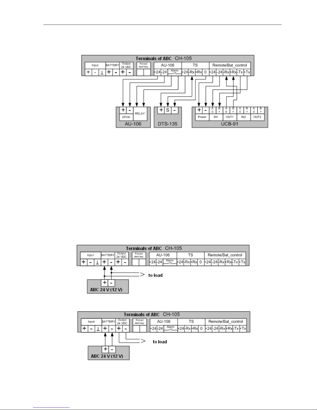
4. Connect the wires of accumulator battery and peripheral equipment to battery
charger terminals in accordance with the diagrams (refer to Paras 5.2.2 and 5.2.3).
5. This paragraph is applicable only to battery charger with marking CH-105
(Table 1). Ensure that the onboard power supply complies with the requirements of this OM
(110 or 220 VAC). From factory ABC is delivered adjusted to supply voltage from network of
220 V 50/60 Hz. If ABC receives power supply from network of 110 V 50/60 Hz, switch the
power unit to power supply from 110 V network. To switch the supply voltage of ABC to
voltage 110 V 50/60 Hz, on power unit set the voltage selector from position "220 V" to position
"110 V" (bottom-upwards). Supply voltage selector is located from the right side of power unit.
6. Connect the power cable to terminals "Input" of ABC (refer to Para. 5.2.5).
CAUTION! For safety of the personnel before connecting the power cable to ABC
make sure that it is completely de-energized.
7. Apply power to ABC with the help of key switch located on the left side of ABC
case. Five seconds after start ABC will be set to operating mode and will display present value
of AB voltage. From the factory ABC is delivered adjusted to charging current and voltage
values of 0.2 А and 25.5 V, respectively (if a battery with operating voltage below 24 V is
connected to ABC, take into consideration that because the value of charging current is small,
the battery charger will not damage the battery since the preset current is comparable with AB
leakage current; however do not leave ABC enabled for a long time without changing the
charging voltage to the appropriate value).
Note! During adjustment of ABC built-in signalling can operate. To disable the sound
signal, press the key "Mute" (refer to Figure 9).
8. In ABC menu set the value of charging current and voltage corresponding to the
connected AB (refer to Para 10).
9. Make sure that ABC operates normally: charging current and voltage do not exceed
the set values and green or yellow light-emitting diode glows (refer to functions of light-emitting
diodes, Table 6).
If the alarm operates, find and eliminate the cause of its operation (refer to the table of
alarms, Table 4).