unicraft HT 300 S User manual

HT-SERIES
HT 300 S
Operating instructions
Lift Table
HT 300 S, HT 300 M, HT 300 M PSR
HT 300 L, HT 300 L LAP, HT 600, HT 600 LAP
HT 300 M PSR HT 600
HT 300 L

2HT-Series | Version 1.01
Imprint
Product identification
Lift Table Item number
HT 300 S 6100300
HT 300 M 6100310
HT 300 M PSR 6100315
HT 300 L 6100320
HT 300 L LAP 6100325
HT 600 6100600
HT 600 LAP 6100605
Manufacturer
Stürmer Maschinen GmbH
Dr.-Robert-Pfleger-Str. 26
D-96103 Hallstadt
Fax: 0049 (0) 951 96555 - 55
E-Mail: [email protected]
Internet: www.unicraft.de
Indications regarding the operating instructions
Original instructions
Edition: 28.10.2019
Version: 1.01
Language: English
Author: SN/MS
Indications regarding the copyright
Copyright © 2019 Stürmer Maschinen GmbH, Hallstadt,
Germany.
The contents of these operating instructions are the sole
property of the company Stürmer Maschinen GmbH.
Passing on as well as copying of this document, the use
and distribution of its content are prohibited if not explic-
itly permitted. Contraventions are liable to compensa-
tion.
Subject to technical modifications and error.
Content
1 Introduction .............................................................3
1.1 Copyright............................................................3
1.2 Customer service................................................3
1.3 Limitation of liability ............................................3
2 Safety........................................................................3
2.1 Symbol explanation ............................................3
2.2 Obligations of the operating company...............4
2.3 Requirements to staff..........................................5
2.4 Personal protective equipment...........................5
2.5 Safety instructions ..............................................5
2.6 General safety regulations..................................6
2.7 Safety regulations...............................................7
2.8 Safety instructions for operating personnel........7
2.9 Safety labels on the lift table...............................8
3 Intended Use............................................................8
3.1 Residual risks .....................................................8
4 Technical Data.........................................................9
4.1 Table...................................................................9
4.2 Type plate...........................................................9
5 Transport, packaging, storage.............................10
5.1 Transport ..........................................................10
5.2 Packaging.........................................................10
5.3 Storage .............................................................10
6 Description of device............................................11
6.1 Function............................................................11
6.2 Accessories work plates (optional) ..................11
7 Assembly ...............................................................12
8 Commissioning .....................................................12
8.1 HT 300 M PSR: Disassembly and installation
of the platform swivel device............................12
9 Operation ...............................................................13
9.1 Operating conditions........................................14
9.2 Test run.............................................................14
9.3 Using ................................................................14
9.4 Load or unload lifting table...............................14
9.5 Lifting and lowering the load ............................15
9.6 Moving the lift table ..........................................16
10 Care, maintenance and repair ............................16
10.1 Care by cleaning ............................................16
10.2 Maintenance and service/repair ...................16
10.3 Servicing/repair ..............................................18
11 Checking the lift table .........................................18
12 Disposal, recycling of used devices..................18
12.1 Decommissioning...........................................18
12.2 Disposal of lubricants.....................................18
13 Troubleshooting..................................................19
14 Spare parts...........................................................19
14.1 Ordering spare parts......................................19
14.2 Spare parts drawings .....................................20
15 EU Declaration of Conformity ............................25

Introduction
HT-Series | Version 1.01 3
1Introduction
You have made a good choice by purchasing the
UNICRAFT lift table.
Read the operating manual thoroughly before commissioning
the machine.
It gives you information about the proper commission-
ing, intended use and safe and efficient operation and
maintenance of your lift table.
The operating manual is part of the lift table package.
Always keep this operating manual in the location where
your lift table is being operated. All local accident pre-
vention regulations and general safety instructions for
the operating range of your lift table must also be com-
plied with.
1.1 Copyright
The contents of these instructions are copyright. They
may be used in conjunction with the operation of the
electric chain hoist. Any application beyond those de-
scribed is not permitted without the written approval of
Stürmer GmbH.
For the protection of our products, we shall register
trademark, patent and design rights, as this is possible
in individual cases. We strongly oppose any infringe-
ment of our intellectual property.
1.2 Customer service
Please contact your dealer if you have questions con-
cerning your lift table or if you need technical advice.
They will help you with specialist information and expert
advice.
Germany:
Stürmer Maschinen GmbH
Dr.-Robert-Pfleger-Str. 26
D-96103 Hallstadt
Repair service:
Fax: 0049 (0) 951 96555-111
Email: service@stuermer-maschinen.de
Spare part orders:
Fax: 0049 (0) 951 96555-119
Email: ersatzteile@stuermer-maschinen.de
We are always interested in valuable experience and
knowledge gained from using the application-which
then could be shared and be valuable to develop our
products even further.
1.3 Limitation of liability
All information and notes in these operating instructions
were summarised while taking applicable standards
and rules, the state-of-the-art technology and our long-
term knowledge and experiences into consideration.
In the following cases the manufacturer is not liable for
damages:
- Non-observance of the operating instructions,
- Inappropriate use
- Use of untrained staff,
- Unauthorised modifications
- Technical changes,
- Use of not allowed spare parts.
The actual scope of delivery may deviate from the ex-
planations and presentations described here in case of
special models, when using additional ordering options
or due to latest technical modifications.
The obligations agreed in the delivery contract, the gen-
eral terms and conditions as well as the delivery condi-
tions of the manufacturer and the legal regulations at the
time of the conclusion of the contract are applicable.
2 Safety
This section provides an overview of all important safety
packages for the protection of operating personnel as
well as for safe and fault-free operation. Other task-
based safety notes are included in the paragraphs of
the individual phases of life.
2.1 Symbol explanation
Safety instructions
The safety notes in these operating instructions are
highlighted by symbols. The safety notes are introduced
by signal words which express the concern of the risk.
DANGER!
This combination of symbol and signal words indi-
cates an imminently dangerous situation which may
lead to death or severe injuries if they are not
avoided.

4HT-Series | Version 1.01
Safety
Tips and recommendations
It is necessary to observe the safety notes written in
these operating instructions in order to reduce the risk of
personal injuries and damages to property.
2.2 Obligations of the operating company
of the operator
The operating company is the person who operates the
lift table for business or commercial reasons by herself,
or leaves it to a third party for use or application, and
who bears the legal product responsibility for the pro-
tection of the user, the staff or for third parties.
Obligations of the operating company
If the lift table is used for commercial purposes, the op-
erating company of of the lift table must comply with the
legal working safety regulations. Therefore, the safety
notes in this operating manual, as well as the safety, ac-
cident prevention and environment protection regula-
tions applying for the area of application of of the lift ta-
ble must be met. The following applies in particular:
- The operating company must be informed about
the applying industrial safety regulations and fur-
ther analyse hazards resulting from the special
working conditions at the place of use of the lift ta-
ble. She must implement these in form of operat-
ing manuals for the operation of the lift table.
- During the entire lifetime of of the lift table, the op-
erating company must verify whether the operat-
ing manuals prepared by her correspond to the
current status of the regulations, and must adapt
these if necessary.
- The operating company must unambiguously reg-
ulate and determine the responsibilities for instal-
lation, operation, troubleshooting, maintenance
and cleaning.
- The operating company must ensure that all per-
sons who work with the lift table, have read and
understood this manual. Furthermore she must in-
struct the staff in regular intervals and inform them
about the hazards.
- The operator must provide the necessary protec-
tive equipment to the staff and order the use of the
necessary protective equipment in a binding way.
Furthermore the operating company is responsible to
keep of the lift table always in a technically flawless
state. Thus, the following applies:
- The operator must ensure that the maintenance in-
tervals described in this manual are kept.
- The operator must have all safety devices
checked regularly for their good working order
and their integrity.
WARNING!
This combination of symbol and signal words indi-
cates a possibly dangerous situation which may
lead to death or severe injuries if they are not
avoided.
CAUTION!
This combination of symbol and signal words indi-
cates a possibly dangerous situation which may
lead to minor or light injuries if they are not avoided.
ATTENTION!
This combination of symbol and signal words indi-
cates a possibly dangerous situation which may
lead to property and environmental damages if they
are not avoided.
NOTE!
This combination of symbol and signal words indi-
cates a possibly dangerous situation which may lead
to property and environmental damages if they are
not avoided.
Tips and recommendations
This symbol highlights useful tips and recommenda-
tions as well as information for an efficient and trou-
ble-free operation.

Safety
HT-Series | Version 1.01 5
2.3 Requirements to staff
Qualifications
The different tasks described in this manual represent
different requirements to the qualification of the persons
entrusted with these tasks..
Only persons reliable working procedures can be ex-
pected from, are allowed to perform all works. Persons
the responsiveness of which is affected by e. g. drugs,
alcohol or medication, are not allowed to work with the
machine.
The qualifications of the personnel for the different tasks
are mentioned below:
Operator:
The operator is instructed by the operating company
about the assigned tasks and possible risks in case of
improper behaviour. Any tasks which need to be per-
formed beyond the operation in the standard mode
must only be performed by the operator if it is indicated
in these instructions and if the operating company ex-
pressively commissioned the operator.
Qualified personnel
Due to their professional training, knowledge and expe-
rience as well as their knowledge of relevant regulations
the specialist staff is able to perform the assigned tasks
and to recognise and avoid any possible dangers them-
selves.
Manufacturer
Certain works may only be performed by specialist per-
sonnel of the manufacturer. Other personnel is not au-
thorized to perform these works. Please contact our cus-
tomer service for the execution of all arising work.
2.4 Personal protective equipment
The personal protective equipment serves to protect
persons against impairments of safety and health while
working. The staff member has to wear personal protec-
tive equipment while performing different tasks on and
with the machine which are indicated in the individual
paragraphs of these instructions.
The personal protective equipment is explained in the
following paragraph:
2.5 Safety instructions
- The lift table may only be operated at sufficiently il-
luminated workstations.
- The lift table is intended for lifting, lowering and
moving loads.
- The lift table may only be used for lifting loads on
horizontal floors.
- The lift table may only be moved when the load is
lowered.
- When lifting and lowering, the lift table must be fre-
ely positioned in the room, i.e. the positioning of
the lift table must not cause any shearing or crus-
hing edges.
- The max. load with load centre in the middle of the
lift table must not be exceeded (If the lift table is
loaded outside the load centre, the load is re-
duced to up to 33% of the maximum load).
- The maximum lifting load with load centre in the
middle of the lift table must not be exceeded.
- The lift table is not intended for moving or trans-
porting persons.
- The lift table must not be operated in potentially
explosive work areas.
- The lift table may only be used for its intended pur-
pose!
WARNING!
Danger in case of insufficient qualification
of the staff!
Insufficiently qualified persons cannot estimate the
risks while using the lift table and expose them-
selves and others to the danger of severe or lethal
injuries.
- Have all works only performed by qualified per-
sons.
- Keep insufficiently qualified persons out of the
working area.
Safety boots
The safety boots protect the feet against crushes,
falling parts and slipping over on slippery under-
ground.
Protective clothes
Protective clothes are made of a tightly fitted fabric
without the protruding parts of low tear strength.

6HT-Series | Version 1.01
Safety
Mususe
The lifting table must not be used for any improper pur-
pose! Misuse ofthe lift table is included, for example:
- Use in contravention of the regulations of the ope-
rating instructions,
- Use after unauthorized conversions or modificati-
ons,
- Exceeding the max. permissible load capacity,
- Enter the lift table,
- Transport or moving of persons with the lift table.
In case of misuse of the lift table, any warranty, liability
and other claims for damages of the operator against
the manufacturer are eliminated!
Modifications
Only use the lift table in its original condition, i.e. as sup-
plied!
The components of the lift table must not be changed in
their type and condition.
Use only spare parts (accessories) that comply with the
specifications in the spare parts list. Deviations are not
permitted!
Modifications or alterations by the operator without the
written consent of the manufacturer are prohibited and
eliminate all warranty, liability and other claims for da-
mages by the operator against the manufacturer!
2.6 General safety regulations
- During transport, storage, installation, commissioning,
operation, servicing, maintenance and troubleshoo-
ting of the lift table, compliance with the provisions of
these operating instructions must be observed.
- The lift tablee may only be operated in a safe and pro-
per condition. Its safe condition must be checked at
least once a year by qualified personnel.
- Only qualified trained persons who have been in-
structed in the handling of the lift table to carry out
work.
- Only qualified trained persons - minimum age 18
years - who are familiar with these operating instructi-
ons, in particular the safety regulations, should be au-
thorised to do the work.
- All other regulations on work safety and accident pre-
vention must be observed. The operator must issue
operating instructions.
Obligations of the staff
The following general safety regulations must be obser-
ved:
The operator is responsible for the safe use of the lift table!
- Defective or missing safety devices must be repai-
red or replaced immediately by a specialist! The
lift table must not be operated during this time!
- All activities which could endanger the safety of
man and machine must be prohibited!
- All regulations in these operating instructions must
be observed; the lift table may only be used for its
intended purpose and not improperly!
- In the case of faults, take the lift table out of opera-
tion, eliminate the cause of the fault, rectify the
fault, check the lift table for safe condition and only
then put it back into operation!
- The operator must ensure that no unauthorised
persons work on or with the lift table.
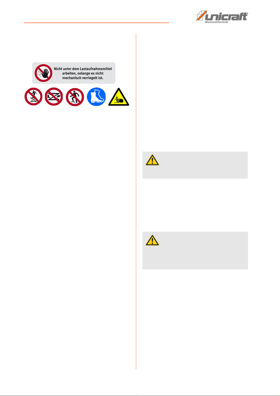
- It is not permitted to stand on load handling equip-
ment.The transport and lifting of persons is prohi-
bited.
- Set-up, modification, maintenance and inspection
work may only be carried out by trained person-
nel.
- It is noted that any unauthorised modifications and
alterations to the machine are not permitted for
safety reasons.
- In the case of hydraulic repairs to accumulator sy-
stems, the accumulator must be emptied before-
hand.
- The operating personnel must always ensure that
the maximum load capacity is not exceeded.
- Do not stand under a suspended load as loose ob-
jects can fall down at any time.
- It is forbidden to access the device if it has not
been secured by the maintenance support.

Safety
HT-Series | Version 1.01 7
2.7 Safety regulations
- The valid accident prevention regulations are to be
followed. If the lift table is intended for use by em-
ployees, it must be complied with in addition to the
relevant labor law regulations, eg. For example,
the accident prevention regulation General Regu-
lations (VBG 1).
- Before using the lift table, make sure that it is tech-
nically correct. Pay special attention to the wheels,
lifting and lowering device. Never use a damaged
lilift table. Make any repairs only by professionals.
- Never load the table with greater load or force than
the maximum load capacity.
- Pay attention to uniform load distribution!
- Never lift a load when the lift table is on an
unsuitable surface!
- Do not bring body parts (hands, fuses) under the
table when a load is lifted!
- Never try to move a load lifted from the lift table on
the table. A lifted load must never be exposed to
shock or shock loads.
- Never lift a load that can slip, or whose parts are
not firmly connected, with the lift table.
- Make sure that the operator of the lift table is al-
ways outside the range of a load that may slip or
fall off the table.
- Never leave a load lifted by the lift table unatten-
ded.
- Make sure that the ground on which the lift table
stands or where it is to be moved is sufficiently
loadable. If not, the lift table must be placed on
sufficiently solid wood or preferably metal planks
and moved there. Such a measure must be chec-
ked by an expert before lifting and moving a load.
- When using the lift table, it must be ensured that
the user can operate the lift table with the load
without any problems.
- We point out that in case of improper use no liabi-
lity for possible consequential damages can be
assumed.This also applies to the use of the lift ta-
ble that are not suitable for use, as well as any un-
authorized alteration to di esen, in particular for
the replacement of original parts with parts of
other origin.
2.8 Safety instructions for operating personnel
No operational mode which could compromise the
safety of the lift table lift platform may be undertaken.
The operator must also ensure that no unauthorised per-
sons work on the machine (e.g. also by actuating de-
vices to prevent unauthorised use).
The operator is responsible for checking the machine at
least once a day (before use) for externally visible da-
mage and defects, and for immediately reporting any
changes (including operating behaviour) that impair
safety.
The operator must ensure that the machine is always
operated in perfect condition.
If necessary, the operating personnel must be required
to wear protective clothing etc..
Safety devices must not be disassembled or put out of
operation (even here, specific reference must be made
to imminent hazards, e.g. imminent severe crushing,
loss of sight, danger to life).
If it is necessary to de-install safety devices during set-
up, repair and maintenance, the safety devices must be
re-installed immediately after completion of the main-
tenance or repair work.
ATTENTION!
Only use the lift table if you have familiarised
yourself with it or have been instructed on it. Read
the safety instructions on the lift table and in the
instructions for use carefully. The instructions must
be kept with the product for inspection.

8HT-Series | Version 1.01
Intended Use
2.9 Safety labels on the lift table
Several safety labels are attached to the lift table which
must be observed and followed (Fig. 1).
Fig. 1: Safety labels:1 Prohibition sign with reference |
2 Prohibition sign | 3 mandatory sign Wear safety shoes |
4 Warning of danger of crushing the upper limbs
The safety labels attached to the device must not be re-
moved. Damaged or missing safety markings can lead
to incorrect actions, personal injury and damage to pro-
perty. They must be replaced immediately.
If the safety markings are not recognizable and under-
standable at first glance, the device must be taken out
of operation until new safety labels have been applied.
3 Intended Use
The lift table is used exclusively for lifting, lowering and
transporting loads up to the specified maximum load, or
as a height-adjustable worktable. The permissible load
distribution and centre of gravity position must be
observed.
Transport may only take place with the load lowered.
The lift table may only be operated on firm, level
ground, in perfect condition and only by instructed
persons.
Intended use also includes compliance with all
information in these instructions. Any use beyond the
intended use or any other use is considered misuse.
Misuse:
- Lifting, moving and transporting of persons
- Operation in potentially explosive areas
Stürmer Maschinen GmbH accepts no liability for de-
sign and technical changes to the lift table.
Claims of any kind due to damage due to improper use
are excluded.
3.1 Residual risks
Consequences of non-compliance:
If the lift table is operated, serviced or repaired incor-
rectly, improperly or misused, or if it does not comply
with the safety regulations or if it is not used for its inten-
ded purpose, the following will occur
- Dangers to the health of operating personnel,
- Dangers to the lift table and objects in its area.
- The manufacturer is not liable for any damage to the
function of the lift table resulting from this.
1
34
2
DANGER!
The lift table is not explosion-proof as standard and
must not be operated in potentially explosive areas!
CAUTION!
lease notice that every machine has residual risks.
Great care must be taken when carrying out all ope-
rations (even the simplest ones). Safe working
depends on you!

Technical Data
HT-Series | Version 1.01 9
4 Technical Data
4.1 Table
Required space, load capacity and condition of the substrate:
4.2 Type plate
Fig. 2: Type plate of the lift table HT 300 S
Type HT 300 S HT 300 M HT 300 M
PSR
HT 300 L HT 300 L
LAP
HT 600 HT 600
LAP
Length (product) approx. [mm] 970 1200 1200 1900 2000 1900 2000
Width/Depth (product) approx.
[mm]
590 740 740 740 1000 740 1000
Height (product) approx. [mm] 400 400 400 400 430 400 430
Weight (net) approx. [kg] 60 80 80 140 188 190 238
Load capacity [kg] 300 300 300 300 300 600 600
Table height min. [mm] 400 400 400 400 430 400 430
Table height max. [mm] 1010 1010 1010 1010 1040 1010 1040
Roll diameter [mm] 125 125 125 125 125 125 125
Max. plate weight for swivel
frame [kg]
120
Length swivel frame [mm] 1800
Width swivel frame [mm] 1500
Type HT 300 S HT 300 M HT 300 M
PSR
HT 300 L HT 300 L
LAP
HT 600 HT 600 LAP
Required
space
(BxWxT) [mm]
1000 x 400
x 610
with work
table
1200 x 400
x740
without
work table
1200 x 400
x 740
without
platform
swivel unit
1010 x 420
x 2010
with work
table
1010 x 420
x 2010
with work
table
1010 x 420
x 2010
with work
table
1010 x 420
x 2010
with work
table
Load capacity Concrete classification B15
Condition flat, even, non-slip, incline-free
60 kg

10 HT-Series | Version 1.01
Transport, packaging, storage
5 Transport, packaging, storage
5.1 Transport
Check the lift table on delivery for any visible transporta-
tion damage. If you notice any damage to the device
please report this immediately to the carrier or dealer.
Unloading the lift table
Only trained unloading personnel may be used for the
following work!
Unloading with a forklift
Move the forks to the centre of the intended positions on
the pallet of the lift table and lift carefully. Carefully lift
the lift table from the truck, note the weight of the lift ta-
ble!
Transport
Transport to the installation site by forklift truck or pallet
truck in accordance with the general safety regulations.
Unpacking
Lift the lift table from the transport pallet using a forklift
forklift. Move the forks centrally under the long side of
the lift table and lift carefully. Carefully lift the lift table off
the transport pallet. Note the weight of the lift table! Re-
move the transport pallet and place the lift table on the
ground.
5.2 Packaging
All used packaging materials and packaging aids are
recyclable and should be taken to a materials recycling
depot to be disposed of.
The delivery packaging is made of cardboard, so
please dispose carefully by having it chopped up and
given to the recycling collection.
The film is made of polyethylene (PE) and the cushioned
parts of polystyrene (PS). These materials should be
taken to a collection point for recyclable materials or to
the local waste disposal company.
5.3 Storage
Short-term storage
- dry
- protect the lift tables from corrosion
- in a stable place.
Oil the lift table and store it in a frost-free and dry env-
ironment.
Long-term storage
- dry
- protect the lift tables from corrosion
- protect the lift tables from contaminants
- in a stable place.
Store the lift table only with the scissor lift lowered and
the drain valve closed. Do not place anything on the lift
table.
NOTE!
Protect the lift tablefrom moisture.
WARNING!
Danger of injury when unloading or transporting the
lift table The weight of the lift table may cause it to
fall!
- Only use approved, tested hoists and load hand-
ling attachments with a load capacity of at least
1000 kg.
- Do not stand under the load when lifting and setting
down! Direct persons standing nearby out of the
danger area.
- Only transport the lifting table on level, firm ground!
- Wear safety boots with steel caps!

Description of device
HT-Series | Version 1.01 11
6 Description of device
Illustrations in these operating instructions are for basic under-
standing only and may differ from the actual version.
Fig. 3: Description of devices HT 300 S and HT 300 M (top),
HT 300 M PSR (center), HT 300 L (bottom)
Fig. 4: Description of the lift table HT 600
6.1 Function
The height adjustment of the lifting table is based on the
scissor principle. By actuating the foot pedal down-
wards, the scissors are moved by hydraulic force and
the lift table platform moves upwards. When the foot le-
ver is released, the lift table movement comes to a
standstill and the lift table platform remains in this posi-
tion. By lifting the foot lever, the lift table platform is lo-
wered for the duration of the operation.
The hydraulic power is transmitted via the foot pump to
the hydraulic cylinder. Foot pump and hydraulic cylin-
der are a fixed unit.
HT 300 M PSR
- Provides one person with easy loading of panels
onto the platform frame and pivoting from vertical
to horizontal position
- Swivel frame with two layer locking in vertical and
horizontal position
6.2 Accessories work plates (optional)
HT 300 S
- Smooth metal work plate, 1000 x 600 mm
- Beech multiplex work plate, 1250 x 800 mm
- Beech multiplex hole grid work plate, 1250 x 800
mm
HT 300 M
- Beech multiplex hole grid work plate,
1600 x 790 mm
HT 300 M PSR
- with swivelling frame (scope of delivery)
Platform of the
lift table
Scissors
Maintenance
support
Guide roll
Foot
pedal
Hydraulic
cylinder
Guide roll
All side
rollers
Fixing
swivel-
ling frame
Assembly
frame
Locking
swivelling
frame
Lift Table
Swivelling
frame
Counterweight
Platform of the
lift table
Foot
pedal
Guide roll
Hydraulic
cylinder
Scissors
Platform of the lift table
with different accessories
(optional)
Maintenance
support
Foot
pedal
Hydraulic
cylinder
Scissors
Guide
roll

12 HT-Series | Version 1.01
Assembly
HT 300 L
- Different work plates can be mounted on the base
frame
HT 300 L LAP
- Beech multiplex hole grid work plate,
2000 x 1000 x 30 mm (scope of delivery)
HT 600
- Different work plates can be mounted on the base
frame
HT 600 LAP
- Beech multiplex hole grid work plate,
2000 x 1000 x 30 mm (scope of delivery)
7 Assembly
The lift table is delivered ready assembled.
8 Commissioning
All work on commissioning the lift table may only be car-
ried out by qualified personnel.
All functions othe lift table must be checked before com-
missioning.
The lift table must be stable and set up in such a way
that no crushing or shearing points occur between the
lift table or the load and parts of the environment. During
normal operation, it must be possible to carry out activi-
ties on the lift table or load without difficulty.
The following installation and operating conditions must
be observed:
- The integrationof the lift table into the existing ma-
chinery must be carried out in such a way that the
basic safety requirements of the EC Machinery Di-
rective 2006/42/EC are observed (must be chec-
ked by the operator of the lift table).
- the environment must not be potentially explosive
- These operating instructions and any other asso-
ciated operating instructions must be read and un-
derstood.
8.1 HT 300 M PSR: Disassembly and installa-
tion of the platform swivel device
The following steps must be followed to disassemble the
platform swivel device from the lifting table:
Step 1: Loosen the screws to fix the swivel frame (Fig. 5,
arrow) on both sides of the swivel frame and
slide the fixing plates backwards so that the
bolts of the swivel frame are free at the top.
Fig. 5: Disassembly of the platform swivel device
Step 2: Lift the swivel frame upwards out of the bearing
and remove it from the front (Fig. 5 below).
Step 3: Move the swivel frame to the side.
CAUTION!
The operator must take into account the weight of
the individual parts (approx. 25 kg each).
The work sequence must be strictly adhered to.
Use protective gloves!
Wear safety boots!

Operation
HT-Series | Version 1.01 13
Fig. 6: Disassembly of the swivel device
Step 4: Slightly loosen the fastening screws of the swivel
device at the front and rear of the lifting table,
swivel the swivel device upwards and pull it
upwards out of the fastening screws.
Step 3: Move the swivel device to the side.
Now the lift table with the suitable platform can be used
as a lift table.
The platform swivel device is reassembled in the re-
verse sequence to the disassembly described above.
9 Operation
CAUTION!
Before operating the lift table, the operator must
ensure that there is no danger from the movement of
the lift platform.
DANGER!
DANGER TO LIFE DUE TO FALLING OF THE
LOAD!
Falling loads can cause serious injury or death. .
- Never exceed the specified maximum load.
- Never move the lifted load.
- Never work under the lifted load.
- Observe the load manufacturer's instructions on
the load application point.
- Distribute the weight centrally on the table of the lift
table
- Only lift loads with the lift table on a horizontal, level
and firm surface.
- Do not lift any persons individually or together with
the load.
- When leaving the workplace, lower the load if it is
not additionally mechanically secured.
Use protective gloves!
Wear safety boots!
Wear protective clothes!

14 HT-Series | Version 1.01
Operation
9.1 Operating conditions
The working area must be dry, fire and explosion pro-
tected and free of corrosive and toxic substances.
The working area must be adequately illuminated.
Dangerous goods such as flammable, toxic or radioac-
tive materials must not be lifted with the lift table.
9.2 Test run
Before operation under load, carry out a test with testing
of all functions without load.
9.3 Using
The lift table can be used for all work which corresponds
to the intended use in the chapter of the same name. It
can therefore be used as work equipment for lifting and
lowering loads, as well as a height-adjustable assembly
table.
The lift table must not be used for work if this does not
correspond to the intended use of the lift table.
In order to protect the wheels and chassis of the lift ta-
ble, no large uneven surfaces (potholes, thresholds,
etc.) should be driven over.
9.4 Load or unload lifting table
When loading or unloading the lift table, the permissible
load balancing must be observed and followed. The
load applied to the lift table must be secured against fal-
ling by suitable equipments. However, it is usually not
necessary to secure the load. It is only necessary for
loads that have an unstable position on the lift platform
(e.g. rolling elements).
Load balancing
The nominal load of the lift table is based on a load
evenly distributed on the platform. If this nominal load is
not evenly distributed on the platform, the nominal load
must be reduced as shown in the figures below.
Evenly distributed:
The load is distributed over the complete platform.
100% of the nominal load is permitted.
Fig. 7: Evenly distributed
Unevenly distributed in transverse direction:
The load is distributed over half of the platform (trans-
verse direction). 50% of the nominal load is permitted.
Fig. 8: Unevenly distributed in transverse direction
NOTE!
- The operating personnel must be familiar with the
operation and functions as well as the safety regu-
lations when operating the lift table.
- The operator must provide the necessary instruc-
tion for the operating personnel.
NOTE!
Check that no component is rusted, damaged or
broken. A lift table with one or more of these cha-
racteristics must not be used.
Without any load on the table, check that the foot
pedal for the hydraulic pump can be moved freely
and smoothly and does not jam at any point in the
adjustment range.

Operation
HT-Series | Version 1.01 15
Unevenly distributed longitudinal direction:
The load is distributed over half of the platform (longitu-
dinal direction). 33% of the nominal load is permitted.
Fig. 9: Unevenly distributed longitudinal direction
9.5 Lifting and lowering the load
Lifting
Before the lift table platform is raised, the lift table must
first be fixed in place by the rollers.
By repeatedly pressing the lever (Fig. 10), the platform
moves upwards. Lock the brakes before lifting and lo-
wering loads.
Fig. 10: Lifting the lift table: HT 300 (top), HT 300 L (bottom)
Fig. 10: Lifting the lift table: HT 600
Make sure that you do not place any body parts (hands,
legs, etc.) under the table when the load is lifted. There
is a high risk of injury!
Lowering
The same requirements that applied in the previous
chapter apply here.
By lifting the lever (Fig. 11) the platform moves down-
wards (HT 300 S, M, M PSR, HT 600).
Fig. 11: Lowering the lift table: HT 300 S, M, M PSR (top),
HT 600 (bottom)

16 HT-Series | Version 1.01
Care, maintenance and repair
Modell HT 300 L:
When the lever (Fig. 12) is actuated, the platform moves
downwards (HT 300 S, M, M PSR, HT 600).
Fig. 12: Lowering the lift table: HT 300 L
Lifting and lowering the load can be interrupted at any
stage of the operation. The load is held securely in its
current position.
Never work under the lifted load!
When leaving the workplace, lower the load if it is not se-
cured mechanically!
9.6 Moving the lift table
Before the lift table is moved, the load must always be
lowered completely. Furthermore, the load must be se-
cured against slipping and falling before the lift table is
moved.
10 Care, maintenance and repair
10.1 Care by cleaning
The lift table must always be kept in a clean condition.
All plastic and lacquered surfaces should be cleaned
using a soft, damp cloth and a neutral cleaning agent.
Remove any excess lubricant or leaked oil using a dry,
lint-free cloth.
10.2 Maintenance and service/repair
If maintenance or repair work has been carried out on
the lift table, a function test must then be carried out.
- It is forbidden to reach into the lift if it is not secu-
red by the maintenance support.
- Wear suitable protective clothing
- wear safety shoes
Maintenance and repair work may only be carried out by
competent, trained and instructed personnel. Energy
supply systems must be interrupted. If necessary,
further operating instructions must be observed.
Secure the lift table with the maintenance supports:
- Remove load from the lift table
- Folding down the maintenance supports of the lift
table
- Lower the lift table, until the maintenance supports
block the further lowering.
CAUTION!
Risk of crushing!
When the load is lowered, the upper and lower limbs
may be crushed.
- Do not hold the upper and lower limbs between the
load and the ground when the load is lowered.
NOTE!
The operator must have sufficient freedom of move-
ment.
Use protective gloves!
NOTE!
Never use strong cleaning agents for any cleaning
work. This can lead to damage or destroy the device.
ATTENTION!
The mechanical and general condition of the lift
table must be checked by a specialist workshop at
least every 12 months.

Care, maintenance and repair
HT-Series | Version 1.01 17
Daily maintenance:
- Check all components for damage and have them
replaced by qualified personnel if necessary..
Monthly maintenance::
- Slightly lubricate the rollers and bearings.
Yearly maintenance:
- Carry out and document lift table inspection in ac-
cordance with regulations.
- Models HT 600 and HT 600 LAP:
Change hydraulic oil
Move the platform slightly upwards to fold in the main-
tenance supports.
If maintenance or repair work has been carried out on
the lift table, a function check must then be carried out.
- It is forbidden to access the lift table if it is not se-
cured by the safety support.
- Wear suitable protective clothing.
- Wear safety shoes
- Before working on the hydraulic system, depres-
surise it by lowering the lifting table onto the safety
supports.
If the lift table is used very frequently or regularly under
"difficult operating conditions" (e.g. in particularly dusty
environments, under the influence of chemicals or
vapours, etc.), the inspection should be carried out at
shorter intervals.
If you have any questions about the condition of the lift
table, please contact a specialist workshop.
If the lift table does not function properly, contact a spe-
cialist dealer or our customer service. Contact details
can be found in chapter 1.2 Customer service.
All protective and safety devices must be reinstalled im-
mediately after completion of repair and maintenance
work.
Step 1: Lubricate all moving parts of the lift table with
high quality grease.
Step 2: Check the lift table for external damage before
each use.
Step 3: Models HT 600 and HT 600 LAP: Check the hy-
draulic oil level at regular intervals.
Step 4: Make sure that all safety notices on the lift table
are clearly legible.
Check oil level (only models HT 600 and HT 600 LAP ) /
Oil changes
Step 1: Lower the lift table and open the cap on the
pump tank filler neck.
For oil change: Drain used oil.
Step 2: Top up oil (HLP 32) if necessary or when
changing oil. Oil tank volume: 1 litre.
Oil quantity in the hydraulic cylinder:
max. 0.66 litres.
Step 3: Close the filler neck and lift and lower the lift
table several times. Check the oil level again
and screw in the screw plug again.
Step 4: Bleed the hydraulic system (see "Venting").
Venting (only Models HT 600 and HT 600 LAP)
After some time, or after filling with oil, air bubbles may
form in the hydraulic system of the lift table and affect its
function.
Step 1: Lower the lift table to min. height
Step 2: Slowly and carefully open the oil filler plug to
allow the trapped air to escape.
Step 3: Check the lift table for proper function, repeat if
necessary.
Oil, grease and cleaning agents are ha-
zardous to the environment and must not
be added to waste water or normal
household waste. Dispose of these
agents in an environmentally friendly
manner.
NOTE!
The hydraulic cylinders (with integrated pump) of the
HT 300 series (HT 300 S, HT 300 M and HT 300 L) are
maintenance-free. If an oil leak occurs, the cylinder
must be replaced.
NOTE!
HT 600 and HT 600 LAP: The oil level must be chec-
ked by a specialist workshop or specialist at least
once a year.
WARNUNG!
The cleaning cloths soaked in oil, grease or cleaning
agents are easily combustible. Collect the rags or
the cleaning wool in a suitable, closed container and
dispose of them in an environmentally friendly man-
ner - do not dispose of them with your household
waste!

18 HT-Series | Version 1.01
Checking the lift table
10.3 Servicing/repair
Infolge von Verschleiß kann es vorkommen, dass an As
a result of wear and tear, maintenance work may have to
be carried out on the lift table.
11 Checking the lift table
The lift table must be checked by a qualified person to
ensure that it is in a safe working condition, in accor-
dance with the provisions of the German Industrial
Safety Regulations and the BGR 500, Chapter 2.10, Pa-
ragraph 2.9, before commissioning and as required at
intervals of no more than 1 year. A person can be regar-
ded as qualified if he / she has at least the qualification
that was previously provided to the expert. The scope of
the test and the inspection deadlines are governed i.a.
according to the results of the risk assessment to be
carried out. Check intervals, the operator can assume
that these measures are sufficient. Type, extent and
deadlines of the tests described in the BGR 500 are pre-
vious practice and comply with the rules of technology.
The test is essentially a visual and functional test. It
covers the examination of the condition of the compo-
nents and equipment, the completeness and effective-
ness of the safety equipment and the completeness of
the test book. If a test period of no more than one year is
adhered to, the operator can assume that this period is
adequate. Verification of scissor lift tables must be veri-
fied by a log book.
12 Disposal, recycling of used devices
Please take care in your own interest and in the interest of
the environment that all component parts of the machine
are only disposed of in the intended and permitted way.
12.1 Decommissioning
Immediately decommission used machines in order to
avoid later misuse and endangering of the environment
or of persons.
Step 1: Eliminate all environmentally hazardous operat-
ing materials from the used device.
Step 2: If required, disassemble the machine into easy-
to-handle and usable components and parts.
Step 3: Dispose of machine components and operating
materials by the disposal channels provided.
12.2 Disposal of lubricants
Remove any leaking, used or excessive grease at the lu-
bricating points.
Disposal notes for used lubricants are available from the
manufacturer of the lubricants. If necessary, request the
product-specific data sheets.
NOTE!
Servicing work may only be carried out by qualified
personnel with mechanical knowledge!

Troubleshooting
HT-Series | Version 1.01 19
13 Troubleshooting
14 Spare parts
14.1 Ordering spare parts
The spare parts may be purchased with the authorised
dealer or directly with the manufacturer. Please find the
corresponding contact data in Chapter 1.2 Customer
service.
Indicate the following basic information for requests or
orders of spare parts:
- Type of device
- Item No.
- Position No.
- Year of construction:
- Quantity
- Required mode of dispatch (mail, freight, sea, air,
express)
- Address of dispatch
Spare part orders which do not include the above indi-
cations may not be taken into consideration. If the indi-
cations regarding the mode of dispatch are missing, the
product is dispatched at the discretion of the supplier.
You will find information regarding the device type, item
No. and year of construction on the type plate which is
fixed on the lift table.
Example
The guide roll for the lift table HT 300 S bestellt werden.
The guide roll have the position number 13 in the spare
parts Drawing.
When ordering spare parts, send a copy of the spare
parts drawing with the marked component (guide roll)
and marked item number 13 to the authorised dealer or
to the spare parts department and provide the following
information:
- Type of device: Lift Table HT 300 S
- Artikelnummer: 6100300
- Position number: 13
In case of service, the following drawing shall help to
identify the necessary spare parts.
Faults Possible cause Solution
The lift table does not lower comple-
tely
Maintenance support not folded in Slightly raise the lift table, fold in the
maintenance support.
Clamped part in the lift table scis-
sors
Slightly raise the lift table, remove
part.
The lift table cannot be raised The lift table overloaded Reduce the load
Defective pump Replace the pump
DANGER!
Risk of injury due to the use
of wrong spare parts!
Dangers may result for the user and damages as
well as malfunctions may be caused by using wrong
or damaged spare parts.
- Only use original spare parts of the manufacturer or
spare parts admitted by the manufacturer.
- Always contact the manufacturer in case of uncer-
tainties.
Tips and recommendations
The manufacturer's warranty will become null and
void if non-permissible spare parts are being used

20 HT-Series | Version 1.01
Spare parts
14.2 Spare parts drawings
Fig. 13: Spare parts drawing HT 300 S
HT 300 S
Pos. Item number Description Pos. Item number Description
1 19 001 001 02 Sticker 5.5 ISO 4014 - M16 x110 Hex bolt
2 19 001 009 00 Cylinder holder 5.6 ISO 4014 - M16 x 65 Hex bolt
3 19 001 011 00-AA Base frame 6 19 001 041 00-AA Support frame
4 19 001 020 00-AA Scissors small cpl 7 19 001 051 00-AA Pressure fork
4.1 19 001 021 00-AA Scissors small 8 19 001 060 00 Foot bar
4.2 19 001 022 00-AA Locking lever 8.1 19 001 060 02 Foot bar
4.3 DIN 125 - A17 Washer 8.2 19 001 060 03 Fastening
4.4 DIN 625 T1 - 6203 - 2RS Deep groove ball
bearing
8.3 DIN 913 - MS x 20 Threaded pin
4.5 ISO 10511 - M16 Hex nut 8.4 ISO 4032 - MS Hex nut
4.6 ISO 4014 - M16 x 65 Hex bolt 8.5 ISO 4762- MS x 45 Allen® screw
4.7 ISO 4017 - M16 x 45 Hex bolt 9 ISO 4017 - M12 x 30 Hex nut
5 19 001 030 00-AA Scissors large cpl 10 ISO 401 7 - MS x 10 Hex nut
5.1 19 001 031 00-AA Scissors large 11 ISO 4762- MS x12 Allen® screw
5.2 DIN 125 - A17 Washer 12 Power Packer
DSC0101-12-S2
Medipack
5.3 DIN 625 T1 - 6203 - 2RS Deep groove ball
bearing
13 Torwegge
L-IL-PUZK-125-K-3
Guide roll
5.4 ISO 10511 - M16 Hex nut 14 Torwegge L-IL-PUZK-
125-K-3-DSN
Guide roll with
brake
This manual suits for next models
13
Table of contents
Other unicraft Lifting System manuals
Popular Lifting System manuals by other brands

PLATFORM BASKET
PLATFORM BASKET RR 14 EVO 2-400 Hybrid Use and maintenance manual

Bear
Bear 30-41204 Installation and service manual

APlusLift
APlusLift HW-10KBP Installation manual & operation instructions

Vestil
Vestil CART-600-S-HR instruction manual

Liko
Liko Solo SupportVest Instruction guide

Consul
Consul Prolift 2.30 EL Operating & installation instructions