Unilift 542KB User manual

4590010 03/06
EQUIPMENT USE AND SAFETY
Safe Setup And Use Of The 542KB UniLift
Please review the following setup and use instructions before operating the 542KB UniLift.
1. Make sure the 542KB UniLift has been safely set up away from power lines (maintain at least 10 feet
of clearance).
2. Disconnect the 542KB UniLift from the transporting vehicle before setup. If the unit is parked on a
slope, chock the wheels or set the outriggers first, to prevent rolling.
3. Extend and set up the outriggers (setup instructions are located at each outrigger). Make sure the
outriggers are set on solid footing. The green light on the lower control panel indicates that the
outriggers are properly set. NOTE: If the green indicator light is lit before all four outriggers are set,
the unit is not safe to operate.
4. If the 542KB UniLift is set on a slope (5° maximum), the outriggers MUST be used for leveling.
5. Make sure all electrical power cords are safely stored to prevent tangling or crushing.
6. Always wear the proper body harness, and keep the harness secured to the lanyard ring whenever
operating the 542KB UniLift from the bucket.
7. DO NOT exceed the manufacturer's rated lifting capacities.
8. The lower controls are for emergency use only, when a worker is present in the bucket.
9. It is PROHIBITED and DANGEROUS to use railings, planks, ladders, or other devices in the bucket
to achieve additional working height or reach.
10. Watch for overhead obstructions when booming up.
11. Keep observers and other workers out of the work area.
12. DO NOT lift materials with the lanyard ring while operating the 542KB UniLift from the bucket.
13. When using the 542KB UniLift as a crane, DO NOT stand under the load.
14. Make sure the boom and outriggers are properly stowed, and the bucket is securely locked in place
before transporting the 542KB UniLift.
15. DO NOT operate the 542KB UniLift if it is in need of repairs.
16. Be sure to read and thoroughly understand the Operation Section in the Operators Manual.
Courtesy of Crane.Market

4590010 03/06
OPERATOR SAFETY
Training Checklist For The 542KB UniLift
Please review the Checklist items. Initial each item then sign and date this Checklist below.
The ONLY person permitted to operate the 542KB UniLift shall be the person who has
received instructions prior to rental.
I have received instructions and understand the operation and proper use of the 542KB
UniLift controls. I agree to use the 542KB UniLift in a manner consistent with its intended
application.
I have received instructions and understand the use of the outriggers to set up and level the
542KB UniLift.
I understand that the maximum bucket capacity of the 542KB UniLift is 300 lbs.
I have received instructions and understand the use of the Emergency Manual Lowering
Valve and other emergency procedures.
I will not attempt to alter or disable any safety devices, guards, or interlocks.
I have been shown the location of the Operators Manual, and was instructed to read the
manual prior to operation.
I understand that the 542KB UniLift is NOT INSULATED and shall not be used within
10 feet of any power lines.
I will wear the body harness, with the 4 ft. lanyard attached, at all times when operating the
542KB UniLift from the bucket.
I have received instructions and understand the procedures for stowing the boom and
outriggers, and locking the bucket in place before transporting the 542KB UniLift.
Before transporting the 542KB UniLift, I will verify that the tongue is securely attached
and locked to a 2-inch hitch ball, safety chains are in place, and the trailer lights are
operable.
Signed: Date:
Courtesy of Crane.Market

4520362-1/0606
TABLE OF CONTENTS
Subject Page
DESCRIPTION . . . . . . . . . . . . . . . . . . . . . . . . . . . . . . . . . . . . . . . . . . . . . . . . . . . . . . . . . . . . . . . . . . . . . . i-1
SPECIFICATIONS . . . . . . . . . . . . . . . . . . . . . . . . . . . . . . . . . . . . . . . . . . . . . . . . . . . . . . . . . . . . . . . . . . . ii-1
OPERATION . . . . . . . . . . . . . . . . . . . . . . . . . . . . . . . . . . . . . . . . . . . . . . . . . . . . . . . . . . . . . . . . . . . . . . . . 1-1
Transporting .. . . . . . . . . . . . . . . . . . . . . . . . . . . . . . . . . . . . . . . . . . . . . . . . . . . . . . . . . . . . . 1-1
Parking . . . . . . . . . . . . . . . . . . . . . . . . . . . . . . . . . . . . . . . . . . . . . . . . . . . . . . . . . . . . . . . . . . 1-1
Setting The Outriggers . . . . . . . . . . . . . . . . . . . . . . . . . . . . . . . . . . . . . . . . . . . . . . . . . . . . . 1-2
Controls (Thru S/N: 42059) . . . . . . . . . . . . . . . . . . . . . . . . . . . . . . . . . . . . . . . . . . . . . . . . . . 1-4
Controls (S/N: 42060 & Above) .. . . . . . . . . . . . . . . . . . . . . . . . . . . . . . . . . . . . . . . . . . . . . . 1-5A
Pre-Start Inspection .. . . . . . . . . . . . . . . . . . . . . . . . . . . . . . . . . . . . . . . . . . . . . . . . . . . . . . . 1-6
Bucket Lock. . . . . . . . . . . . . . . . . . . . . . . . . . . . . . . . . . . . . . . . . . . . . . . . . . . . . . . . . . . . . . 1-6
Bucket Operation. . . . . . . . . . . . . . . . . . . . . . . . . . . . . . . . . . . . . . . . . . . . . . . . . . . . . . . . . . 1-6
Crane Operation. . . . . . . . . . . . . . . . . . . . . . . . . . . . . . . . . . . . . . . . . . . . . . . . . . . . . . . . . . . 1-7
Shutdown . . . . . . . . . . . . . . . . . . . . . . . . . . . . . . . . . . . . . . . . . . . . . . . . . . . . . . . . . . . . . . . . 1-7
System Recharging. . . . . . . . . . . . . . . . . . . . . . . . . . . . . . . . . . . . . . . . . . . . . . . . . . . . . . . . 1-8
Emergency Controls.. . . . . . . . . . . . . . . . . . . . . . . . . . . . . . . . . . . . . . . . . . . . . . . . . . . . . . . 1-8
EMERGENCY PROCEDURES. . . . . . . . . . . . . . . . . . . . . . . . . . . . . . . . . . . . . . . . . . . . . . . . . . . . . . . . . . 2-1
Platform Control Station Switch Failure.. . . . . . . . . . . . . . . . . . . . . . . . . . . . . . . . . . . . . . . 2-1
Lower Control Station Switch Failure.. . . . . . . . . . . . . . . . . . . . . . . . . . . . . . . . . . . . . . . . . 2-1
Emergency Stop Switches (S/N: 42060 & Above) .. . . . . . . . . . . . . . . . . . . . . . . . . . . . . . . 2-1
Hydraulic Line Failure. . . . . . . . . . . . . . . . . . . . . . . . . . . . . . . . . . . . . . . . . . . . . . . . . . . . . . 2-1
Bucket Operator Disabled. . . . . . . . . . . . . . . . . . . . . . . . . . . . . . . . . . . . . . . . . . . . . . . . . . . 2-1
Power Failure. . . . . . . . . . . . . . . . . . . . . . . . . . . . . . . . . . . . . . . . . . . . . . . . . . . . . . . . . . . . . 2-1
Booster Cable Instructions. . . . . . . . . . . . . . . . . . . . . . . . . . . . . . . . . . . . . . . . . . . . . . . . . . 2-2
. . . . . . . . . . . . . . . . . . . . . . . . . . . . . . . . . . . . . . . . . . . . . . . . . . . . . . . . . . . . . . . . . . . . . .
Courtesy of Crane.Market

4520362-1/0606
Page i - 1
DESCRIPTION
The UniLift Model 542 KB Universal Crane and Personnel Lift functions as both a personnel carrier and crane, in one unit.
A single operator can use the UniLift as a personnel carrier or a universal crane with minimal conversion time. The unit is also
light enough to be rolled by one person.
The UniLift Model 542 KB consists of the following basic components:
Figure i-1.
Self-Leveling UniLift With Personnel Bucket Attached
ADJUSTABLE OUTRIGGERS
Outriggers are used for absorption of tipping load during use, and are manually set. Adjustable up to three feet, the outriggers
assure that the unit can be leveled and rests firmly on solid footing. Electrical interlocks prevent lift/crane operation until all
four outriggers are fully extended and resting firmly on the ground. A green light is located on the base control station, and
indicates that all outriggers are set up on solid footing.
Courtesy of Crane.Market

4520362-1/0606
Page i - 2 - Description
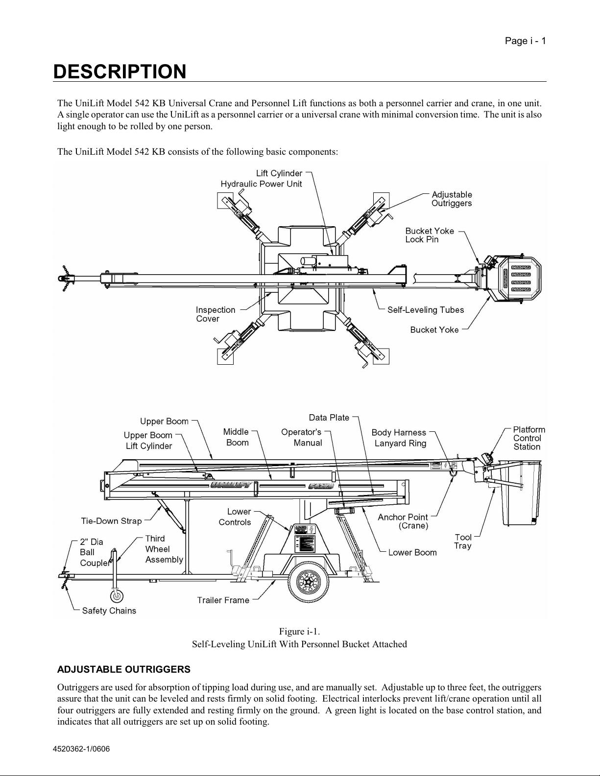
SINGLE AXLE TRAILER FRAME WITH 2" (50.8 mm) BALL COUPLER WITH SURGE BRAKES, AND
THIRD WHEEL
A torsion bar type of axle, rated at 3500 pounds (1589 kg), is used for road stability while towing. The 2" (50.8 mm) diameter
ball coupler with surge brakes, and third wheel assembly are provided as standard equipment, allowing the unit to be transported
to a job site and unhitched. WARNING: DO NOT ATTEMPT TO TOW THIS LIFT WITH A MULTI-PIECE HITCH
BALL OR A HITCH BALL OTHER THAN 2" (50.8 mm). Safety chains are also provided and shall always be attached when
the unit is to be transported. Tire size is P205/75R14 with a max load rating of 1532 Lbs. (696 kg) at 35 psi (241 kPa).
PLATFORM AND LOWER CONTROLS
Full controls are provided at both the bucket and the base. The DOWN OVERRIDE-OFF-ENABLE switch (Platform Control
Station), and the PLATFORM CONTROL/LOWER CONTROL switch (Lower Control Station) are used to enable each station.
A key switch is provided at the Lower Control Station for security. Emergency lowering controls are also provided at the end of
the upper boom, and inside the base assembly.
POWER REQUIREMENTS AND CHARGING CAPABILITIES
The unit is powered by two, 6-VDC deep-cycle batteries connected in series, yielding 12 VDC for approximately eight hours of
operation under typical use. A built-in 12-VDC, 30-amp battery charger is provided to restore charge to the batteries, and is
equipped with automatic cutoff when full charge is reached. The battery cutout relay also permits operation while the unit is
plugged in and the batteries are recharging. (See the section on Inspection and Maintenance for more details on battery system.)
HYDRAULIC LIFT CYLINDERS
Aerial lift is provided by two 3-1/2 inch (88.9 mm), double-acting cylinders: the lower lift cylinder is attached to the lower and
middle booms. The upper lift cylinder is attached to the upper and middle booms. Hydraulic power is provided by a 12-VDC
hydraulic system, connected to the lower lift cylinder.
SURGE BRAKES
Hydraulic brakes are standard equipment. They are surge activated and use a standard 2-inch (50.8 mm) diameter ball coupler.
Breakaway chains are provided for emergency stopping.
OVER-CENTER SAFETY SWITCH
An over-center safety switch is mounted to the upper boom. This switch continuously monitors the angle of the upper boom, and
prevents it from going into an over-center position.
PERSONNEL BUCKET
The fiberglass personnel bucket is self-leveled by the linkage which is connected to the boom structure. Older models were gravity
leveled and hydraulically dampened with a positive work-position locking handle. The bucket is made removable for crane
operation if required. Travel limits prevent continuous rotation of the booms and bucket. A body harness is provided with each
unit and shall be worn at all times when operating unit from the bucket.
LEVELING SAFETY SWITCH (OPTION)
The leveling safety switch continuously monitors the trailer for an unsafe tilt condition (exceeding 5°) during set-up and operation.
The green Trailer Level Indicator Light is lit when the trailer tilt is within the 5° range. If the tilt exceeds the limit during set-up,
the controls will not operate. If an unsafe condition occurs during operation, only the boom DOWN functions will work.
110-VAC ACCESSORY POWER OUTLET (OPTION)
A 110-VAC outlet, 15 amps maximum capacity, is available at the bucket to power accessory tools.
Courtesy of Crane.Market

4520362-1/0606
WARNING: NEVER LIFT OVER SPECIFIED WEIGHT OR TIPPING CAN OCCUR, CAUSING
SERIOUS INJURY OR DEATH TO OPERATOR.
DANGER
ELECTROCUTION HAZARD, STAY AT LEAST 10 FEET (3 m) FROM POWER LINES. THIS UNIT IS NOT
INSULATED FROM ELECTRIC SHOCK. DEATH OR SERIOUS INJURY TO OPERATORS AND/OR
BYSTANDERS CAN RESULT FROM CONTACT WITH ELECTRICAL WIRES.
Description - Page i - 3
UNIVERSAL CRANE
An anchor point is provided on the upper boom for lifting loads up to 300 pounds (136 kg) with the personnel bucket removed.
(See Figure i-2)
Figure i-2
Personnel Lift/Crane Work Area
Courtesy of Crane.Market

4520362-1/0310
Page ii - 1
SPECIFICATIONS
GENERAL Personnel Bucket Crane
Working Height 42'-0" (12.80 m) 36'-0" (11.00 m) *
Platform Height 36'-0" (11.00 m) ------
Platform Reach from Center of Rotation 22.6' (6.8 m) 18' (5.5 m)
Stowed Travel Height 7'-10" (2.39 m) 7'-10" (2.39 m)
Stowed Travel Width 7'-6" (2.29 m) 7'-6" (2.29 m)
7'-3" (2.22 m)† 7'-3" (2.22 m) †
Stowed Travel Length 25'-6" (7.8 m) 25'-6" (7.8 m)
Rated Load Capacity 300 lbs. (136 kg) 300 lbs. (136 kg)
Shipping Weight 2900 lbs. (1315 kg) 2900 lbs. (1315 kg)
Tongue Weight 210 lbs. (95 kg) 210 lbs. (95 kg)
System Operating Voltage 12 VDC 12 VDC
Minimum Temperature for Operation 0EF (-18° C) 0EF (-18° C)
Leveling Capability 10° 10°
HYDRAULIC SYSTEM
Hydraulic Fluid Dexron III
Hydraulic System Capacity 16 qt.
Hydraulic Tank Capacity 12 qt.
Hydraulic System Rated Pressure 2500 PSI (17.23 MPa)
Normal Operation Pressure 700 PSI (4.83 MPa)
Maximum Operating Pressure 1450 PSI (10.0 MPa)
* At point where boom hook is 8 feet from center of rotation.
† Unit with Jack-Type outriggers
MINIMUM VEHICLE TIPPING LOAD, HORIZONTALLY EXTENDED
On level ground (1-1/2 x rated load) 450 lbs. (204 kg)
On 5Eslope (1-1/3 x rated load) 400 lbs.(182 kg)
BUCKET TRAVEL
Middle Boom Travel 0Eto + 80E(Hydraulically Operated/Electrical Limit Switch)
Upper Boom Travel 0Eto + 60E(Hydraulically Operated/Electrical Limit Switch)
Rotation 350Enon-continuous with Electrical Limit Switches
NOTE: UniLift Model 542 KB Lift/Cranes are designed to comply with ANSI Standard A92.2. Dealers, owners, users,
operators, renters, lessors and lessees shall comply with the appropriate section(s) of ANSI Standard A92.2. Use of products must
conform to safe practice and applicable statutes, codes and ordinances. Drawings are illustrative only and do not necessarily
depict exact configuration of products offered at a particular time. Specifications contained herein are subject to change without
notice.
Courtesy of Crane.Market

DANGER
UNDER NO CIRCUMSTANCES SHOULD THE AERIAL LIFT BE USED
UNLESS THE OPERATOR IS FULLY TRAINED IN THE
SAFE OPERATION OF THE MACHINE.
OPERATION INSTRUCTIONS, WARNINGS AND SAFETY INSTRUCTIONS
ARE PROVIDED IN CONSPICUOUS LOCATIONS ON THE EQUIPMENT.
DEFACED OR UNREADABLE DECALS AND SIGNS SHOULD BE REPLACED
IMMEDIATELY. REFER TO THE PARTS MANUAL FOR
THE PART NUMBERS OF DECALS AND INSTRUCTIONS.
CAUTION: DO NOT MOVE THE TRAILER UNLESS THE BOOMS AND BUCKET ARE IN
THEIR STORAGE POSITION AND PROPERLY SECURED.
CAUTION: NEVER OPERATE THE LIFT ON A STEEP SLOPE.
CAUTION: NEVER OPERATE LIFT UNLESS ALL FOUR OUTRIGGERS ARE
EXTENDED AND LOCKED. THE GROUND AROUND OUTRIGGER
SUPPORT PADS MUST BE SOLID. IF GROUND IS NOT SOLID,
REPOSITION THE LIFT OR PROVIDE SOLID GROUND SUPPORT.
4520362-1/0606
Page 1 - 1
OPERATION
TRANSPORTING
The UniLift must only be transported by a vehicle weighing at least 3000 lbs. Always connect the lights and safety chains, and
use safe towing practices. For maximum safety, limit the towing speed to 45 mph (72 km/h) or less.
The booms must be stored in the boom cradles when the trailer is in motion. A tie down strap is provided for travel and will
prevent excessive wear due to vibration and oscillation. Also, the bucket should be hinged up, pinned, and locked into position.
PARKING
Park the trailer on firm, level ground.
Operating the lift on a steep slope can cause the trailer to become unstable and tip over. Additionally, excessive loads are induced
in the rotation system. If it is necessary to work on a slight incline, it is recommended that the outriggers be set to position the
trailer in a level position. DO NOT OPERATE THE LIFT ON A SLOPE EXCEEDING 5°.
Leveling Safety Switch Option - An optional leveling safety switch monitors the tilt of the trailer. When the green "Trailer Level"
lamp is lit, the unit is within the 5° range. If the tilt of the unit exceeds 5°, the green lamp goes off and allows operation of the
"lower" controls only.
Courtesy of Crane.Market

4520362-1/0302
Page 1 - 2 - Operation
SETTING THE OUTRIGGERS
Jack Type
1. Disengage pin A and pull the outrigger assembly out until pin A re-engages at the furthest outward outrigger position. Refer
to Figure 1-1.
2. Grasp the top of the outrigger tube firmly. Disengage pin B and carefully slide the outrigger foot down. CAUTION -
WATCH YOUR FEET, OUTRIGGERS SLIDE DOWN RAPIDLY! Refer to Figure 1-2. Extend all 4 outriggers and
lower all 4 outrigger feet to solid footing before proceeding.
3. Insert the jacking bar, through the jack hole, into a hole in the outrigger tube. Disengage, and hold, pin B and pull or push
up on the jacking bar to lower the outrigger. Release pin B to hold the outrigger in place. Refer to Figure 1-2.
4. Jack all 4 outriggers evenly. Raise the unit 2-3 holes on one outrigger, then proceed to the next outrigger. DO NOT OVER-
EXTEND ANY ONE OUTRIGGER. OUTRIGGERS MUST BE LOWERED EVENLY, AND IN SEQUENCE. The
unit must be level with the weight of the unit supported by all 4 outriggers. Note: When outriggers are set on a slope (5°
maximum), the outriggers on the downhill side will be extended further than those on the uphill side in order to level the lift.
5. Continue the jacking sequence until both wheels are a minimum of 1/2" above the surface. The green lamp on the lower
control panel will light when all four outriggers are properly set. This green lamp indicates a ready operational condition.
CAUTION - BE SURE PIN A AND PIN B ARE FULLY RE-ENGAGED ON ALL 4 OUTRIGGERS BEFORE
OPERATING THE UNIT.
6. Store the outriggers using the reverse sequence. CAUTION - MAKE SURE THE BOOM IS IN THE RETRACTED
TRAVELING POSITION BEFORE STORING THE OUTRIGGERS.
Figure 1-1
Extending Outriggers
Figure 1-2
Jack-Type Outriggers
Courtesy of Crane.Market

4520362-1/1106
Operation - Page 1 - 2A Power jack instructions
SETTING THE OUTRIGGERS WITH THE POWER JACK OPTION
1. Trailer the UniLift to the work area and position for operation. If on
a slope, block the wheels as needed. Disconnect the tongue trailer
wires, the safety chains and release the ball coupler. Place the third
wheel in the horizontal, stowed position while setting the outriggers.
2. Turn the key switch on the lower control panel to SET UP (Refer to
Figure 1-3A). Press the toggle switch on the power jack UP to raise the
tongue above the hitch ball. Remove the towing vehicle from the work
area. Press DOWN on the power jack switch to lower the tongue to the
ground.
3. On the rear outriggers, disengage pin A and slide the horizontal outrigger out until it locks.
Refer to Figure 1-1. Grasp the rear vertical outriggers, disengage pin B and lower to the ground.
CAUTION - WATCH YOUR FEET, OUTRIGGERS SLIDE DOWN RAPIDLY!
Refer to Figure 1-2. Disengage pin B, lift up the horizontal outrigger until there are 8 holes showing at the
bottom of the vertical leg. Check pins A and B on the rear outriggers to be sure that they are fully re-
engaged.
4. Press the power jack switch UP until the front of the UniLift is above level. This can be determined by
watching the position of the tongue. On the front outriggers, disengage pin A and slide the horizontal
outrigger out until it locks. Grasp the front vertical outriggers, disengage pin B and lower to the ground.
Disengage pin B, lift up the horizontal outrigger until there are 8 holes showing at the bottom of the vertical
leg. Check pins A and B on the front outriggers to be sure that they are fully re-engaged. Press the power
jack switch DOWN until the power jack foot is off the ground. Turn the key switch on the lower control
from SETUP to ON. The green OUTRIGGER INDICATOR LIGHT will show that the unit is ready for
operation.
CAUTION - BE SURE PIN A AND PIN B ARE FULLY RE-ENGAGED ON ALL FOUR
OUTRIGGERS BEFORE OPERATING THE UNILIFT.
NOTE:
Eight holes showing on the lower part of each leg will accomplish a set up on level surfaces. For set up on
a slope, the outrigger height setting will vary as needed to level the UniLift. Use the level indicator on the
power jack to determine if the machine set up is level.
To prepare the UniLift for towing, stow the boom and reverse the above procedure, being sure that the power
jack is in the fully raised position for towing.
Courtesy of Crane.Market

4520362-1/0606
Operation - Page 1 - 3
Crank Type
1. Disengage pin A and pull the outrigger assembly out until pin A re-engages at the furthest outward outrigger position. Refer
to Figure 1-3.
2. Attach the winch handle securely to the high-speed drive shaft (make sure handle clip securely engages the groove in the high-
speed shaft). Refer to Figure 1-3.
3. Disengage (and hold) pin B and crank the winch handle counter-clockwise to lower the outrigger foot. Refer to Figure 1-3.
Extend all 4 outriggers and lower all 4 outrigger feet to solid footing before proceeding.
4. Remove the winch handle and re-attach it securely to the low-speed drive shaft (make sure handle clip securely engages the
groove in the low-speed shaft). Refer to Figure 1-3.
5. Disengage (and hold) pin B and crank the winch handle clockwise to set the outrigger foot. Crank all 4 outriggers evenly.
Raise the unit 2-3 holes on one outrigger, then proceed to the next outrigger. DO NOT OVER-EXTEND ANY ONE
OUTRIGGER. OUTRIGGERS MUST BE LOWERED EVENLY, AND IN SEQUENCE. The unit must be level with
the weight of the unit supported by all 4 outriggers. Note: When outriggers are set on a slope (5° maximum), the outriggers
on the downhill side will be extended further than those on the uphill side in order to level the lift.
6. Continue the cranking sequence until both wheels are a minimum of 1/2" above the surface. The green lamp on the lower
control panel will light when all four outriggers are properly set. This green lamp indicates a ready operational condition.
CAUTION - BE SURE PIN A AND PIN B ARE FULLY RE-ENGAGED ON ALL 4 OUTRIGGERS BEFORE
OPERATING THE UNIT.
7. Store the outriggers using the reverse sequence. CAUTION - MAKE SURE THE BOOM IS IN THE RETRACTED
TRAVELING POSITION BEFORE STORING THE OUTRIGGERS.
Figure 1-3
Crank-Type Outriggers
Courtesy of Crane.Market

4520362-1/0302
Figure 1-4
Platform Control Station
Page 1 - 4 - Operation
CONTROLS (THRU S/N: 42059)
Movement of the lift may be controlled from the Platform Control Station (bucket) or the Lower Control Station (base).
Platform Control Station
The Platform Control Station is attached to the bucket and has four
control toggle switches (see Figure 1-4). The Platform Control Station
is used to control movement of the machine from the bucket.
IMPORTANT: The 542 KB is equipped with a control system timer.
Anytime the key switch is activated to the “ON” position, the unit
will require a 5-second time-out before the controls are operable.
There are four control toggle switches on the Platform Control Station:
a DOWN OVERRIDE-OFF-ON switch, and three directional
switches. The DOWN OVERRIDE-OFF-ON switch applies or removes
power to the directional switches. The three directional switches are
oriented so that a movement of a switch results in a corresponding
movement of the bucket. They are spring loaded to the neutral
position.
To operate the machine from the Platform Control Station:
!Hold the DOWN OVERRIDE-OFF-ON switch to the “ON”
position.
!Activate a control switch in the direction of an arrow to move the
platform in the corresponding direction.
!When the control switch is released, it springs back to the neutral
position, and movement stops.
!Movement will also stop when the DOWN
OVERRIDE-OFF-ON switch is released.
The DOWN OVERRIDE position serves as a means of lowering the booms
in an emergency situation due to an electrical system malfunction or interlock
concern. Activating the switch to the DOWN OVERRIDE position allows operation of the DOWN functions only.
Lower Control Station
The lift may also be operated from the base (see Figure 1-5). The Lower Control Station contains four control switches and a key
switch.
IMPORTANT: The 542 KB is equipped with a control system timer. Anytime the key switch is activated to the “ON” position,
the unit will require a 5-second time-out before the controls are operable.
The UPPER CONTROL-LOWER CONTROL switch must be held in the LOWER CONTROL position before the directional
control switches at the base will operate. This prevents accidental activation of the Lower Control Station.
IMPORTANT: The Lower Control Station is intended for crane operation and stowing of the booms. When a worker is
present in the bucket, the lower controls may be used for an emergency only!
Courtesy of Crane.Market

4520362-1/0302
Figure 1-5
Lower Control Station
Operation - Page 1 - 5
The directional control switches are marked LOWER BOOM, ROTATION, and UPPER BOOM. These switches control
movement of the booms and rotation system. The LOWER BOOM switch controls up and down movement of the lower boom.
Since the UniLift Model 542 KB is an articulated lift, its important to understand that in certain instances, raising the lower boom
will actually bring the bucket down. The UPPER BOOM switch controls up and down movement of the upper boom. The
ROTATION switch controls clockwise and counter-clockwise rotation of the booms.
The rotation system is equipped with two limit switches that prevent more then 350Eof rotation. When the boom is rotated, and
a limit switch is reached, rotation will stop. Simply reverse the control and rotate in the opposite direction to reposition the
bucket.
Both upper and lower booms have interlocks that limit travel. When a stop is reached, release the control switch to prevent
overheating of the hydraulic oil and damage to the pump. Actuation of a control switch automatically starts the DC motor so the
motor runs only when required, conserving battery life.
Generally, only one function should be operated at a time. Rotation (which is a DC motor function) may be operated in
conjunction with a boom function.
To operate the machine from the Lower Control Station:
!Hold the UPPER CONTROL-LOWER CONTROL switch in the “LOWER CONTROL” position.
!Activate a control switch in the direction of an arrow to move the bucket/boom in the corresponding direction.
!When the control switch is released, it springs back to the neutral position, and movement stops.
!Movement will also stop when the UPPER CONTROL-LOWER CONTROL switch is released.
Courtesy of Crane.Market

4520362-1/0302
Figure 1-4A
Platform Control Station
Page 1 - 5A - Operation
CONTROLS (S/N: 42060 & Above)
Movement of the lift may be controlled from the Platform Control Station (bucket) or the Lower Control Station (base).
Platform Control Station
The Platform Control Station is attached to the bucket (see Figure 1-4A) and contains five toggle switches and a power indicator
lamp. The Platform Control Station is used to control movement of the machine from the bucket.
IMPORTANT: The 542 KB is equipped with a control system timer.
Anytime the key switch is activated to the “ON” position, the unit will
require a 5-second time-out before the controls are operable.
The Platform Control Station has five control toggle switches: an
EMERGENCY STOP switch, a DOWN OVERRIDE-OFF-ENABLE
switch, and three directional switches. The EMERGENCY STOP switch
applies or removes power to the Platform Control Station, and must be in
the ENABLE position to operate the machine from the bucket. The
DOWN OVERRIDE-OFF-ENABLE switch applies or removes power to
the directional switches. Activating a switch in a certain direction results
in a corresponding movement of the bucket. The switch actuators are
spring loaded to the neutral position.
To operate the machine from the Platform Control Station:
MSet the EMERGENCY STOP switch to the “ENABLE” position.
The power indicator lamp will light.
MHold the DOWN OVERRIDE-OFF-ENABLE switch to the
“ENABLE” position.
MActivate a control switch in the chosen direction to move the
bucket/boom in the corresponding direction.
MWhen the control switch is released, the actuator returns
to the neutral position, and movement stops.
MMovement will also stop when the DOWN OVERRIDE-OFF-ENABLE switch is released.
The DOWN OVERRIDE position serves as a means of lowering the bucket in an emergency situation due to an electrical system
malfunction or interlock concern. Activating the switch to the DOWN OVERRIDE position allows operation of the LOWER
functions only.
Lower Control Station
The lift may also be operated from the base (see Figure 1-5A). The Lower Control Station contains four toggle switches, a key
switch, and an EMERGENCY STOP button.
IMPORTANT: The 542 KB is equipped with a control system timer. Anytime the key switch is activated to the “ON” position,
the unit will require a 5-second time-out before the controls are operable.
The EMERGENCY STOP button must be disengaged and the PLATFORM CONTROL-LOWER CONTROL switch must be
held in the LOWER CONTROL position before the control switches at the base will operate. This prevents accidental activation
of the Lower Control Station.
IMPORTANT: The Lower Control Station is intended for crane operation and stowing of the booms. When a worker is
present in the bucket, the lower controls may be used for an emergency only!
The toggle switches control movement of the booms and rotation system. Activating a switch in a certain direction results in a
corresponding movement of the bucket. The switch actuators are spring loaded to the neutral position.
Courtesy of Crane.Market

Figure 1-5A
Lower Control Station
4520362-1/0606
Operation - Page 1 - 5B
(Lower Control Station - cont’d)
The rotation system is equipped with two limit switches that prevent more then 350Eof rotation. When the booms are rotated, and
a limit switch is reached, rotation will stop. Simply reverse the control and rotate in the opposite direction to reposition the
bucket.
Both booms have interlocks that limit travel. When a stop is reached, release the control switch to prevent overheating of the
hydraulic oil and damage to the pump. Actuation of a control switch automatically starts the DC motor so the motor runs only
when required, conserving battery life.
Generally, only one pump function should be operated at a time. Rotation (which is a DC motor function) may be operated in
conjunction with any boom function.
To operate the machine from the Lower Control Station:
MMake sure the EMERGENCY STOP button is disengaged. Twist the EMERGENCY STOP button to reset.
MHold the PLATFORM CONTROL-LOWER CONTROL switch in the “LOWER CONTROL” position.
MActivate a control switch in the chosen direction to move the bucket/boom in the corresponding direction.
MWhen the control switch is released, the actuator returns to the neutral position and movement stops.
MMovement will also stop when the PLATFORM CONTROL-LOWER CONTROL switch is released.
Figure 1-5A
Lower Control Station
Courtesy of Crane.Market

4520362-1/0606
Page 1 - 6 - Operation
PRE-START INSPECTION
Prior to each days operation, the operator shall check for defects using the Pre-Start Inspection list.
GRAVITY LEVELED BUCKET LOCK
The bucket is gravity leveled and hydraulically dampened, with a positive bucket-locking knob that prevents swinging of the
bucket after it has been placed in a working position. This locking mechanism is located inside the bucket to the operator's right
when facing the platform control station. To lock the bucket, turn the locking knob CW until tight. To release the bucket lock,
rotate knob CCW.
BUCKET OPERATION
After the trailer has been properly parked and outriggers properly extended and set, disconnect the boom tie-down strap and turn
the key switch to “ENABLE” (remember the 5-second timeout on startup). The green light on the Lower Control Station will
be lit. Using the Lower Control Station, raise the lower boom (raising the lower boom will bring the bucket down) until the bucket
is about a foot off the ground. Check to make sure that the bucket is properly installed. Check both bucket-yoke lock pins to
insure they are positioned in the holes, and the bucket yoke is securely locked to the boom.
IMPORTANT: A body harness with a 6 ft. lanyard (p/n: 532053) is furnished with each machine. DO NOT use a body
harness unless it is designed to meet the appropriate standards and has a 6 ft. lanyard - NO EXCEPTIONS!
Put on the body harness and enter the bucket. Attach the hook to the "D" ring on the underside of the boom.
Courtesy of Crane.Market
Table of contents
Popular Lifting System manuals by other brands

facelift
facelift spider ts26 Short-form operating instructions

ATD Tools
ATD Tools ATD-10141A owner's manual

global lift corp
global lift corp Legend L-325 owner's manual

Rotary
Rotary SPOA3LX Operation & maintenance manual

Vestil
Vestil FTTM-2 Instruction manua

Genie
Genie GS-2032 operators manual with maintenance information