uniphy Phyaction 740 Series Operating and installation instructions

Copyright© Uniphy BV 1995
Phyaction® is a registered trademark of Uniphy BV
Art. Code 93007916.5
Phyaction is manufactured in The Netherlands by Uniphy BV
P.O.box 558, NL-5600 AN Eindhoven, the Netherlands
Tel. +31-499-471771 Fax +31-499-474734
SERVICE INFORMATION
PHYACTION 740 & 790 SERIES

CHAPTER 1 GENERAL INFORMATION.................................................................. 1
1.1 Introduction............................................................................................................................ 1
1.2 Safety aspects ....................................................................................................................... 1
1.3 Installation.............................................................................................................................. 2
1.4 Description of the controls .................................................................................................. 3
1.5 Technical specifications ...................................................................................................... 6
1.6 Explanation of symbols........................................................................................................ 9
1.7 Photos of the current waveforms ...................................................................................... 14
CHAPTER 2 THEORY OF OPERATION.................................................................. 15
2.1 Introduction........................................................................................................................... 15
2.2 General block diagram ........................................................................................................ 15
2.3 Electrotherapy unit .............................................................................................................. 17
2.4 Ultrasound therapy unit ...................................................................................................... 18
2.5 Infrared laser unit ................................................................................................................. 20
CHAPTER 3 PERFORMANCE CHECK.................................................................... 23
3.1 Safety inspection ................................................................................................................. 23
CHAPTER 4 ADJUSTMENT PROCEDURES ...................................................... 25
4.1 Introduction........................................................................................................................... 25
4.2 Adjustment of the dose potentiometer guard circuit...................................................... 25
4.3 Adjustment of the laser power measuring cell ................................................................ 25
CHAPTER 5 TROUBLE SHOOTING........................................................................... 26
5.1 Introduction........................................................................................................................... 26
5.2 Error shutdown procedure ................................................................................................. 27
5.3 General test description...................................................................................................... 27
5.4 Error numbers summary..................................................................................................... 33
5.5 Error descriptions ................................................................................................................ 34
CHAPTER 6 CIRCUIT DIAGRAMS............................................................................... 39

Service Information Phyaction 740 & 790-series Page 1
CHAPTER 1 GENERAL INFORMATION
1.1 Introduction
The Phyaction 796 is an appliance for ultrasound therapy, electrotherapy (1 channel medium frequency
or TENS), combination therapy (MF & US) and laser therapy. The Phyaction 792 is the same as the 796,
except that it can't support laser therapy. The Phyaction 793 is the same as the Phyaction 792, except it
also contains rectified currents for electrotherapy. The Phyaction 740 can only be used for laser therapy.
In this manual the Phyaction 796 is described because it is the most extensive model in the series and
the Phyaction 793 for the rectified currents.
In this chapter the important features from the users manual for service personnel are listed. In the next
chapter the theory of operation will be explained. In chapter 3 is described how service personnel can
check the operation of a 796 and in chapter 4 the adjustments which can be executed by service
personnel are explained. The next chapter contains information which could be very useful for trouble
shooting such as the description of the automatic self test and a list of the error numbers. The schematic
diagrams are in chapter 6, the spare parts list in chapter 7 and a list of all the modifications is in the last
chapter.
1.2 Safety aspects
1.2.1 Electrical safety
The equipment can only be used in areas with provisions in accordance with current statutory
requirements. Pay particular attention to the use of protective earth, otherwise the patient leakage current
can rise above the permitted limit for type B equipment.
1.2.2 Explosion safety
The equipment is not suitable for use in areas where flammable gasses or vapours are present.
Therefore, remove the mains plug from the socket before the area in which the equipment is located is
disinfected, since some disinfection solutions evaporate and subsequently form an explosive mixture.
1.2.3 Operational safety
- Using the equipment in the vicinity of short wave or microwave equipment can influence the output
of the unit. Using this equipment when high frequency surgical equipment is connected to the patient
at the same time can result in burning under the electrodes.
- Patients who have electrical implants (i.e. pacemaker) may only be treated following medical
advice.
- Laser beams are dangerous for the eyes. You must ensure that the laser beams do not reach the
eyes. In cases where the risk of laser beams reaching the eyes is increased, for example when the
patient is receiving treatment to the face, then he/she should wear safety glasses. Also, when you
are holding the probe at some distance from the skin and there is the possibility of the beam
reflecting into the eyes, the patient and the therapist should wear glasses. For other treatment it is
advised to wear glasses.
- The equipment is not suitable for use in damp areas.

Service Information Phyaction 740 & 790-series Page 2
- A warning sign should be hung on the door to the area in which laser therapy is being applied. The
sign should include the laser warning symbol and the text "Attention, laser light is used in the area".
- The equipment may not be disinfected or sterilized.
- The equipment contains a number of safety systems which operate independently of the
microprocessor.
When the safety system detects a fault during electrotherapy the delivery of current is interrupted
within a few milliseconds and it is impossible to perform treatment using the equipment. The safety of
the patient is therefore guaranteed. Whenever the equipment is switched on (using the main switch)
the microprocessor checks the entire safety system for correct operation.
1.2.4 Use of the appliance
The equipment and accessories should only be used by authorized personnel and in accordance with all
instructions included in these operating instructions.
The Phyaction 796 is only to be used for laser, ultrasound and/or electrotherapy. The Phyaction 792 is
only to be used for ultrasound and/or electrotherapy.
1.2.5 Radio interference suppression and electromagnetic compatibility
This equipment meets the guidelines for ISM equipment relating to electromagnetic compatibility and is
radio interference suppressed according to VDE 0871-B. Also see paragraph 1.2.3 Operational safety,
concerning the use of the equipment in the vicinity of short wave and microwave equipment.
1.3 Installation
1.3.1 Incoming inspection
Check that the equipment, ultrasound head(s) and laser probe(s) have not been damaged during
transportation and that the accessories are intact and complete (see chapter 21 ACCESSORIES of the
INSTRUCTIONS FOR USE). In the event of damage and/or defect you should inform your supplier.
1.3.2 Mains voltage
Your equipment is suitable for a nominal voltage of 110, 120, 220 or 240 Volt AC, 50-60 Hz. Indicated on
the rear of the equipment will be the voltage for which it has been wired. You can not alter this yourself.
Carefully check this data before you place the mains plug in the socket. The mains input is on the rear of
the equipment.
1.3.3 Functional test
During production the equipment is tested for electrical safety. Whenever the equipment is switched on,
the processor performs an extensive test to ensure that the equipment is operating correctly. In addition
you must check whether the display and the indicator lamps are operating correctly. If this is not the
case, then you must not use the equipment and you must contact your supplier.
If you can not read or if it is difficult to read the display, then press the right hand blue button and the
black ¿button in order to darken the text or the black Àbutton if you want to make the text lighter.
1.3.4 Selecting the operating language
You have the possibility to change the operating language by depressing the left hand yellow button and

Service Information Phyaction 740 & 790-series Page 3
holding it down until the STANDARD SETTINGS menu appears. You have the choice from various
languages. Once selected, the equipment will use the language you have chosen.
1.3.5 Location and transportation
The equipment must be set up horizontally and stable. You must ensure that the perforated sections on
both sides of the casing are not covered up, thus hindering air circulation. Objects must not be placed on
the equipment and you must ensure that no liquid enters the equipment.
1.4 Description of the controls
On the last page of this service manual you will find an illustration of the equipment and the accessories.
1.4.1 Display
The display1consists of separate picture elements which are controlled by a processor so that you can
see text and figures. When you are performing a treatment, the display shows all of the information you
require:
- Top left is the name of the therapy form. For combination therapy you will find the names of the
two selected therapy forms here.
- The central section provides information about the parameters.
- The right-hand section provides information about the output current during electrotherapy, the
power emitted during ultrasound therapy and the energy emitted at that moment for laser therapy.
For ultrasound combination therapy with a current form, the right-hand section provides the
information mentioned above for both selected forms of therapy. Additionally, this section also
provides information regarding the therapy time.
- The bottom line of the display shows the functions of the blue buttons.
1.4.2 Signal lights
In the centre of the panel you will find three coloured lights:
- The green lamp2shows that the equipment is connected to the mains and is switched on.
- The yellow lamp3provides information during electrotherapy regarding stimulation. For medium
frequency surge current it shows the stimulus time, for current forms with frequency modulation it
shows the time during which the frequency is low, in other words, when the current form is the
most sensitive.
- The red lamp4illuminates when the safety system has detected a fault that causes the equipment
to be non-operational. A message appears on the display.
Lay out of the display

Service Information Phyaction 740 & 790-series Page 4
The yellow lamps5beside the output connectors for the ultrasound heads and the laser probes illuminate
respectively as soon as ultrasound or infra-red power is emitted. The yellow lamp beside the current
output6illuminates as soon as 5mAeff of current is exceeded.
1.4.3 Infra-red sensor
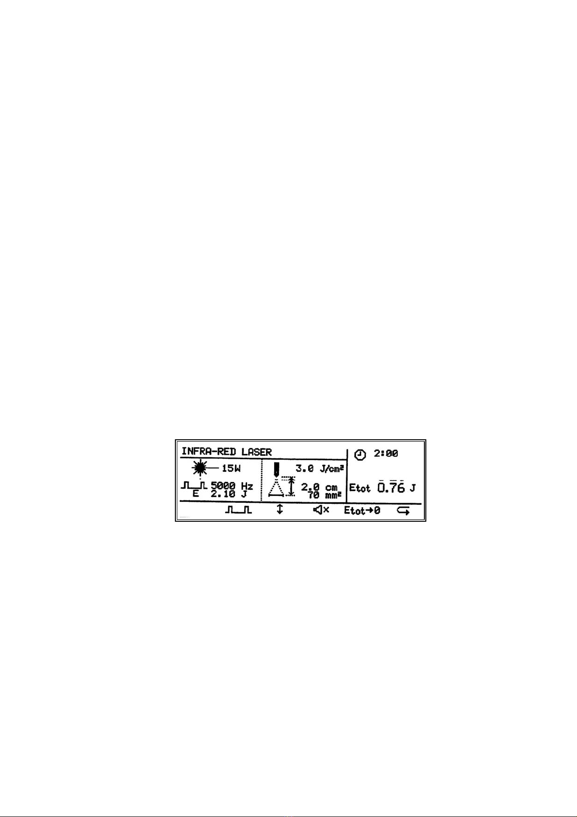
Infra-red laser beams are invisible. In order to check that the laser probe is operating correctly, a sensor7
is built in. This sensor is located to the right above the current output socket. Using application no. 903
the infra-red laser power can be tested. If the laser probe is held in front of the sensor, the measured
peak power will appear on the display. We advise you to perform such a measurement periodically, for
example monthly. When performing a treatment using laser therapy, the infra-red sensor can be used to
test whether laser energy is being emitted through the probe.
1.4.4 Knobs
On the front and to the right there are three potentiometers. When you turn these knobs fully anti-
clockwise, you will detect a click indicating that they are in the zero position. From the top to the bottom
the knobs have the following functions:
- Using the top knob8you can adjust the laser energy in Joules. The treatment time changes
automatically.
- The middle knob9is used to adjust the peak intensity in Watt/cm2for ultrasound.
- The bottom knob10 is the dose regulator for electrotherapy.
1.4.5 Push-buttons
- The blue buttons11 have a function which is different for each program and each menu. The display
indicates clearly whether the buttons have a function and, if so, which function.
- The black buttons ¿or À12 are used to increase or decrease the value of a parameter which you
have previously selected.
- The left hand yellow button13 is used to return to the main menu. If you hold down this button for a
few seconds you will arrive in a special menu STANDARD SETTINGS.
- Once you have selected a program, the right hand yellow button14 quickly and easily provides you
with further options of the selected program. Using this button you can call up the applications from
the main menu.
- Using the green button15 you can call up the special memory function. You can store, retrieve and
change 250 different treatments.
1.4.6 Output connectors and sockets on the front
The equipment is fitted with a number of connectors for the following functions:
- The two connectors16 on the far left are used to connect the laser probe(s). It does not matter to
which of the two connectors the laser probe(s) is/are connected.
- The two middle connectors17 are for connecting the ultrasound head(s). Here too it makes no
difference to which connector the head(s) is/are connected. You can connect two heads at the same
time.
- The two safety sockets18 on the far right are used for connecting the electrode cables during
electrotherapy. For combination therapy you can only use the socket on the far right, since in this
case the other socket is without current. In this case the metal treatment surface of the ultrasound
head forms the other electrode.
1.4.7 Key switch
When you want to switch on a program utilizing laser, you should turn the key switch19 to the right. To

Service Information Phyaction 740 & 790-series Page 5
switch off, turn the key to the left. To prevent the use of laser by unauthorized personnel, you should
remove the key from the equipment when it is not being used.
1.4.8 Operating elements on the rear of the equipment
The following operating elements are located on the rear of the equipment:
- Mains input with main switch20.
- Fuse holder21 between the mains input and the main switch. The rating of the fuse to be used is
stated on the rear of the unit.
- The serial in- and output22. These are for future extensions.
- Connector for potential mains equalisation23.
- Label with equipment data24.
1.4.9 Laser probes
Various laser probes25 can be supplied. When you have two probes, these can be connected to your
equipment at the same time. Using a blue button you select from the program which probe you wish to
use. A green lamp26 then illuminates on the selected probe. On the probe is a knob27, which has to be
pressed to allow laser light to be emitted. When laser light is being emitted, the yellow lamp28 on the
probe illuminates. For reasons of patient safety and correct operation of the equipment, the connection of
probes other than those supplied by Uniphy is not permitted.
If in doubt about the proper operation of your laser probe, you can check this by using technical
application no. 903.
Looking into the probe when laser light is being emitted can seriously damage the eyes.
Therefore, never look into the laser probe and never point it towards the eyes.
1.4.10 Ultrasound treatment heads
You have the choice of three ultrasound heads29 with an ERA (Effective Radiation Area) of respectively 1,
4 or 10 cm2. For each treatment head a multi-functional head holder30 is supplied. With each treatment
head both 1 and 3 MHz ultrasound can be given. Two treatment heads can be connected to the
equipment at the same time, provided the treatment heads do not have the same format. Using one of
the blue buttons you select which of the two heads you wish to use. A green lamp31 illuminates on the
treatment head as soon as it has been selected and a red lamp23 illuminates when the surface of the
head makes insufficient contact with the patient. The ultrasound power is then automatically adjusted
back so that overheating and subsequent wear of the treatment head is prevented. During insufficient
contact the treatment time also stops and when contact is made it continues. In this way the set time is
actually utilized.
Before using a new treatment head a one-off operation should be performed, using technical application
no. 902, to tune your equipment to the treatment head.
1.5 Technical specifications
The Phyaction 790-series consists of two models: the Phyaction 792 and 796. The same specifications
for the Phyaction 796 also apply to the Phyaction 792, however, the 792 model is not fitted with an IR-
laser.

Service Information Phyaction 740 & 790-series Page 6
1.5.1 Ultrasound therapy
General:
- Duty-cycle adjustable from 1:1 up to 1:15
- Power setting using potentiometer
- The unit calculates the total effective power and displays it on the LCD
- Option to tune the ultrasound head to the unit using a special program
- Option of combination therapy using one of the 4 options with electrotherapy current forms
- For each head a green lamp illuminates as soon as the head is selected
- During insufficient contact the ultrasound power is automatically reduced and a red lamp
illuminates on the head. The timer stops
- Reflected waves are partially absorbed by the heads to avoid intensity peaks
Specifications small treatment head (model 291):
- Frequencies: 0.8 MHz and 3.3 MHz
- BNR at 0.8 MHz: < 5
- BNR at 3.3 MHz: < 4
- ERA: 1 cm2
- Output power: 0 - 1.5 W/cm2at 3.3 MHz continuous
0-2W/cm
2at 0.8 MHz continuous
0-3W/cm
2at 0.8 and 3.3 MHz pulsed
Specifications large treatment head (model 292):
- Frequencies: 0.8 MHz and 3.3 MHz
- BNR at 0.8 MHz: < 5
- BNR at 3.3 MHz: < 4
- ERA: 4 cm2
- Output power: 0 - 1.5 W/cm2at 3.3 MHz continuous
0-2W/cm
2at 0.8 MHz continuous
0-3W/cm
2at 0.8 and 3.3 MHz pulsed
Specifications extra large treatment head (model 293):
- Frequencies: 1.0 MHz and 3.4 MHz
- BNR at 1.0 MHz: < 5
- BNR at 3.4 MHz: < 4
- ERA: 10 cm2
- Output power: 0 - 1 W/cm2at 1.0 and 3.4 MHz continuous
0 - 1.5 W/cm2at 1.0 and 3.4 MHz pulsed
1.5.2 Laser therapy
General:
- Pulse repetition frequency 2 - 5000 Hz
- Energy adjustable with potentiometer
- Operating distance 0 - 5 cm (for energy density calculation)
- Conversion of energy to energy density with given operating distance and calculation of treatment
area
- Test eye for checking power of the laser
- A green lamp illuminates when probe is selected and yellow lamp when probe emits energy
- Prior to accessing the laser program the key on the unit should be turned
Specifications 15 W probe (model 241):
- Peak power: minimum 12 W, maximum 18 W
- Max. average power: 12 mW
- Wave length: 904 nm (infrared)
- Laser class: 3B

Service Information Phyaction 740 & 790-series Page 7
- Pulse duration: 150 ns
- Beam diameter: 2.5 mm
- Divergence angle: approx. 20 degrees
- Dimensions: diameter 2.5 cm, length 21 cm
Specifications 25 W probe (model 242):
- Peak power: minimum 22 W, maximum 30 W
- Max. average power: 25 mW
- Wave length: 904 nm (infrared)
- Laser class: 3B
- Pulse duration: 200 ns
- Beam diameter: 4.0 mm
- Divergence angle: approx. 32 degrees
- Dimensions: diameter 2.5 cm, length 21 cm
Specifications 4x18 W probe (model 245):
- Peak power per diode: minimum 16 W, maximum 22 W
- Max. average power: 60 mW
- Wave length: 904 nm (infrared)
- Laser class: 3B
- Pulse duration: 150 ns
- Beam diameter: 4 x 2.5 mm
- Homogeneous intensity: from appr. 3 cm from the probe
- Divergence angle: approx. 20 degrees
- Dimensions: diameter 4 cm, length 22 cm
1.5.3 Electrotherapy
Parameters two-pole interferential current:
- Carrier wave frequency: 4000 Hz
- AMF: 1 - 200 Hz
- Spectrum: 0 - 200 Hz
- Time: 1 - 100 s
- Contour: 1 - 100%
- Output current: 140 mApeak maximum at 500 Ohm
Parameters, medium frequency surge current:
- Carrier wave frequency: 4000 Hz
- AMF: 1 - 200 Hz
- Stimulation time: 1 - 100 s
- Pause: 1 - 100 s
- Surge: 1 - 100%
- Output current: 140 mApeak maximum at 500 Ohm
- Choose from automatic or manual stimulation using pulsator
Parameters TENS current, continuous:
- Pulse time: 10 - 300 µs
- Pulse frequency: 1 - 500 Hz
- Spectrum: 0 - 200 Hz
- Time: 1 - 100 s
- Contour: 1 - 100%
- Output current: 140 mApeak at 500 Ohm
- Pulse form: asymmetrical
Parameters TENS current, burst:
- Pulse time: 10 - 300 µs
- Pulse frequency: 80 - 500 Hz

Service Information Phyaction 740 & 790-series Page 8
- Burst frequency: 1 - 10 Hz
- Number of pulses per burst: 5
- Output current: 140 mApeak maximum at 500 Ohm
- Pulse form: asymmetrical
TENS current, surge (Phyaction 793 only):
- Pulse time: 10 - 300 µs
- Pulse frequency: 1 - 500 Hz
- Train duration: 1 - 100 s
- Train interval: 1 - 100 s
- Surge: 1 - 100%
- Output current: 140 mApeak at 500 Ohm (at a pulse time up to 100 µs)
- Pulse form: asymmetrical
Continuous galvanic current (Phyaction 793 only):
- Output current: 80 mApeak at 500 Ohm
Interrupted galvanic current, rectangular or triangular pulse (Phyaction 793 only):
- Pulse time: 0.1 - 1000 ms
- Pause time: 2 - 9999 ms
- Output current: 80 mApeak at 500 Ohm
Faradic current, rectangular or triangular pulses (Phyaction 793 only):
- Pulse time: 0.1 - 1000 ms
- Pause time: 2 - 9999 ms
- Train duration: 0.05 - 100 s
- Train interval: 0.05 - 100 s
- Surge: 1 - 100%
- Output current: 80 mApeak at 500 Ohm
Ultra Reiz current (Phyaction 793 only):
- Pulse time: 2 ms
- Pause time: 5 ms
- Output current: 80 mApeak at 500 Ohm
Diadynamic currents MF, DF, CP, CP-ISO, LP (Phyaction 793 only):
- MF frequency: 5 - 200 Hz
- DF frequency: 2 x MF frequency
- MF time: 1 - 100 s
- DF time: 1 - 100 s
- Surge: 1 - 100%
- Output current: 80 mApeak at 500 Ohm
1.5.4 Further details
- Fully programmable memory with space for up to 250 treatment procedures and with battery back-
up
- Many recommended programs for simple application per indication
- You can set different operating languages yourself: Dutch, English, German, French, Italian and
Spanish
- Pre-programmed parameters can be changed to your requirements
- Treatment time adjustable to 30 minutes

Service Information Phyaction 740 & 790-series Page 9
- Acoustic monitor with volume control can be switched on
- Serial input and output for extensions
- Built-in electrode and cable test
- Solid metal casing (Faraday's cage)
- Ergonomically designed with very attractive appearance
- Simple to operate due to clear symbols and the availability of different languages on the display
- Dimensions: 41 x 28 x 13 cm
- Weight Phyaction 796: 6.5 kg (excluding accessories and packing)
Phyaction 740: 5.7 kg (excluding accessories and packing)
- Insulation class (790 series): I, type BF
Phyaction 740: I, type B
- Voltage: 110, 220, 230 or 240 Volt, 50-60 Hz
- Input current (790 series): maximum 300 mAeff at 230 V and 600 mAeff at 110 V
Phyaction 740: maximum 150 mAeff at 230 V and 300 mAeff at 110 V
1.6 Explanation of symbols
1.6.1 General
Indication of treatment time
Contrast
1.6.2 Electrotherapy
Output current
Two pole MF current
MF surge current
Biphasic current, continuous
Biphasic current, burst

Service Information Phyaction 740 & 790-series Page 10
1.6.3 Electrotherapy, parameter adjustments
Contour
Pulse time biphasic current
Frequency of biphasic current
Burst frequency of biphasic current
Stimulation time with MF surge current
Stimulation interval with MF surge current
Timing clock
Sound signal on/off
1.6.4 Ultrasound therapy
Selected ultrasound head, small, large, extra large
Duty-cycle
1.6.5 Ultrasound therapy, parameter adjustments
Selectable ultrasound head, small, large, extra large
Toggle ultrasound frequency
Duty-cycle
Timing clock
1.6.6 Laser therapy
Laser probe, 15W
Laser probe 25 W
Laser probe 4 x 18 W

Service Information Phyaction 740 & 790-series Page 11
Pulse repetition frequency
Turn key clockwise
Turn key anti-clockwise
1.6.7 Laser therapy, parameter adjustments
Selectable laser probe, 15W
Selectable laser probe, 25 W
Selectable laser probe, 4 x 18 W
Pulse repetition frequency
Distance between laser probe and skin
Set total energy to zero
Repeat function
Sound signal on/off
1.6.8 Treatment memory
Programmable memory
Store a therapy
Start a stored therapy
Clear a stored therapy
Information memory usage

Service Information Phyaction 740 & 790-series Page 12
1.6.9 Symbols on the front of the appliance
Memory function
Return to main menu
Options for this program
Raising the selected parameter
Lowering the selected parameter
Indication light for Stand-by
Indication light for stimulus
Indication light for detected errors
Current
"OFF" for a part of equipment
"ON" for a part of equipment
Laser
Ultrasound
Sensor for laser power measurement
Attention, see manual

Service Information Phyaction 740 & 790-series Page 13
INVISIBLE LASER RADIATION
AVOID EXPOSURE TO BEAM
CLASS 3B LASER PRODUCT
LASER APERTURE
15 Wpk/ 150 ns/ 904 nm
1.6.10 Symbols on the back of the appliance
Off
On
Fuse
Serial in- and output
Equipotentiality
Type BF
Do not open
Attention, see manual
1.6.11 Laser, warning symbol and explanatory labels
Laser warning symbol; on every laser probe
Explanatory label; on every laser probe
Explanatory label; on laser probe model 241

Service Information Phyaction 740 & 790-series Page 14
LASER APERTURE
25 Wpk/ 200 ns/ 904 nm
LASER APERTURE
4x18 Wpk/150 ns/904 nm
Explanatory label; on laser probe model 242
Explanatory label; on laser probe model 245
Type B
1.7 Photos of the current waveforms
Biphasic current, continuous
Two pole interference
MF surge current
Biphasic current, burst

Service Information Phyaction 740 & 790-series Page 15
CHAPTER 2 THEORY OF OPERATION
2.1 Introduction
In this chapter a description of the electronic construction of the Phyaction 790-series is given on the
functional level. Only where safety aspects are concerned we will look into the actual circuitry. The next
paragraph deals with the whole appliance and those blocks that are in use with all therapies. In the
subsequent paragraphs more detailed block diagrams for each kind of therapy will be discussed.
2.2 General block diagram
Figure 1 shows the functional blocks of the Phyaction 797VIP. The most extensive appliance of the
series. The microcontroller core controlling the entire appliance is featured in the middle. Immediately
below that are the blocks associated with the three therapies and the output panel. At the left there is the
user interface and at the right the serial interface. In the upper part there is the inevitable power supply.
The parallel interface which is only present in the VIP versions is also drawn here.
Figure 1, Functional blocks of the Phyaction 797VIP

Service Information Phyaction 740 & 790-series Page 16
2.2.1 Microcontroller core
As central processing unit a microcontroller is being used in favour of a microprocessor. The reason
being that a microcontroller, by its construction and available commands, is particularly suited for bit-level
operations. From the software point of view there is no difference but it is much easier to manipulate a
single I/O-pin. The microcontroller used in the Phyaction 790-series is the 80C552. It incorporates in
addition to the actual 8051 controller the following circuits:
- 256 Byte RAM
- 3 programmable timers
- 1 A/D-Convertor with eight multiplexed inputs and 10-bits resolution
- 5 I/O ports, each 8 bits wide
- 2 Pulse width modulators with 8-bits resolution
- 1 I²C-bus interface for internal data transmission
- 1 full-duplex UART (Universal Asynchronous Receiver and Transmitter)
- 1 Watchdog timer
Apart from this microcontroller the core contains the following devices:
- an 8-kbyte RAM with integrated lithium battery (NOVRAM)
- a 1-Mbit EPROM
- a programmable I/O-expander
- an analog multiplexer to increase the amount of ADC inputs
- some PAL's and HCMOS chips as decoders and buffers
2.2.2 User interface
A LCD (Liquid Crystal Display) with a console forms the major link in the communication between the
operator and the microcontroller. The display is connected directly to the microcontroller via the data-bus
and the keys of the console via the I²C-bus. The menus and program screens are shown on the display
and the operator selects the requested therapy with the buttons and also changes or enters parameter
settings with them.
2.2.3 Serial interface
A serial interface identical to that in the Phyaction 780-series is provided to be used with future
extensions. The way of operating is similar to that of the teletype current loop although the level of the
current has been reduced. The interface is fully isolated from the rest of the circuits in the appliance by
means of optocouplers with an isolation voltage of 2.5 kV.
2.2.4 Parallel interface
This unit, which is only present in the VIP versions, makes up the link between the LCD and the I/O-card
in the PC. Again using optocouplers with an isolation voltage of 2.5 kV to achieve full galvanic isolation,
the necessary control-signals are tapped and the data is synchronously stored in a RAM. This RAM in its
turn is being asynchronously read by the software running on the PC which subsequently reconstructs
the image shown on the LCD.
2.2.5 Power supply
The power supply is of a conventional linear design with a mains transformer for medical devices
followed by secondary fuses, bridge rectifiers and smoothing capacitors. From the unstabilised voltages
created in this way, the one called +29V is used to supply the power stages for the current generation
and the ultrasound generation. The other supply voltages, +24V, +15V, -15V and +5V (Vcc), are
stabilised by linear regulators with the latter three in addition being protected from overvoltages by
crowbars. A reset signal is issued to the microcontroller when the +5V (Vcc) is beneath the threshold

Service Information Phyaction 740 & 790-series Page 17
level for the logic ICs.
2.3 Electrotherapy unit
Figure 2 shows the functional blocks for the electrotherapy unit and the associated safety circuit. These
circuits are identical to the ones in the Phyaction 780-series. Just a minor simplification has been made
in the setting of the maximum current guarding because for the near future only generation of MF
currents and TENS is envisaged. Also as a consequence thereof the current-mode facility and the allied
switch-over options in the patient output circuit are not needed for the time being.
2.3.1 Waveform synthesis
The current waveform being selected, the microcontroller accordingly controls the waveform synthesizer
to yield the required waveform. The sample data of the waveform are stored in an EPROM and from
there transferred to the D/A-converters in the course of the phase. The magnitude of the resulting wave
is always proportional to the value of Vpot being set by the intensity control-knob because it is
established by modulating this control-voltage with multiplying D/A-converters.
2.3.2 Chopper
The main purpose of the chopper is to apply the waveform to one of the two inputs of the V/C-converter
and to establish in this way the polarity. With TENS the pulses are formed directly by activating the
chopper to pass its input voltage to one half of the V/C-converter.
In case of rectified current generation the chopper is operated on a substantially higher switch-rate and
the output current is rectified before being applied to the patient. The used switching rate yields an
unnoticeable current in case of a defective rectifier.
Figure 2, Functional blocks of the electro-therapy unit

Service Information Phyaction 740 & 790-series Page 18
2.3.3 Voltage to current converter
The voltage-to-current-converter (V/C-converter) converts, as the name indicates, the applied input
voltage into a linear proportional output-current. As it is conceived as a balanced stage it is easy to
determine the polarity of the output current by applying the controlling voltage to one of the two inputs.
The primary output current flows through a low-ohmic resistor. The voltage drop across this resistor is
proportional to the absolute magnitude of the actually generated output current and is fed to the safety
circuit.
In order to reduce the power dissipation in the actual V/C-converter it is powered through a so called
tracing series regulator. This regulator lowers the supply voltage to a level that just accommodates the
converter.
2.3.4 Safety circuit
The voltage drop sensed in the V/C-converter is used in this circuit to monitor whether the output current
oversteps the limits as stated in IEC 601-2-10 or 150% of the set value, whichever is smaller. In addition
the intensity control is monitored for interruptions of the ground terminal. This all is achieved fully
independent of the microcontroller by comparators that, in case of a fault, switch off the safety relay,
which interrupts the patient current circuit. This happens so fast that even in case the full supply voltage
is suddenly applied to one of the primary windings of the output transformer, the energy contents of the
resulting pulse will be well below the allowed limit. Once the safety relay has been switched off it remains
in this state and one must switch on the appliance after the cause has been removed, e.g. turned up
intensity control at switch-on.
Because on switch-on of the appliance a selftest is performed which of course includes a test of the
safety circuit, a way is provided for the microcontroller to switch on the safety relay. This is necessary as
the safety relay will be in the off state after switch-on and should also switch off a couple of times in the
course of the selftest. This possibility to switch on the safety relay is time limited however to 3 seconds
from power-on. When this time has expired the microcontroller only can switch off the safety relay, e.g.
when an error of another nature has been detected. In this way it is guaranteed for the safety circuit to
operate independently from the generation of the patient current and the software.
2.3.5 Current mode selection
As mentioned before it is also possible to generate rectified currents like diadynamic, Ultra Reiz,
galvanic, etcetera. To that object a rectifier is switched into the patient current circuit. The choice
between rectified and alternating currents is also sensed by the microcontroller to select the adherent set
of waveform options and waveform synthesizer control-signals. The rectifier circuit is only present in the
Phyaction 793.
2.4 Ultrasound therapy unit
Figure 3 shows the functional blocks for the ultrasound therapy unit. As the ultrasound power is
generated by switching, it appeared to be necessary to encapsulate the committed circuitry, from the PLL
(Phased Locked Loop) up to the impedance match and including the SSMPS (Secondary Switch Mode
Power Supply), in a tin case to meet the emission-limit requirements. This shielding extends itself over
the inner shield conductor of the treatment head cable up to the transducer which is mounted in a closed
aluminum cylinder.
This manual suits for next models
1
Table of contents
Other uniphy Medical Equipment manuals
Popular Medical Equipment manuals by other brands

Starck
Starck Sefam S.Box Patient manual

Joerns Healthcare
Joerns Healthcare hoyer ascend User instruction manual

Arjo
Arjo AtmosAir SAT 4000 Series Instructions for use

Otto Bock
Otto Bock 28U11 Instructions for use

Otto Bock
Otto Bock 4P862 Instructions for use

Invacare
Invacare Rectangular Pan Holder and Pan 9610-1 Installation

Denjoy
Denjoy iMate-II user manual

Halotherapy Solutions
Halotherapy Solutions HALO BOOTH Installation & operation manual

Dräger
Dräger Narkomed 3 Technical & service manual

Apex Digital
Apex Digital iCH Prime instruction manual

Microgem
Microgem Sal6830 user guide

Olympus
Olympus ESG-410 Quick reference guide