Unisystem U137 Series Use and care manual

Calibration of U137, U235 & 237 Series Weight Indicators. Date:141027 B01950 1(10)
Unisystem AB
Bergebyv. 24 Tel.: 0560-140 55 www.unisystem.se
685 34 TORSBY (Säte) Fax: 0560-101 25 info@unisystem.se
Index.
Page 1 Coarse gain, offset and response time. Keyboard functions at calibration. Calibration sequence.
Page 2 Calibration sequence.
Page 4 Calibration sequence.
Page 5 Calibration sequence. U2375 with tilt sensor. Restrictions for verified scales.
Page 6 Setpoints. Programmable serial output codes. Serial input.
Page 7 Transducer connector. U237 connector. U137 RS232 connector. Internal connectors.
Page 8 U2375 tilt transducer connector. Optional connectors.
Page 9 Precautions when installing! Flow measurement. Pictures.
Page 10 Pictures.
Coarse sensitivity (gain), offset and response time.
In order to make coarse adjustments of sensitivity, offset and low pass filter, the bottom panel must be removed
and the boards taken out. Be very careful with the flat cable to the front panel! All switches and jumpers are situated
on the main board behind the display board, under the shield. Normally these adjustments are not necessary.
The accuracy of the settings is better than 0.5%.
Input sensitivity, corresponding to 93700(0) AD-units: Response time to 0.1%, optional resistors:
S2: 1,3 3 1 2 on J15-16-17 Standard J15-16-17
2.673 1.663 1.021 0.634 mV/V 410ms R10, R15 removed.
2x4.99M 290ms 2x10M 2360ms
The offset is set by: 2x1.74M 206ms 2x4.99M 1180ms
JP10 3-6 5-6 4-5 1-4 2-5 on 2x715k 120ms 2x2.74M 648ms
JP11 off 0.000 0.314 0.410 0.508 0.821 mV/V 2x383k 75ms 2x1.74M 410ms
JP11 on -0.052 0.262 0.358 0.456 0.769 mV/V 2x169k 37ms 2x715k 200ms
The response time to 0.01% error is twice the time above.
The 3dB frequency in Hz is 1/(2.2 x the time above in seconds)
The following values are set at delivery: Sensitivity 2.673mV/V, offset -0.052mV/V and response time 410 ms.
Lower input sensitivity with no offset may be received by:
3.424mV/V for JP10 off, S2:1,3 on. Connect R11:12 to R11:13. Disconnect U11:8.
4.272mV/V for JP10 off, S2:1,3 on. Connect R11:6 to 11 and 12.. U12:1 to R11:10. Disconnect U11:8. (U2396)
U235 has a fixed offset of -0.069mV/V.
The sensitivity is 2.673mV/V but may be changed to 1.663mV/V (W5 cut off) or 1.021mV/V (W6 cut off).
There is a 3-pole filter with low ringing. The response time is 1.6 seconds or 0.5 seconds with S2:1, 2 and 3 on.
Keyboard functions at calibration.
The software calibration is performed via the serial input or the keyboard (U235 and older U2373 must have a
separate keyboard, U2395). The functions of the keys at calibration are as follows:
{ZERO} Steps forward one position in the calibration sequence. Previous step is stored.
{TARE} Steps back one position in the calibration sequence. Previous step is stored.
{NET/GROSS} Selects the digit position of data. In sign position, the NET indicator blinks.
Switches between increment and decrement in Cs1 to 22. (Cs = Calibration step).
{COUNT} Increments or decrements the digit value and changes sign.
{F} {ZERO} Cs23-25. Gets the signals AD-value. {F} immediately after gets the old value back.
Cs31, 32. Sets the displayed AD-value to zero e.g. at 0° tilt for easier calculation.
{F} {TARE} Extrapolates the AD-value in Cs25 from Cs23 and Cs24 when max weight is missing
{PRINT/TEST} Prints the calibration sequence and program information.
{F} {F} Returns to the AD-value (before Cs1). Skips change after {F} {ZERO} or {TARE}.
{F} {PRINT/TEST} {ZERO} Enters preset values marked * below, when the AD-value is displayed e.g. after {F} {F}.
Calibration sequence.
The calibration switch S1 is located on the bottom panel. When S1 is switched on, the software calibration mode is
entered and the 6 digit internal AD-value is displayed. U137 and U235 only presents the 5 most significant digits for
the AD-value.
In the following calibration sequence, the functions and calibration may be changed.
When S1 is switched off, the indicator enters weighing mode. Restart the indicator to get all changes.
The calibration sequence is also entered without S1 by {F}{ZERO}, 3 successive times (from 001127). Cs 01 to 15
may be changed but not the calibration. The sequence is left by {F}{F}.
The display shows XX NN. XX is Cs(Calibration step) for 01 - 22, 28 and 29. NN is the chosen function code.
= code cannot be used together with any other = code in the same Cs.
+ code can be combined with any other + code and one = code in the Cs.
Add all + codes and the = code to get the number NN to enter in the Cs.
* means preset data according to the above. New separate indicators are delivered with these values.
Steps 23 - 27 and 30 - 32 have more sub steps according to below.
Not used steps, may be used for special functions, and NN = 0 must be chosen.

Calibration of U137, U235 & 237 Series Weight Indicators. Date:141027 B01950 2(10)
XX NN Comment.
Serial outputs. Description in B01910.
01 =0 Output 1. Display, tare and mode indicators.
=1 Output 2. Display and mode indicators.
=2 Output 3. Display, tare, setpoints, and 16 bits binary DA-value.
=3 Weight and address is sent from more indicators in series. Data from all is received by entering a P (ASCII
80) in the first indicator. Individual data is received by {PRINT/TEST} on each indicator. See B01910.
=5 Programmable continuous serial output.
=6 Programmable serial output. For printer.
*=7 Display in ASCII. Net or gross. For printer. Each line ends with CR and LF.
=8 Display in ASCII. Net & gross. For printer. Each line ends with CR and LF.
=9 OIML for printer. Display in ASCII. Net or gross. Preset Tare PT. Each line ends with CR and LF.
=10 Not used.
=11 Special protocol, WMI. Only negative values.
=12 Display in ASCII with 6 digits and increment 1, every measurement cycle. Each ends with CR.
=13 AD mean value in ASCII with 7 digits every measurement cycle. Each ends with CR.
=14 Display in ASCII every measurement cycle. Each ends with CR.
=15 Output disabled, except in calibration mode.
02 *0 The zero of the binary data refers to the display (net or gross). Synchronous output 2. Serial output 3.
+1 The zero of the binary data refers to the gross value.
+2 Synchronous output 1 refers to actual LCD (U237) instead of LED (Old U137 and U1266).
+4 Peak value mode. Max and min values are stored. Counting scale function does not work.
Note! Can not be combined with Cs 20: =2, No limits on zero range.
+8 Not used.
03 =0 300 baud.
*=1 1200 baud.
=2 2400 baud.
=3 9600 baud.
+4 Not used.
+8 Not used.
04 *=0 No address. RS232.
=01-14 Address for RS422 or in Cs1:3&4. RS422 is addressed by |(ASCII 124) 1 to 14, [CR].
No one is addressed by | and character other than 1 to 9. [CR] is recommended.
=15 Always addressed. Used for single RS4225 unit without address command.
Special functions.
05 *=0
+1 Not used.
+2 Not used.
+4 Not used.
+8 Not used.
Mean value.
06 =0-3 *3 Full mean value 1, 2, 4 or 8 measurements when all are within mean value band.
+4 Not used.
+8 Not used.
07 =0-7 *3 Mean value band. Infinite, 0.25, 0.5, 1, 2, 4, 8, 16 intervals.
For standard scales, use a value approximately equal to the total number of intervals divided by 3000.
+8 Not used.
08 =0-7 *4 Measurement time. 60, 100, 200, 400ms, 1, 2, 5, 10 seconds. Some functions e.g. low baud rate inter-
fere with the shortest times.
+8 Not used.
Unstable weight. (Motion.)
09 *0 Stable weight after 2 successive measurements within motion band. Printing, tare and zero executed after
the weight becomes stable. No blanking at unstable weight.
+1 Always printing at unstable weight.
+2 Last digit is blanked at unstable weight. Last digit is represented by M on the serial output.
+4 Stable weight after 3 successive measurements within the motion band.
+8 The display is blanked at unstable weight.
10 =0-7 *3 Motion indication band. Infinite, 0.25, 0.5, 1, 2, 4, 8, 16 intervals.
For standard scales, use a value 0.5 to 1 times the mean value band in Cs07. According to OIML the max
weight change is 1.5 intervals during 5 seconds after the end of unstable weight.
+8 Not used.
Zero functions. Zero range is -0.8 to +3.1% of Max.
11 0 Normal printing. Zero tracking condition. 8 successive measurements within ±1/2 interval.
+1 Unload to zero before new print.
*+2 Automatic zero set at power on.
+4 Zero tracking condition. 16 successive measurements within ±1/2 interval.
*+8 Zero tracking condition. 32 successive measurements within ±1/2 interval.
+12 No zero tracking.
12 =0-7 *3 Max zero tracking change. 0, 0.25, 0.5, 1, 2, 4, 8, 16 intervals.
+8 Not used.

Calibration of U137, U235 & 237 Series Weight Indicators. Date:141027 B01950 3(10)
Miscellaneous functions.
13 *=0
=1 Difference (flow) calculated at a signal on the CTS input, J1:9. See page 9 and B01521. No count mode.
=2 Difference (flow) calculated every measurement cycle. See page 9 and B01521. No count mode.
=3 Difference (flow) calculated every 100 measurement cycle. See page 9 and B01521. No count mode.
+4 Not used.
+8 Not used.
14 *0 Setpoints are compared with displayed weight. For fast setpoints, use short measurement time in Cs08.
+1 Setpoints are used for over load and compared with gross value. On time delay is between 1 and 2 times
the measurement time according to Cs08. Off time delay is 8 times the measurement time.
+2 Not used.
+4 Not used.
+8 Not used.
15 *0 No battery timer.
+1 Leading zero blanking. For U235 series.
+2 Not used.
+4 Battery timer 64 measurement times time in Cs08.
+8 Battery timer 256 measurement times time in Cs08.
+12 Battery timer 1024 measurement times time in Cs08.
The timer is reset at button push or weight change more than 8 times the motion band. U235 & U2372.
16 *=0 .
+1 Not used.
+2 Not used.
+4 Not used.
+8 Not used.
Calibration.
17 =0 x x x x x .
=1 x x x x . x
*=2 x x x . x x
=3 x x . x x x
=4 x . x x x x (Not display for U237)
=5 No decimal point.
+8 TARE is combined ZERO and TARE button. For U235 & U2373. All other buttons works as normal.
1
18 *=0 1 Verification scale interval (increment) e or e at multiple range.
=1 2
=2 5
=3 10
=4 20
=5 50
+8 Only LED indicator is sent out on synchronous output. (Gives more stable display.)
19 *=0 Single range. Below the range change in % of max gross weight as function of min interval.
=1 2 ranges: 1 at 50%. 2 at 40%. 5 at 50%.
=2 3 ranges: 1 at 20 & 40%. 2 at 20 & 50%. 5 at 25 & 50%.
=3 4 ranges: 1 at 10 & 20 & 50%. 2 at 10 & 25 & 50%. 5 at 10 & 20 & 40%.
=4 5 ranges: 1 at 5 & 10 & 25 & 50%. 2 at 4 & 10 & 20 & 40%. 5 at 5 & 10 & 20 & 50%.
=5 6 ranges: 1 at 2 & 4 & 10 & 20 & 40%. 2 at 2 & 5 & 10 & 20 & 50%. 5 at 2.5 & 5 & 10 & 25 & 50%.
=6 Not used.
=7 Calibrated value with one additional digit and always 1 in interval. Not U1370 and U235.
+8 Multiple range change to range 1 is made only at zero indication. Range up is locked at stable weight.
Range indication. U137, U235: 1 no; 2 lower; 3 upper; 4 lower + upper right indicator on. U237: Range 1
none; 2 low; 3 +middle; 4 +high; 5 +low left; 6 +low right segment on, last digit. +, add to previous range.
1
Zero range is up to ±2% of Max .
The advantage of more ranges is a faster scale and less sensitivity to tilt.
For legal scales the following data must be met in the test certificate of the load cell (See B01990):
n1 max
Max /e #2.5Z. Z = E /2DR. DR = Min dead load output return. If there is no Z in the load cell test
certificate, Z = 1000x may be used, where x is from load cell accuracy class designation Cx.
n
Max may be set according to Cs21.
max 1 max max min min
EA/N/e #Y. E = Max load cell capacity. N = Number of load cells. Y = E /v . v = Min verifica-
min
tion scale interval. Y or v from the load cell test certificate.
max exc 1 exc
1000@C/E @U/N@e $0.6 :V. C = Output in mV/V. U = 10V except U2379, which has 5V.
20 *=0 Normal calibration for scales. Lower respective upper horizontal segments in the display are on when inside
AD-converter range below respective above the calibrated range.
=1 No zero functions. Full AD-converter range is used.
=2 No limits on zero range. Multiple range also works at decreasing weight.
Note! Can not be combined with Peak value mode Cs2: +4.
=3 Inverted calibration (for displacement level meters). No zero functions. Full AD-converter range is used.
=4 As Cs19:+8 but change to low range is made at zero or negative gross weight.
+8 If the last decimal at multiple range is a non-significant zero, it is blanked.

Calibration of U137, U235 & 237 Series Weight Indicators. Date:141027 B01950 4(10)
n-1 n
21 *=0 If fewer intervals in the highest range is wanted, Max is chosen here and Max in Cs24 or Cs25.
Possible ranges in the following table.
n-1 1
Max Intervals n per range (except highest range) for e (Cs18) and number of ranges in (), (Cs19).
1(2) 1(3) 1(4) 1(5) 1(6)
2(2) 2(3) 2(4) 2(5) 2(6)
5(2) 5(3) 5(4) 5(5) 5(6)
10(2) 10(3) 10(4) 10(5) 10(6)
20(2) 20(3) 20(4) 20(5)
50(2) 50(3) 50(4)
=1 3000 3000 1500 600 300 150
=2 4000 4000 2000 800 400 200
=3 5000 5000 2500 1000 500 250 100
=4 6000 6000 3000 1200 600 300 120
=5 8000 8000 4000 1600 800 400 160
=6 10000 10000 5000 2000 1000 500 200 100
=7 12000 6000 2400 1200 600 240 120
=8 15000 7500 3000 1500 750 300 150
=9 16000 8000 3200 1600 800 320 160
=10 20000 10000 4000 2000 1000 400 200 100
=11 25000 5000 2500 1250 500 250 125
=12 30000 6000 3000 1500 600 300 150
=13 40000 8000 4000 2000 800 400 200
=14 50000 10000 5000 2500 1000 500 250
=15 60000 6000 3000 1200 600 300
500#n #10000 Class 100#n #1000 Class
22 *=0
+1 Not used.
+2 Not used.
+4 Not used.
+8 Not used.
Cs 23 to 25 each have three part steps: 1. Step number. 2. Calibration weight. 3. Corresponding AD-value.
23 First calibration point (lowest AD-value).
*00000 Display data 1. Must be an even number.
*008000 Internal AD-value 1. U137 and U235 only presents the 5 most significant digits for the AD-value.
24 Second calibration point.
*10000 Display data 2. Must be even number. One digit increase must be > 1.25 AD-units and < 5000 AD-units.
*945000 Internal AD-value 2. (100.00% = 937,000 units change in AD-value)
25 Third calibration point.
*00000 Display data 3. Must be even number.
*000000 Internal AD-value. Cs25 is not used, when this value is lower than that in Cs24.
Full AD-converter range is from 1480 to 980020, but only values between 7960 and 945060 are allowed (no mode
indicators on) at the calibration. Values above 700000 gradually increase the response time. Note! U137 and U235
only presents the 5 most significant digits for the AD-value.
Negative data (for temperature meters) may be entered in Cs23. However when one step shall be changed, all
three must be entered again in increasing order.
26 Gravity g at place of calibration in m/s . 9.8186 is g at our factory in Torsby.
2
*9.8186 May be changed: 6.5537 #g #13.1071.
27 Gravity g at end user in m/s . If Cs26 = Cs 27, there is no correction.
2
*9.8186 May be changed: 6.5537 #g #13.1071.
Variation of g due to latitude ".
The 1980 formula is recommended. It is based on WGS 84. "is the latitude.
g = 9.780326777(1 + 0.0052790414 sin "+0.0000232718 sin "+0.0000001262 sin ") m/s
2462
The gravity g is changing most rapidly with latitude at 45° and is rather stable at the poles and equator.
Latitude: 0° Equator 30° 45° 60° 90° N pole )g, 0° to 90°
g 9.7803 9.7932 9.8062 9.8192 9.8322 0.0519
An common alternative for m/s is mgal or even µgal. gal is from Galileo. 1 mgal = 0.00001m/s .
22
Variation of g due to height.
When the formula above is used for calculation of g, the best average height correction value is:
)g = - 0.003h m/s , where h is height in km.
2
There is also a variation due to density of the ground and the thickness of the light earth crust.
This is normally lower than 0,001m/s . It is called Bouguer anomaly when the height correction -0.002h is used.
2
See also B01150 and our catalogue.

Calibration of U137, U235 & 237 Series Weight Indicators. Date:141027 B01950 5(10)
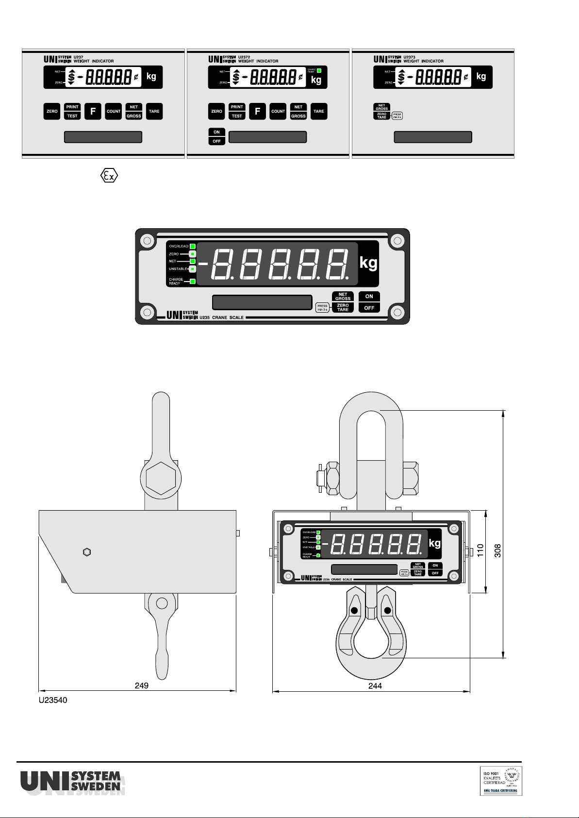
U2375 with optional tilt sensor U9027.
This indicator has 5 additional calibration steps, Cs28 to Cs32.
A cosine (square) compensation is made on the AD-value minus ADZ in Cs30. ADZ is the load cell AD-signal
without any load. AD-values < ADZ are not compensated.
A sine (linear) compensation may be entered for each direction in Cs31 and Cs32 respectively.
28 *=0 No tilt compensation. Only in U2375. P = pitch (Input PE5 on the processor) , R = roll (Input PE6).
=1 Max P and R = ±9.8° (17.0%). -9.8° = 0.026V, 0° = 1.315V, 9.8° = 2.604V. Standard tilt transducer U9027.
=2 As Cs28:1 but the display is blanked at 10% tilt. (Code =2 to =7 works only with program
=3 As Cs28:1 but the display is blanked at 8% tilt. dated 070207 or later)
=4 As Cs28:1 but the display is blanked at 7% tilt.
=5 As Cs28:1 but the display is blanked at 6% tilt.
=6 As Cs28:1 but the display is blanked at 5% tilt.
=7 The display is blanked at high on input PE4 on the processor in U2375
29 *=0 For the control of TARE and PRINT in e.g. automatic emptying equipment in refuse lorries.
=1 Tare signal at P = -9.4°. Stop at 4.7°, when the tare is not performed due to unstable signal.
Print signal at P = 9.4°. Stop at -4.7°, when the print is not performed due to unstable signal.
=2 As above but ±7.1° and ±3.0° respectively.
=3 As above but ±4.7° and ±2.4° respectively.
+4 Not used.
+8 Not used.
30 *29000 ADZ May be set from 1600 to 52600 in steps of 200.
ADZ corresponds to the AD-value without any load. The best way is to connect the load cells, tilted 90°, and enter
Cs30 before mounting. If the signal is outside the range, adjust with a high resistor between signal and excitation.
E.g. an ADZ, which is higher than correct value, results in too low tilt compensation. This negative error is inde-
pendent of load and constant, when tilted the same in all directions. It varies with the square (cosine) of the tilt angle.
Note! ADZ in Cs30 must always be entered before Cs31 & 32 . Else the adjustment is very difficult.
31
0.00 Tilt angle, P.
000000 AD-value.
P
±00000 Q
32
0.00 Tilt angle, R.
000000 AD-value.
R
±00000 Q
For compensation of linear (sine) errors, which change sign with angle.
Tilt angle and AD-value are indicated in sub step 1 and 2 respectively.
Q and sign are calculated from the formula below. This is done in both directions P and R.
The load receptor is tilted to equal positive and negative angles. The total change is )angle.
The AD-values are noted for zero angle and both tilts and used in the formula.
The calibration can not be left with S1 when displaying angle.
These errors are caused by different angle between tilt sensor and load cell(s) and by the side force sensitivity of
the load cell(s). Use a model with low side force sensitivity. Single point and shear beams, especially dual type, are
mostly good. (The side force is equal to the load times the tilt in percent.)
It is important that the load cell mounting is properly made. Multiple load cells bolted together, without any conve-
nient load transmission device, will have bad repeatability in the order of 0.1% or worse. The proper function of the tilt
compensation is then very difficult to measure and adjust.
Standard mountings from the load cell manufacturers are mostly not constructed for side forces.
Try to use load cells, which have small or at least equal side force sensitivity.
out out out
In order to get small change at eccentric loads, use current matched load cells (V /R = I equal).
Q and sign is calculated according to the following formula:
0 angle +angle -angle
Q @(AD-value - ADZ) @)angle @10 = AD-value - AD-value
-6
)= total change with positive sign.
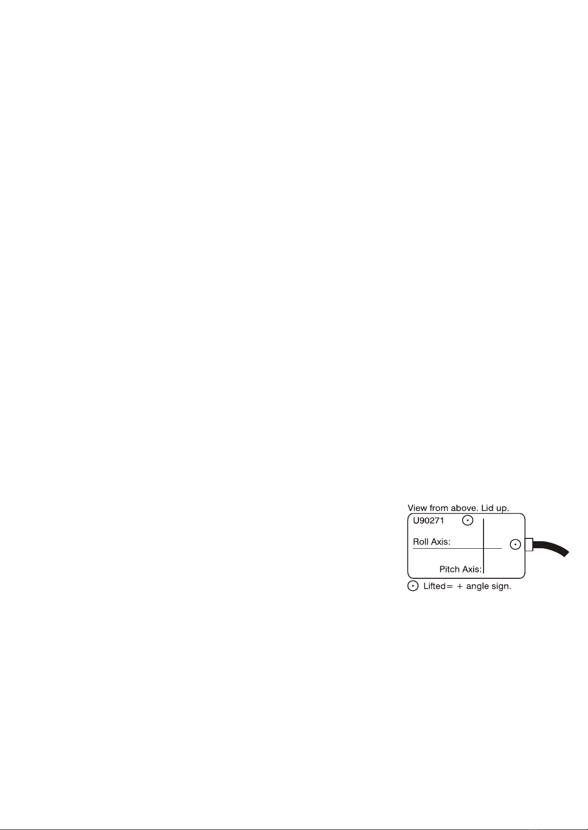
When the tilt transducer i s mounted according to the picture, a too high
+angle -angle
AD-value (and too low AD-value ) is compensated by a positive Q.
Keep the tilt position with weight loaded and enter Q. Leave the calibration
and check that the weight is properly compensated.
.
Example:
E.g. AD-values for -9°, 0° and +9° angle are 498200, 500000 and 502200.
The linear error is -2000 to +2000 units.
The square error is +200 AD-units, if present for P and R independent of load.
Then Cs30 is too low and an overcompensation is made. It must be increased by 200/(1-cos 9) = 16200 units..
Assume ADZ = 20000. Then Q@(500000 - 20000)@18 @10 = 502200 - 498200. Thus Q = +00463.
-6
Do never touch the potentiometers in the tilt transducer U90271.
Restrictions for verified scales. OIML R76-1 Ed. 92 (EN 45 501), paragraph number in ( ).
Cs01:=9 Should be used, when PT (Preset Tare) is used. (4.6.11). The reason for this and what shall be done with
the information is not mentioned.
Cs08:=5 Max 1 second. (4.4.1).
Cs09:+0 No printing at unstable weight. (4.4.5).
Cs11,12 Zero setting only minus weight (4.5.6). The reason for this is not mentioned. Zero tracking, max change
0.5 e/second. (4.5.7).
Cs19:+8 According to (4.10) for multiple range scales. For good load cells Cs20:=4 is an alternative.
Cs20:+8 According to (4.2.2.2 last paragraph) for multiple range scales. Reading difficult. Reason?
Cs23-25 Calibration weights (3.7.1), (3.7.3).
Cs24,25 Max +9e above verified max weight. (4.2.3).
Cs26,27 Gravity. WELMEC 2 Issue 3: 3.3.
Cs28 Tilt range. (3.9.1.1) says 5%. WELMEC 2 Issue 3: 3.1.13 says 10%.

Calibration of U137, U235 & 237 Series Weight Indicators. Date:141027 B01950 6(10)
Setpoints, Time, Date and Programmable Serial Output. Keyboard functions.
{ZERO} Steps forward in the sequence. Stores previous value in the EEPROM.
{TARE} Steps back in the sequence. Stores previous value in the EEPROM.
{NET/GROSS} Selects the digit position of the data. In sign position, the NET indicator blinks.
{COUNT} Increments the digit value and changes sign at setpoints.
{PRINT/TEST} Prints the sequence and leaves it.
{F} {F} Leaves the sequence.
Setpoints. By pushing {ZERO} and {TARE} simultaneously, or sending V or v, it is possible to enter 2 setpoints
(must be even numbers). First setpoint 1 is displayed. After {ZERO} setpoint 2, indicated by COUNT PCS on.
Output interface for the setpoints are described in B01900.
Time. U237. Push {F} {COUNT} {ZERO} and hhmmss for hours, minutes and seconds is displayed. Change time.
Date. U237.Push {F} {COUNT} {COUNT} {ZERO} and yymmdd for year, month and day is displayed. Change date.
Both are left by {F} {F} or {PRINT/TEST}.
Programmable serial output. By pushing {F} and then {PRINT/TEST} a sequence is entered. NNXXX is dis-
played, where 00 #NN #59 is a sequence number and XXX is the decimal value for the ASCII character or the
special function code according to below. The data are executed in the order they are entered.
Cs01:05 means that the string is sent continuously and Cs01:06 that the string is sent on print command.
Function codes:
000 Last character in the string. 000 and following characters are not sent.
176 Gross weight.
177 Net weight.
178 Displayed value, net, gross.
179 (AD8- and hexvalue from voltage on PE7. LOP = low power. Reset after 256 measurements.) For test.
180 Tare value.
181 Weight > setpoint 1, >1 is sent, else <1. For test.
182 Weight > setpoint 2, >2 is sent, else <2. For test.
183 Sign, 6 digit value and decimal point according to Cs19:=7.
184 Multiple range digit from 1 up to 6.
185 O/space (ASCII 79/32) for overrange/normal operation.
189 Date as dd - mm - 20yy, where yy are the two last digits of the year, mm month and dd day. Option.
190 Time as hh : mm : ss, where hh are hours, mm minutes and ss seconds. Option.
191 Date as 20yy - mm - dd, where yy are the two last digits of the year, mm month and dd day. Option.
192 Weight/unit in g.
193 5 digit value for setpoint 1.
194 5 digit value for setpoint 2.
195 Units net. Net weight/(weight/unit).
196 Displayed value without sign and decimal point, only 5 digits.
197 X (ASCII 88) is written on negative transition on IRQ, else space (ASCII 32). For test.
198 Tilt angle. Pitch on PE5. U2375. For test.
199 Tilt angle. Roll on PE6. U2375. For test.
200 Digit 4, most significant.
201 Digit 3.
202 Digit 2.
203 Digit 1.
204 Digit 0, least significant.
205 Sign, -/+ (ASCII 45/43).
206 Sign, -/space (ASCII 45/32).
207 Gross = 1 (ASCII 49), net = 2 (ASCII 50).
208 M/space (ASCII 77/32) for unstable/stable weight.
209 N/G (ASCII 78/71) for net/gross.
210 T/space (ASCII 84/32) for tare/no tare.
211 Z/space (ASCII 90/32) for zero/outside zero.
Serial input.
The serial buffer in the indicator is 12 bytes.
DTR on the serial output is set low when 11 bytes are stored in the buffer.
Only characters according to below are used. Other are ignored and the buzzer does not sound.
Decimal ASCII value of the character in ( ). Small letter may also be used.
Key F ZERO PRINT/TEST TARE NET/GROSS COUNT
ASCII sign F (70) Z (90) P (80) A (65) N (78) C (67)
xxxxxx E Only the entered number xxxxxx (up to 6 digits) is sent. Else as for P.
xxxxxx P The weight or number of pieces in counting mode is preceded by the number xxxxxx.
The number is displayed one measurement cycle.
Note! Other used ASCII character than digit, P, E or CR (13) resets the input buffer. CR is ignored.
F A x A The tare value x is entered, and the indicator displays the net value.
B(66) Enters always gross mode.
F fc P The indicator transmits the value according to the two last digits of the function codes (fc) 176 to 178,
180, 183, 184, 189 to 199 above. With {F} {COUNT} the fc (two last digits) may be entered manually.
F 60 P Program EPROM number, date, check sum, calibration sequence is sent on the serial output.
F 01 P Tilt angle, pitch on PE5 continuously. Angle and gross weight with P. Leave with F F.
F 02 P Tilt angle, roll on PE6 continuously. Angle and gross weight with P. Leave with F F.

Calibration of U137, U235 & 237 Series Weight Indicators. Date:141027 B01950 7(10)
Additional serial input functions at calibration or programmable serial output sequence:
F 50 P The indicator switches to and from transmitting the calibration sequence help text when stepping in
the calibration sequence.
F n Z (or A) Jumps to calibration step n in the sequence. Two consecutive jumps are allowed, then it restarts.
m Z (or A) Enters value m in the step and goes to the following or preceding step. At the programmable serial
output sequence, the values are also stored in the EEPROM.
V(86) Enters programmable serial output sequence. Corresponds to {ZERO} and {TARE} simultaneously.
RS422. The serial input is activated by |(ASCII 124) and 1-14 and [CR] (ASCII 13). Address 1-14 in Cs04.
All inputs are deactivated by | [CR].
Note! Never communicate to other equipment with an indicator addressed and do not use the character |else.
Connectors.
J2: Transducer connector. 9p D–sub female.
1
2
3
4
5
6
7
8
9
+SIGNAL
–SIGNAL
0VA Analog zero.
+SENSE
+EXC Excitation.
GND Ground/shield.
+5VA
–SENSE
–EXC Excitation.
NOTE! The body of the transducer (load cell) must be grounded!
The input amplifier is easily destroyed, when an electrostatic discharge occurs on
an ungrounded transducer, with power on the indicator. There is a great risk,
when an unmounted load cell is tested separately, as there normally is no inter-
nal ground connection. More regarding this below under precautions.
Use shielded cable, preferably double shielded, and filter D-sub.
For non symmetric load cells, +excitation to signal voltage must be higher than
signal to –excitation! If not, change all polarities.
Excitation voltage 10V ±1%. However U2379 5V±1%.
Connect GND to metal hood of D-sub.
J3: U237 series. Power/interface connector. 9p D–sub male. B01910.
1
2
3
4
5
6
7
8
9
0V Return for J3:2
Power +V
0VD
+VB (+V after fuse)
TD
Ground/shield.
RD
CTS
DTR
J3:2. 11 - 26V. opt. 29V. Always connect direct to the battery, when there is a
pp
risk of parallel inductive loads. Ripple >0.1V increases variation (slow jitter).
U2372. Charge battery on +V via series diode. +VB is battery voltage after the
internal fuse for e.g. printer. When 0VD is used for return, +VB is switched on/off
by the indicator. Max 0,5A, 1A intermittent.
Note! The asynchronous output pin configuration does not correspond to RS232,
but the signal level is standard. Option U1731, RS232 with 25p D-sub.
No asynchronous signals in U2373 and U2379.
Use shielded cables.
Connect GND to metal hood of D-sub.
J3: U137 series. RS232 interface connector. 9p D–sub male. B01910. Option U23890: RS422.
1
2
3
4
5
6
7
8
9
J4:1
RD
TD
DTR
0VD, J4:2
RS422 Rx A. J4:3.
RS422 Rx B. J4:6.
RS422 Tx A. J4:5.
RS422 Tx B. J4:4.
J4 is for optional signals.
RS422 is option. Full duplex.
Use shielded cable and terminating resistors at the cable ends.
Connect GND to metal hood of D-sub.
J1: Internal I/O connector except U2373.
1
2
3
4
5
6
7
8
9
10
11
12
13
14
15
16
GND
0VD
+5V
TARE
NET/GROSS
COUNT
F
PRINT/TEST
ZERO
(TD)
(DTR)
(RD)
(CTS)
SYNC D2
SYNC D1
SYNC CK
Connect to 0VD for function. R=10k
U237, RS232 level. U137, inverted, 5V CMOS level.
Synchronous data 2. HCMOS level. B01900,
Synchronous data 1. HCMOS level.
Synchronous clock. HCMOS level.

Calibration of U137, U235 & 237 Series Weight Indicators. Date:141027 B01950 8(10)
J9: U137/237 series main board. Interface connector for keyboard and display. 15p D–sub female. Obsolete.
1
2
3
4
5
6
7
8
9
10
11
12
13
14
15
Ground/shield.
ZERO (yellow)
PRINT/TEST (pink)
F (brown)
COUNT (grey)
NET/GROSS (white)
0VD (red)
TARE (black)
0VD (blue)
5VD (violet)
Disp D (red/blue)
Disp CK (grey/pink)
Disp CE(white/yellow)
0VD (green/brown)
5VD (white/green)
Connect GND to metal hood of D-sub.
Standard internal signals.
Max recommended distance to display 1m, keyboard 10m.
Pin 14 and 15 are backlight excitation of the display.
J9: U2375. Interface connector for Tilt Sensor U9027. 15p D–sub female.
1
2
3
4
5
6
15
10VA
0VD
0VD
Pitch
Pitch 2
Roll
Ground/shield.
Max 10mA.
Use large cable area. Max 5mV voltage drop in cable.
-"-
To PE5 of the processor in U2375.
For external applications.
To PE6 of the processor in U2375.
Connect to metal hood of D-sub.
J8: U137/237 series. U17310/1/3: RS232. U17310/3: Synchronous outputs. U17310: Optoisolated tare&print
inputs. 25p D–sub male.
1
2
3
5
7
8
10
11
12
13
14
16
18
19
20
22
23
GND
TD
RD
CTS
0VD
+5VD, max 25mA
SYNC CK
SYNC D1
SYNC D2
TARE
PT RET
PRINT/TEST
DTR
Connect to metal hood of D-sub.
RS232 B01910. U137 has inverted TTL output. Use J3 for RS232.
RS232 U137 has inverted TTL output. Use J3 for RS232.
Not U17311/3.
Synchronous clock. HCMOS level. B01900. Not U17311
Synchronous data 1. HCMOS level. Not U17311
Synchronous data 2. HCMOS level. Not U17311
Optoisolated 10 kohm input +10 - +30VDC. Not U17311/3
Return of PRINT/TEST and TARE signal.
Optoisolated 10 kohm input +10 - +30VDC. Not U17311/3
RS232 U137 has inverted TTL output. Use J3 for RS232.
J8: U137/237 series. U1734: RS422. Synchronous outputs. Optoisolated tare&print inputs. 25p D–sub male.
1
2
3
5
7
9
10
11
12
13
14
16
18
19
20
22
23
GND
0VD
RD A
RD B
+5VD, max 25mA
SYNC CK
SYNC D1
SYNC D2
TARE
PT RET
PRINT/TEST
TD A
TD B
Connect to metal hood of D-sub.
RS422
RS422
Synchronous clock. HCMOS level. B01900.
Synchronous data 1. HCMOS level.
Synchronous data 2. HCMOS level.
Optoisolated 10 kohm input +10 - +30VDC.
Return of PRINT/TEST and TARE signal.
Optoisolated 10 kohm input +10 - +30VDC.
RS422
RS422
Important! In order to avoid EMC problems, all external cables must be shielded. The D-sub hood must be of metal
or metalized with the shield connected. External boxes of metal (metalized) with the shield connected.

Calibration of U137, U235 & 237 Series Weight Indicators. Date:141027 B01950 9(10)
Precautions when installing!
The transducer signal inputs are easily damaged and must not be touched or left open with power on.
0VD is connected to 0VA. Both must only be connected to GND once, normally in the power supply at W1.
Shielded cables must always be used, J2 preferably double shielded, with twisted, shielded pairs. The shields must
always be connected at both ends. It is normally not done inside the transducer. The cable hoods must be of metal or
metallized and connected to the shield at the cable clamp. Filter D-sub, especially J2, improves the immunity against
strong radio frequency signals. Heavy electrostatic discharge may happen, when weighing big containers, trucks,
plastic material or cases, especially when moving and in winter time. In this case, a separate ground cable, 2.5 to
10mm , must be drawn parallel with the transducer cable to a screw on the indicator case.
2
All external connections must be made in separate grounded metal boxes.
Beware of high temperature sources, as the signal is very sensitive to temperature gradients.
The indicator must be well protected against high humidity, dust and dirt. Avoid to touch the boards.
When the displayed weight is unstable, always check connections, especially shield and ground.
Weight change (flow) function.
The weight change with respect to an external signal or during an internal time, selectable between 0.1 and 1000
seconds, may be measured with U137 and 237 series indicators.
Cs13:=1 Change with respect to a signal on the CTS input, minimum 100ms long.
Cs13:=2 Change every measurement cycle.
Cs13:=3 Change during 100 measurement cycles.
If )W is the displayed weight change, the average weight change per second is:
Cs13:=2 Cs13:=3 Cycle s
Cs08:1
Cs08:4
Cs08:7
Cs08:1
Cs08:4
Cs08:7
10)W
)W
)W/10
)W/10
)W/100
)W/1000
0.1
1
10
10
100
1000
{F} {NET/GROSS} switches between gross weight mode and weight change mode.
The weight change mode is indicated by the COUNT indicator.
Count mode does not work.
The setpoints are compared with the displayed weight change, if Cs14:0 is chosen.
No mean value is calculated.
Pictures:
U1370
U2370 U2371 U2372 U2373
U2375 U2379

Calibration of U137, U235 & 237 Series Weight Indicators. Date:141027 B01950 10(10)
Unisystem AB
Bergebyv. 24 Tel.: 0560-140 55 www.unisystem.se
685 34 TORSBY (Säte) Fax: 0560-101 25 info@unisystem.se
Old display.
U2370 U2371 U2372 U2373
U2375 U2379
U235 for crane scales.
Application of U235
This manual suits for next models
9
Table of contents
Popular Accessories manuals by other brands

Digitus
Digitus DA-70623 Quick installation guide

Intelbras
Intelbras IVP 2000 SF user manual

ROSE DISPLAYS
ROSE DISPLAYS ANOMULTI WITH WINDOW MOUNTS manual

AGS
AGS Merlin User & installation manual

IFM Electronic
IFM Electronic PN2 Series operating instructions

Somogyi Elektronic
Somogyi Elektronic Home DBP 01 user manual

e2 elektro
e2 elektro TRADITIONAL DNS-206 manual

Klarstein
Klarstein OLD MARSHALL manual

Be Cool
Be Cool BC23GSDT2 Operation manual

Optima Scale
Optima Scale OP-905 user manual

Spirax Sarco
Spirax Sarco SSC20 Installation and maintenance instructions

PCB Piezotronics
PCB Piezotronics 208A35 Installation and operating manual