Unit UT8803 User manual
L
DIGITAL MULTIMETER
True RMS
6000 Counts
FUSED
CAT II 600V
FUSED
MAX 30 sec EACH 15min
1000V
750V max
Benchtop Digital Multimeter
User Manual

1
I. Introduction
UT8803 is a professional 6000 count benchtop multimeter with high accuracy and outstanding performance.
It supports multiple measurements:
AC/DC voltage
AC/DC current
Resistance
Frequency
Capacitance
Inductance
Audion (hFE)
Diode(LED)
Thyristor(SCR)
Continuity
Please carefully read and comply with all warnings and cautions in this manual.
II. Open box inspection
Open the package box and take out the instrument. Please check whether the following items are deficient
or damaged and contact your supplier immediately if they are.
User Manual(DVD-R)----------------------1pc
Test leads-------------------------------------1pair
Alligator clip test line-----------------------1pair
Power line------------------------------------1pc
Software DVD-------------------------------1pc
USB cable------------------------------------1pcs
Warranty--------------------------------------1pc
Warning: When the measured voltage is greater than 600V, The instrument cannot be used for
measurements in CAT II, CAT III and CAT IV environment

2
III. Safety instructions
Safety standards
This instrument strictly follows the EN 61010-1: 2010, EN 61326: 2013, RoHS, pollution grade II safety
standard, CAT II 600V.
Unplug the power cord when the instrument is not in use.
Note: In the case that the instrument is not used in accordance with the operation instructions,
the protection provided by the instrument may be weakened or lost.
CLEANING
Be sure meter is turned off and wipe with a clean ,dry lint-free cloth.
Do not use abrasive cleaners or solvents
Power cord
specification:
1) Before using the instrument, please check if there is any item which is damaged or behaving abnormally.
If any abnormal item is found (such as: test lead bared, housing case damaged, LCD broken, etc.),
please stop using the instrument. It is strictly prohibited to use an instrument without shell cover.
Otherwise, there is a danger of electric shock.
2) If test lead is damaged, replace with the same type or of the same specifications.
3) Do not touch bare wire, connectors, input terminal or circuit being measured.
4) Use caution to measure voltage >DC 60V or AC 36Vrms, keep fingers behind finger guard to prevent
shock hazard.
Before each use, verify operation by testing a known working circuit that is within the rating of this unit.
5) When measuring unknown voltage, switch the dial to the maximum range position.
6) Do not impose voltage or current exceeding the specified ones on the instrument.
7) Functional dial should be switched to proper position. After each measure, disconnect the test leads
with the circuit. Pull out the power line if not use for long time. Do not switch the functional dial during
measurement.
Approval NO.
116006
40036455
40040244
Rating
300/500V
16A 250~
10A 250~
Description
H05VVF 3X0.75mm²
XR-T002
XR-W002
Name
CORD
PLUG
CONNECTOR

3
IV. General specifications
1) Max voltage between input terminal and COM jack: 1000V DC/750V AC
2) Fuse Type:
10A Jack: (CE) F1 (12A H 1000V) Fuse (Φ6.3x32) mm
mA/μA Jack: (CE) 600mA H 1000V Fuse (Φ6.3x32) mm
3) Display: Max value: 5999; refresh 2~3 times/s
4) Range: Auto
5) Polarity: Auto
6) Overrange indicator: OL
7) Operating temperature: 0~40˚C (32˚F~104 ˚F)
8) Storage temperature: -10 ˚~50 ˚C (14 ˚F~122 ˚F)
9) Relative humidity: ≤75% at 0 ˚C~30 ˚C; ≤50% at 30 ˚C~40 ˚C
10)Electromagnetic compatibility:
RF=1V/m, overall accuracy=specified accuracy+5% of range.
RF>1V/m, no specified calculation.
11)Power Supply: AC 100V/120V/127V/220V/230VAC/240V, 450-440Hz, 28VA max Protection fuse being
used: For AC 100V/120V/127V,AC 250V T 250mA For AC 220V/230V/240V, AC 250V T 125mA μA mA
FUSE: 400mA/1000V
12)Dimension: 320mm*265mm*110mm
13)Weight: 3100g (accessories excluded)
14.Safety standards: IEC 61010: CAT II 600V
15.CAT II: It is applicable to test and measuring circuits connected directly to utilization points (socket
outlets and similar points) of the low-voltage MAINS installation.
16)Temperature coefficient: 0.1*(specified accuracy)/ ˚C (<18 ˚C or ≥28 ˚C)
8) Do not use or store the instrument in high temperature, high humidity, flammable, explosive or strong
magnetic field environments.
9) Do not change the internal circuit of the instrument in order to avoid the damage to the instrument and
users.
10)Switch off the power supply after measurement

4
V.Display screen
1
2
3
4
5
6
7
8
9
10
11
12
13
14
15
16
17
18
19
HOLD
MAX
MIN
USB
PAL
SER
SCR
RANGE
AUTO
ChFE
L
D Q R
Capacitance
Auto range
Manual range
Maximum value
Minimum value
Data hold
Relative value
Series
Parallel
USB connection
Diode& thyristor polarity
Thyristor/continuity/
Audion magnification
Reading
Unit
Stimulation bargraph
High voltage
Inductance
Capacitance loss factor, inductance
quality factor, equivalent resistance
measurement.

5
15.Measurement units:
mV、V
μA、mA、A
Ω、kΩ、MΩ
nF、F、mF μ
μH、mH、H
Hz、kHz、MHz
β
℃/℉
20.
21. AC
22. DC
Negative value
Alternative current
Direct current
Voltage
Current
Resistance
Capacitance
Inductance
Frequency
Thyristor magnification
Temperature

6
VI. Functions
V COM←→
V ←→ COM
V ←→ COM
V ←→ COM
V ←→ COM
V ←→ COM
V ←→ COM
V ←→ COM
V ←→ COM
V ←→ COM
μA mA ←→ COM
A ←→ COM
μA mA ←→ COM
A ←→ COM
℃/℉
SCR
hFE
A
µA mA
A
µA mA
R
Q
D
L
C
Hz %
Ω
V
V
Functions (measurement modes)
DC voltage
AC voltage
Resistance
Continuity
Frequency/ duty ratio
Capacitance
Inductance
Capacitance loss factor
Inductance quality factor
Equivalent resistance
DC current
DC current
AC current
AC current
Diode(LED)
Audion magnification
Thyristor measurement
Temperature
Multifunction socket (UTS-03A)
Multifunction socket (UTS-03A)
Multifunction socket (UTS-03A)
V-COM
Multifunction socket (UTS-03A)
Position Input terminal

7
VII. Structure
1. Power switch
2. Display screen
3. 20A jack
4. μA/mA jack
5. COM jack
6. Function jack(voltage, resistance, inductance,
capacitance, frequency, continuity, diode, duty ratio)
7. Buttons:
L
DIGITAL MULTIMETER
True RMS
6000 Counts
FUSED
CAT II 600V
FUSED
MAX 30 sec EACH 15min
1000V
750V max
12 3 4 5 6 77 8
F2 F600mA 1000V
100V 240V
TO AVOID ELECTRIC SHOCK, REMOVE THE TEST
LEADS AND TURN OFF THE POWER INPUT BEFORE
OPENING THE CASE AND REPLACING THE FUSE.
POUR ÉVITER UN CHOC ÉLECTRIQUE, RETIREZ
LES CORDONS DE MESURE ET ÉTEIGNEZ
L'ALIMENTATION AVANT D'OUVRIR LA CASE
ET DE REMPLACER LE FUSIBLE.
SELECTOR LINE(45-440Hz,28VA Max) FUSE
100V
120V
AC 100V
AC 120/127V
220V
240V
AC 220/230V
AC 240V
AC 250V T250mA
AC 250V T125mA
910 11 12 13
Data hold/backlight
Function switch
Range switch
Max/min value
Relative value/USB connection
Loss factor/ quality factor/ equivalent resistance
8.Function dial
9.Grounding
10.Fuse dial (F2 600mA)
11.USB port
12.AC voltage switch
13.Socket

8
Symbols on meter
Power on
Power off
Direct current
Alternating current
Ground Terminal
Caution, possibility of electric shock
Warning or caution, To ensure safe operation and service of this meter,
follow all warnings and instructions detailed in this manual.
USB port
Do not place equipment and its accessories in the trash. Items must be
properly disposed of in accordance with local regulations.
Comply with European Union Directive
Conforms to UL STD. 61010-1, 61010-030, Certified to CSA STD.
C22.2 No. 61010-1, 61010-030.
It is applicable to test and measuring circuits connected directly to utilization
points (socket outlets and similar points) of the low-voltage MAINS installation.
CAT II
9
VIII. Operation instructions
Note: Select the corresponding input terminal. Functional dial should be switched to proper position
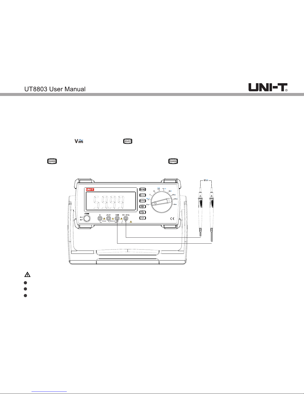
1. DC voltage measurement
a) Insert red test lead to V jack, black lead to COM jack.
b) Switch the dial to position, press button to enter DC measurement mode (figure 1). Connect
the test leads to the load in parallel.
c) Reading displayed.
d) Press button to manually switch the range. Press 4 times to enter mV range.
Note:
Do not input voltage over 1000V, or it may pose shock hazard.
Use caution to measure high voltage
After each measurement, disconnect test leads and circuit being measured.
黑
红
L
DIGITAL MULTIMETER
True RMS
6000 Counts
FUSED
CAT II 600V
FUSED
MAX 30 sec EACH 15min
1000V
750V max
Table of contents
Other Unit Multimeter manuals


Popular Multimeter manuals by other brands


Gossen MetraWatt
Gossen MetraWatt METRAmax 6 operating instructions

PeakTech
PeakTech 4000 Procedure of calibration

YOKOGAWA
YOKOGAWA 90050B user manual

Gossen MetraWatt
Gossen MetraWatt METRALINE DMM16 operating instructions

Fluke
Fluke 8846A Programmer's manual

Tempo Communications
Tempo Communications MM200 instruction manual


