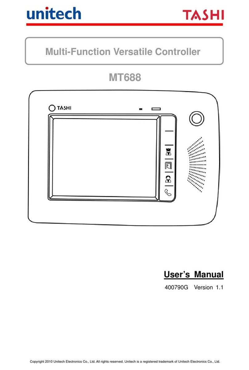
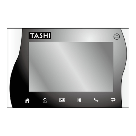
Unitech Tashi MT688 User manual

Copyright 2009 Unitech Electronics Co., Ltd.
All rights reserved. Unitech is a registered trademark of Unitech Electronics Co., Ltd.
Multi-Function Versatile Controller
MT688
Quick Reference Guide
400791G Version 1.0
Multi-Function Versatile Controller

Copyright 2009 Unitech Electronics Co., Ltd.
All rights reserved. Unitech is a registered trademark of Unitech Electronics Co., Ltd.

Copyright 2010 Unitech Electronics Co., Ltd.
All rights reserved. Unitech is a registered trademark of Unitech Electronics Co., Ltd.
English Deutsch Español Français
中文(简体) 中文(繁體) 日本語 영어
Tour of the MT688
Please make sure the following contents are in the MT688 box. If anything
appears missing or damaged, please contact a Unitech representative.
MT688 Power Adapter (Optional)
Terminal Block Plug (2) QRG paper note
NOTE: The MT688’s display ships with two transparent protection films. It is
not recommended to remove the second lower film, because the
screen will be more susceptible to scratching without it. The screen is
more legible without the film.
If your MT688 is provided with RFID reader, you will see the RFID
reader logo on the front panel of MT688.

Copyright 2009 Unitech Electronics Co., Ltd.
All rights reserved. Unitech is a registered trademark of Unitech Electronics Co., Ltd.
English Deutsch Español Français
中文(简体) 中文(繁體) 日本語 영어
The following sections describe the main components and features of the
MT688.
Front Panel
Connecting Power
Connect power to the MT688 through the following instruction:
Plug the Power Adapter Cable into the MT688’s DC input jack and then
connect the other end of the Power Adapter into an electrical outlet.
Emergency Button
Speaker
Function Buttons
Power LED
Microphone
2.0 Megapixel
CMOS Camera
RS232/485 Switch (for Port) RS232/485 Switch (for Terminal Block)
Ethernet Por
t
RS232/485 Por
t
DC Input Jack
Telephone Jack
USB Port (Client)
USB Port (Host)

Copyright 2010 Unitech Electronics Co., Ltd.
All rights reserved. Unitech is a registered trademark of Unitech Electronics Co., Ltd.
English Deutsch Español Français
中文(简体) 中文(繁體) 日本語 영어
Powering On the MT688
The MT688 automatically powers on when the Power Adapter plugs into an
external power source. The MT688 welcome screen appears, followed by the
Windows CE screen.
Using the Touch-screen
1. Tap the screen to choose a menu option.
2. Double tap to open programs.
3. Use the Windows CE Keyboard to type letters or numbers into a data field
or on a form.
Calibrating the Screen
The calibration screen automatically appears when the MT688 is powered ON
for the first time or when the system is reset.
Tap a sequence of target marks across the screen. Tap gently, but firmly by
touching the screen.
The Date/Time properties screen will appear after the screen calibration has
been confirmed.
Setting the Date and Time
In the Date/Time Properties window, touch the screen to select the current
date/time, time zone and daylight saving time option.
Tap the Left or Right arrows to scroll through the desired year and month,
or directly tap the year or month to change the setting.
Tap on the Hr/Min/Sec AM/PM to input the Hr/Min/Sec to set the time.

Copyright 2009 Unitech Electronics Co., Ltd.
All rights reserved. Unitech is a registered trademark of Unitech Electronics Co., Ltd.
English Deutsch Español Français
中文(简体) 中文(繁體) 日本語 영어
Tap the arrow and set the correct time zone from the drop-down menu.
Check the box to enable Windows to automatically adjust for day-light
saving time.
Tap Apply to save the settings and exit the Date/Time Properties dialog, or
tap to exit without saving.
Using the Terminal Block
The MT688 provides two 12-position terminal blocks for input/output signals.
Insert the wire’s stripped end into the desired terminal block position. Tighten
the lock screw to secure the wire.
Terminal Block Pin Assignment
J2 Terminal Block Port
Pin Name Description Pin Name Description
1 D1+ Photo-IN Anode (+) 7 D4+ Photo-IN Anode (+)
2 D1- Photo-IN Cathode (-) 8 D4- Photo-IN Cathode (-)
3 D2+ Photo-IN Anode (+) 9 PLC TX PLC TX
4 D2- Photo-IN Cathode (-) 10 PLC RX PLC RX
5 D3+ Photo-IN Anode (+) 11 12V External DC 12V input
6 D3- Photo-IN Cathode (-) 12 GND GND
Date Setting
Time Setting
Time Zone Setting
Daylight Saving

Copyright 2010 Unitech Electronics Co., Ltd.
All rights reserved. Unitech is a registered trademark of Unitech Electronics Co., Ltd.
English Deutsch Español Français
中文(简体) 中文(繁體) 日本語 영어
J3 Terminal Block Port
Pin Name Description
1 R1-C Relay 1 Common
2 R1-NO Relay 1 Normal Open
3 R1-NC Relay 1 Normal Close
4 R2-C Relay 2 Common
5 R2-NO Relay 2 Normal Open
6 R2-NC Relay 2 Normal Close
7 R3-C Relay 3 Common
8 R3-NO Relay 3 Normal Open
9 R3-NC Relay 3 Normal Close
10 R4-C Relay 4 Common
11 R4-NO Relay 4 Normal Open
12 R4-NC Relay 4 Normal Close
Relay Output
RL1-CTRL →High R1 (C & NO Linked)
RL1-CTRL →Low R1 (C & NC Linked)
RL2-CTRL →High R2 (C & NO Linked)
RL2-CTRL →Low R2 (C & NC Linked)
RL3-CTRL →High R3 (C & NO Linked)
RL3-CTRL →Low R3 (C & NC Linked)
RL4-CTRL →High R4 (C & NO Linked)
RL4-CTRL →Low R4 (C & NC Linked)
Digit Input
D1+ and D1- are the positive and negative nodes of the external signal inputs.
D1+ = 3V ~ 12V,
D1- = GND DIGIT-INPUT1 = High
D1+ = 0V ~ 2V,
D1- = GND DIGIT-INPUT1 = Low
D2+ and D2- are the positive and negative nodes of the external signal inputs.
D2+ = 3V ~ 12V,
D2- = GND DIGIT-INPUT2 = High
D2+ = 0V ~ 2V,
D2- = GND DIGIT-INPUT2 = Low

Copyright 2009 Unitech Electronics Co., Ltd.
All rights reserved. Unitech is a registered trademark of Unitech Electronics Co., Ltd.
English Deutsch Español Français
中文(简体) 中文(繁體) 日本語 영어
D3+ and D3- are the positive and negative nodes of the external signal inputs.
D3+ = 3V ~ 12V,
D3- = GND DIGIT-INPUT3 = High
D3+ = 0V ~ 2V,
D3- = GND DIGIT-INPUT3 = Low
D4+ and D4- are the positive and negative nodes of the external signal inputs.
D4+ = 3V ~ 12V,
D4- = GND DIGIT-INPUT4 = High
D4+ = 0V ~ 2V,
D4- = GND DIGIT-INPUT4 = Low

Copyright 2010 Unitech Electronics Co., Ltd.
Alle Rechte vorbehalten. Unitech ist eine eingetragenes Markenzeichen von Unitech Electronics Co., Ltd.
English Deutsch Español Français
中文(简体) 中文(繁體) 日本語 영어
MT688 Beschreibung
Bitte kontrollieren Sie, dass die folgenden Inhalte im MT688 Paket enthalten
sind. Wenn ein Bestandteil fehlt oder beschädigt sein sollte, kontaktieren Sie
bitte einen Vertreter von Unitech.
MT688 Netzteil (Optional)
Anschlussblockstecker (2) Kurzanleitungshinweis
HINWEIS: Der Bildschirm des MT688 wird mit zwei transparenten
Schutzfolien ausgeliefert. Wir empfehlen Ihnen, die zweite untere
Folie nicht zu entfernen, da der Bildschirm ohne diese Folie
anfälliger für Kratzer ist. Er ist jedoch ohne die Folie besser lesbar.
Falls Ihr MT688 mit einem RFID-Lesegerät ausgestattet ist,
werden Sie das RFID-Leserlogo an der Vorderseite des
MT688 sehen.
Multifunktions-Controller

Copyright 2010 Unitech Electronics Co., Ltd.
Alle Rechte vorbehalten. Unitech ist eine eingetragenes Markenzeichen von Unitech Electronics Co., Ltd.
English Deutsch Español Français
中文(简体) 中文(繁體) 日本語 영어
Die folgenden Abschnitte beschreiben die Hauptkomponenten und Funktionen
von MT688.
Vorderseite
Stromversorgung
So schließen Sie den MT688 an die Stromversorgung an:
Stecken Sie das Netzteilkabel in die DC-Eingangsbuchse des MT688 und das
andere Ende des Netzteils in die Steckdose.
Notruftaste
Lautsprecher
Funktionstasten
Strom-LED
Mikrofon
2,0 Megapixel
CMOS Kamera
RS232/485 Schalter (für Port) RS232/485 Schalter (für Anschlussblock)
Ethernet Por
t
RS232/485 Por
t
DC Eingangsbuchse
Telefonbuchse
USB Port (Client)
USB Port (Host)

Copyright 2010 Unitech Electronics Co., Ltd.
Alle Rechte vorbehalten. Unitech ist eine eingetragenes Markenzeichen von Unitech Electronics Co., Ltd.
English Deutsch Español Français
中文(简体) 中文(繁體) 日本語 영어
Einschalten des MT688
Der MT688 schaltet sich automatisch ein, wenn das Netzteil an eine externe
Stromquelle angeschlossen wird. Der Begrüßungsbildschirm des MT688
erscheint, gefolgt vom Windows CE-Bildschirm.
Verwenden des Touchscreens
1. Tippen Sie auf den Bildschirm, um eine Menüoption auszuwählen.
2. Tippen Sie doppelt, um Programme zu öffnen.
3. Verwenden Sie die Windows CE-Tastatur, um Buchstaben oder Zahlen in
ein Datenfeld oder ein Formular einzugeben.
Kalibrieren des Bildschirms
Die Kalibrierungsanzeige erscheint automatisch, wenn der MT688 das erste
Mal eingeschaltet wird oder nachdem das System zurückgesetzt wurde.
Tippen Sie auf eine Folge von Zielmarkierungen, die über den Bildschirm
verteilt sind. Tippen Sie mit sanfter, aber dennoch bestimmter Berührung auf
den Bildschirm.
Die Bildschirmanzeige mit den Datums-/Zeiteinstellungen erscheint, sobald die
Bildschirmkalibrierung abgeschlossen ist.
Einstellen von Datum und Uhrzeit
Berühren Sie im Fenster für die Datums-/Zeiteinstellungen den Bildschirm, um
das aktuelle Datum und die Uhrzeit auszuwählen, ebenso wie die Zeitzone
und die Option für die Sommerzeit.
Tippen Sie auf den linken oder rechten Pfeil, um zum gewünschten Jahr
oder Monat weiterzublättern, oder tippen Sie das Jahr und den Monat
direkt an, um die Einstellung zu ändern.
Tippen Sie auf Std/Min/Sek AM/PM, um die aktuelle Std/Min/Sek
einzugeben.

Copyright 2010 Unitech Electronics Co., Ltd.
Alle Rechte vorbehalten. Unitech ist eine eingetragenes Markenzeichen von Unitech Electronics Co., Ltd.
English Deutsch Español Français
中文(简体) 中文(繁體) 日本語 영어
Tippen sie auf den Pfeil und wählen Sie die richtige Zeitzone aus dem
Auswahlmenü aus.
Aktivieren Sie die Windows-Option mit dem Kästchen Automatisch für
Sommerzeit anpassen.
Tippen Sie Übernehmen, um die Einstellungen zu speichern und den
Einstellungsdialog für Datum/Uhrzeit zu verlassen. Sie können auch
antippen, ohne zu speichern.
Verwenden des Anschlussblocks
Der MT688 verfügt über zwei Anschlussblöcke mit 12 Positionen für Eingabe-
und Ausgabesignale.
Fügen Sie das abisolierte Ende des Kabels an der gewünschten
Anschlussblockposition ein. Ziehen Sie die Feststellschraube fest, um das
Kabel zu sichern.
Anschlussblock-Steckerbelegung
J2 Anschlussblock-Port
Stecker Name Beschreibung Stecker Name Beschreibung
1 D1+ Foto-EIN Anode (+) 7 D4+ Foto-EIN Anode (+)
2 D1- Foto-EIN Kathode (-) 8 D4- Foto-EIN Kathode (-)
3 D2+ Foto-EIN Anode (+) 9 PLC TX PLC TX
4 D2- Foto-EIN Kathode (-) 10 PLC RX PLC RX
5 D3+
Foto-EIN Anode (+) 11 12V Externer DC
12V-Eingang
6 D3- Foto-EIN Kathode (-) 12 GND GND
Datumseinstellung
Zeiteinstellung
Zeitzoneneinstellung
Sommerzeiteinstellung
Feststellschraube

Copyright 2010 Unitech Electronics Co., Ltd.
Alle Rechte vorbehalten. Unitech ist eine eingetragenes Markenzeichen von Unitech Electronics Co., Ltd.
English Deutsch Español Français
中文(简体) 中文(繁體) 日本語 영어
J3 Anschlussblock-Port
Stecker Name Beschreibung
1 R1-C Relais 1 Mittelkontakt
2 R1-NO Relais 1 Schließer
3 R1-NC Relais 1 Öffner
4 R2-C Relais 2 Mittelkontakt
5 R2-NO Relais 2 Schließer
6 R2-NC Relais 2 Öffner
7 R3-C Relais 3 Mittelkontakt
8 R3-NO Relais 3 Schließer
9 R3-NC Relais 3 Öffner
10 R4-C Relais 4 Mittelkontakt
11 R4-NO Relais 4 Schließer
12 R4-NC Relais 4 Öffner
Relais Ausgang
RL1-CTRL →Hoch R1 (C & NO Verbunden)
RL1-CTRL →Niedrig R1 (C & NC Verbunden)
RL2-CTRL →Hoch R2 (C & NO Verbunden)
RL2-CTRL →Niedrig R2 (C & NC Verbunden)
RL3-CTRL →Hoch R3 (C & NO Verbunden)
RL3-CTRL →Niedrig R3 (C & NC Verbunden)
RL4-CTRL →Hoch R4 (C & NO Verbunden)
RL4-CTRL →Niedrig R4 (C & NC Verbunden)
Digitale Eingabe
D1+ und D1- sind die positiven und negativen Knoten für die externe
Signaleingabe.
D1+ = 3V ~ 12V,
D1- = GND
DIGITALER EINGANG1 =
Hoch
D1+ = 0V ~ 2V,
D1- = GND
DIGITALER EINGANG1 =
Niedrig
D2+ und D2- sind die positiven und negativen Knoten für die externe
Signaleingabe.
D2+ = 3V ~ 12V,
D2- = GND
DIGITALER EINGANG2 =
Hoch
D2+ = 0V ~ 2V,
D2- = GND
DIGITALER EINGANG2 =
Niedrig

Copyright 2010 Unitech Electronics Co., Ltd.
Alle Rechte vorbehalten. Unitech ist eine eingetragenes Markenzeichen von Unitech Electronics Co., Ltd.
English Deutsch Español Français
中文(简体) 中文(繁體) 日本語 영어
D3+ und D3- sind die positiven und negativen Knoten für die externe
Signaleingabe.
D3+ = 3V ~ 12V,
D3- = GND
DIGITALER EING
A
NG3 =
Hoch
D3+ = 0V ~ 2V,
D3- = GND
DIGITALER EINGANG3 =
Niedrig
D4+ und D4- sind die positiven und negativen Knoten für die externe
Signaleingabe.
D4+ = 3V ~ 12V,
D4- = GND
DIGITALER EINGANG4 =
Hoch
D4+ = 0V ~ 2V,
D4- = GND
DIGITALER EINGANG4 =
Niedrig

Copyright 2010 Unitech Electronics Co., Ltd.
Todos los derechos reservados. Unitech es una marca registrada de Unitech Electronics Co., Ltd.
English Deutsch Español Français 中文(简体) 中文(繁體) 日本語 영어
Vista General de la MT688
Asegúrese de que los siguientes elementos se encuentran en la caja MT688.
Si algo no se encuentra o está dañado, póngase en contacto con un
representante de Unitech.
MT688 Adaptador de Corriente (Opcional)
Enchufe de Bloque de Terminal (2) Nota Papel QRG
NOTA: La pantalla del MT688 se envía con dos films protectores
transparentes. No se recomienda quitar la segunda capa porque la
pantalla será más susceptible de sufrir arañazos. La pantalla es más
legible con el film.
Si su MT688 incorpora lector RFID, verá el logo en el panel frontal
del MT688.
Controladora Versatil Multifunción

Copyright 2010 Unitech Electronics Co., Ltd.
Todos los derechos reservados. Unitech es una marca registrada de Unitech Electronics Co., Ltd.
English Deutsch Español Français 中文(简体) 中文(繁體) 日本語 영어
Las siguientes secciones describen los principales componentes y
características de la MT688.
Panel Frontal
Conexión a la fuente de alimentación
Conecte el MT688 a la corriente mediante las siguientes instrucciones:
Conecte el Cable Adaptador de Corriente a la clavija de entrada DC del MT688 y
conecte el otro extremo del Adaptador de Corriente a una salida eléctrica.
Botón de
Emergencia
Altavoces
Botones de Función
Power LED
Micrófono
Cámara CMOS de
2,0 Megapíxeles
Interruptor RS232/485 (para puerto) Interruptor RS232/485 (Para bloque terminal)
Puerto Ethernet
Puerto RS232/485
Conexión de la entrada CC
Conexión del teléfono
Puerto USB (Cliente)
Puerto USB (Host)

Copyright 2010 Unitech Electronics Co., Ltd.
Todos los derechos reservados. Unitech es una marca registrada de Unitech Electronics Co., Ltd.
English Deutsch Español Français 中文(简体) 中文(繁體) 日本語 영어
Encendiendo el MT688
El MT688 se enciende automáticamente cuando el Adaptador de Corriente se
conecta a una fuente de corriente externa. Aparece la pantalla de bienvenida
del MT688, seguida de la pantalla de Windows CE.
Usando la pantalla Táctil
1. Pulse la pantalla para seleccionar una opción del menú.
2. Pulse dos veces para abrir los programas.
3. Use el teclado Windows CE para escribir letras o números en un campo
de datos o en un formulario.
Calibrando la Pantalla
La pantalla de calibración aparece automáticamente cuando el MT688 se
enciente por primera vez o cuando el sistema se resetea.
Pulse la secuencia de marcas en la pantalla. Pulse con cuidado, pero tocando
firmemente la pantalla.
Las propiedades de pantalla Fecha/Hora aparecen cuando se haya
confirmado la calibración de la pantalla.
Configurando la Fecha y Hora
En la ventana de Propiedades de Fecha y Hora, pulse la pantalla para
seleccionar la fecha/hora actual, la zona horaria y la opción de ahorro diurno.
Pulse las flechas izquierda o derecha para moverse a través del año y
mes deseado o directamente introduzca el año o el mes para cambiar la
configuración.
Pulse en Hr/Min/Seg AM/PM para introducir Hr/Min/Seg para configurar la
hora.

Copyright 2010 Unitech Electronics Co., Ltd.
Todos los derechos reservados. Unitech es una marca registrada de Unitech Electronics Co., Ltd.
English Deutsch Español Français 中文(简体) 中文(繁體) 日本語 영어
Pulse la flecha.para seleccionar la zona horaria correcta del menú
desplegable.
Seleccione la casilla para habilitar que Windows ajustes automáticamente
el ahorro de energía diurno.
Pulse Aplicar para guardar los ajustes y salir del diálogo Propiedades de
Fecha/Hora o pulse para salir sin guardar.
Usando el Bloque del Terminal
El MT688 tiene dos bloques de terminal de 12 posiciones para señales de
entrada/salida.
Inserte el extremo el cable en la posición deseada del bloque del terminal.
Tense el tornillo de cierre para asegurar el cable.
Asignación del Pin del Bloque del Terminal
J2 Puerto del Bloque del Terminal
Pin Nombre Descripción Pin Nombre Descripción
1 D1+ Photo-IN Ánodo (+) 7 D4+ Photo-IN Ánodo (+)
2 D1- Photo-IN Cátodo (-) 8 D4- Photo-IN Cátodo (-)
3 D2+ Photo-IN Ánodo (+) 9 PLC TX PLC TX
4 D2- Photo-IN Cátodo (-) 10 PLC RX PLC RX
5 D3+ Photo-IN Ánodo (+) 11 12V Entrada externa DC 12V
6 D3- Photo-IN Cátodo (-) 12 GND GND
Configuración de Fecha
Configuración de Hora
Configuración de
Zona Horaria
Ahorro Diurno
Tornillo de Cierre

Copyright 2010 Unitech Electronics Co., Ltd.
Todos los derechos reservados. Unitech es una marca registrada de Unitech Electronics Co., Ltd.
English Deutsch Español Français 中文(简体) 中文(繁體) 日本語 영어
J3 Puerto del Bloque del Terminal
Pin Nombre Descripción
1 R1-C Transmisión 1 Común
2 R1-NO Transmisión 1 Normal Abierta
3 R1-NC Transmisión 1 Normal Cerrada
4 R2-C Transmisión 2 Común
5 R2-NO Transmisión 2 Normal Abierta
6 R2-NC Transmisión 2 Normal Cerrada
7 R3-C Transmisión 3 Común
8 R3-NO Transmisión 3 Normal Abierta
9 R3-NC Transmisión 3 Normal Cerrada
10 R4-C Transmisión 4 Común
11 R4-NO Transmisión 4 Normal Abierta
12 R4-NC Transmisión 4 Normal Cerrada
Salida de Transmisión
RL1-CTRL →Alta R1 (C & NO Conectada)
RL1-CTRL →Baja R1 (C & NC Conectada)
RL2-CTRL →Alta R2 (C & NO Conectada)
RL2-CTRL →Baja R2 (C & NC Conectada)
RL3-CTRL →Alta R3 (C & NO Conectada)
RL3-CTRL →Baja R3 (C & NC Conectada)
RL4-CTRL →Alta R4 (C & NO Conectada)
RL4-CTRL →Baja R4 (C & NC Conectada)
Entrada de Dígito
D1+ y D1- son los ánodos positivos y negativos en las entradas externas de
señal.
D1+ = 3V ~ 12V,
D1- = GND
ENTRADA DE DÍGITO1 =
Alta
D1+ = 0V ~ 2V,
D1- = GND
ENTRADA DE DÍGITO1 =
Baja
D2+ y D2- son los ánodos positivos y negativos en las entradas externas de
señal.
D2+ = 3V ~ 12V,
D2- = GND
ENTRADA DE DÍGITO2 =
Alta
D2+ = 0V ~ 2V,
D2- = GND
ENTRADA DE DÍGITO2 =
Baja

Copyright 2010 Unitech Electronics Co., Ltd.
Todos los derechos reservados. Unitech es una marca registrada de Unitech Electronics Co., Ltd.
English Deutsch Español Français 中文(简体) 中文(繁體) 日本語 영어
D3+ y D3- son los ánodos positivos y negativos en las entradas externas de
señal.
D3+ = 3V ~ 12V,
D3- = GND
ENTRADA DE DÍGITO3 =
Alta
D3+ = 0V ~ 2V,
D3- = GND
ENTRADA DE DÍGITO3 =
Baja
D4+ y D4- son los ánodos positivos y negativos en las entradas externas de
señal.
D4+ = 3V ~ 12V,
D4- = GND
ENTRADA DE DÍGITO4 =
Alta
D4+ = 0V ~ 2V,
D4- = GND
ENTRADA DE DÍGITO4 =
Baja
Other manuals for Tashi MT688
1
Table of contents
Languages:
Other Unitech Controllers manuals
Popular Controllers manuals by other brands

Calpeda
Calpeda IDROMAT 5 Original operating instructions

vacuubrand
vacuubrand VACUU-SELECT Instructions for use
Holmes Hobbies
Holmes Hobbies TorqueMaster BR-XL user guide

LAUREL Electronics
LAUREL Electronics MAGNA RS485 Installation & operating manual
Fisher
Fisher 4194B Series instruction manual

Fermax
Fermax 8053 manual
