Unitech UT-201 User manual

@
+91 7046223333 , 9427301436
www.utplindia.in
www
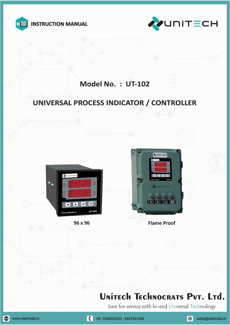
Model No. : UT-201
DUAL CHANNEL UNIVERSAL
PROCESS INDICATOR / CONTROLLER
INSTRUCTION MANUAL
M
96 x 96 Flame Proof
UT-201
M
COM
www.utplindia.in
RL-2
RL-1
RL-4
RL-3
201.0
201.0
UT-201
M
COM
www.utplindia.in
RL-2
RL-1
RL-4
RL-3
201.1
201.2

@
+91 7046223333 , 9427301436
www.utplindia.in
www
UT-201 UNIVERSAL PROCESS INDICATOR & CONTROLLER
I
WARNING
Electrical Consideration / Precautions
The controller is considered “Rack and panel mounted equipment” per EN 61010-1, Safety Requirements for
electrical equipment for Measurement, Control and Laboratory Use, Part 1: General Requirements. Conformity
with 2/23/EEC Low Voltage Directive, requires the user to provide adequate protection against a shock hazard.
The user shall install this controller in an enclosure that prevents OPERATOR access to the rear terminals.
FAILURE TO COMPLY WITH THESE INSTRUCTIONS COULD RESULT IN DEATH OR SERIOUS INJURY.
Shielded twisted pair cable is required for all Analog Input & Output, Process Variables,
RTD, Thermocouple, DC volts-mV, low level signal, mA, Alarm Outputs, and Computer
communication interface circuits.
CAUTION
FAILURE TO COMPLY WITH THESE INSTRUCTIONS MAY RESULT IN PRODUCT DAMAGE.
Power Supply / Wiring Requirements
Applying 240V AC to a controller rated for 12-24VDC will severely damage the controller
and is a fire and smoke hazard.
This controller is suitable for connection to 230 + 15% VAC, 50 Hz or 12 / 24 VDC, power mains.
It is the user responsibility to provide the following
230 + 15% VAC - a switch, fuse (1/2A, 250V) or a circuit breaker.
12 / 24 VDC – a switch, fuse (1A, 125A) or a circuit breaker.
The above items should be installed together with UT-201 for the products electrical protection.
The switch, Fuse or circuit-breaker should be located close to the controller, within easy reach
operator. The switch or Circuit-breaker should be marked as the disconnecting device for the
controller. applying power to Multiple instruments, make sure that sufficient current is supplied,
Otherwise, the instruments may not start up normally due to the voltage drop caused by the in-
rush current.
FAILURE TO COMPLY WITH THESE INSTRUCTIONS MAY RESULT IN PRODUCT DAMAGE.
Disposal action of Instruments follows as per country and regional law and rules & regulation also same in
international. Company might be follows as per rules.
DISPOSAL ACTION
PRE CAUTIONS, WARNING AND DISPOSAL ACTION
Line voltage Wiring

@
+91 7046223333 , 9427301436
www.utplindia.in
www
UT-201 UNIVERSAL PROCESS INDICATOR & CONTROLLER
1
CONTENTS
2. INSTALLATION
2.1 MOUNTING
2.2 EXTERNAL DIMENSION
2.3 TECHNICAL SPECIFICATIONS
2.4 WIRING DIAGRAM
3. PROGRAMMING
3.1 OPERATION INTERFACE
3.2 MODE ACCESS FLOW CHART
4.1 CONFIGURATION MODE
4. OPERATIONAL MODES
4.2 SETUP MODE
4.3 CALIBRATION MODE
4.4 CHANGE PASSWORD MODE
4.5 ERROR MESSAGE.
5. COMMUNICATION [MODBUS RTU] PROTOCOL
5.1 INTRODUCTION
5.2 MODBUS CONFIGURATION BASIC SETTINGS
5.3 REGISTER ADDRESSES FOR MODBUS / RTU PROTOCOL
1. OVERVIEW
1.1 INTRODUCTION
2
2
2
2
2
3
4
5
5
6
7
7
9
10
11
11
12
12
12
12
12
5.4 MODBUS SYSTEM SCHEMATIC.
...................................................................................................
.........................................................................................
...................................................................................................
...................................................................................................
...................................................................................................
...................................................................................................
...................................................................................................
...........................................................................................
.............................................................................
....................................................................
...................................................................................
...........................................................................
............................................................................................
.................................................................................
.....................................................................
......................................................................................
...............................................
.........................................................................................
.............................................
...................................
.....................................................................

@
+91 7046223333 , 9427301436
www.utplindia.in
www
UT-201 UNIVERSAL PROCESS INDICATOR & CONTROLLER
2
1.1 Introduction
Function
Mount Anywhere
The instrument can be configured for RTD or Thermocouple or Linear input by making changes in
configuration mode using 4 keys provided. This instrument can operate with full range for all inputs.
Unitech’s UT-201 Dual Channel Universal Indicator is designed to accept 2 Nos. thermocouple or RTD or
Linear Input and displays the process parameter through a dual set of 4 Digit Red LED Displays.
The instrument is available in a panel mounted housing which requires a cut out as per Panel cutout Dime-
- nsions given later . A variety of power supply options are available for this. The instrument has low drift
precision components for long trouble free operation. The instrument is a jumper less system. There are
different types of modes such as normal mode, operation mode, configuration mode, setup mode, and
change password mode. 4 keys provided can do any change in the mode.
Two different configuration levels provide easy access to parameters. A4 digit security code perverts una-
uthorized changes. Parameters can also be hidden to user to prevent improper configuration of the unit
The UT-201 product group is Process control instruments that must be panel mounted. The wiring terminals
must be provided. the UT-201 is environmentally hardened and, if suitably handled, can be mounted virtua-
-lly anywhere in plant or factory; in a panel or enclosure wall mounted or Flameproof enclosure or even on
the process machinery. it can withstand ambient temperature up to 50°C
Easy to Configure
1. OVERVIEW
2.1 Mounting
2.2 External Dimension
2. INSTALLATION
CAUTION
The product can be mounted on tilted or horizontal
panel using the mounting clamps supplied. Proper
space must be available at the back of the panel for
installation and maintenance activity.
Installation Mounting Precautions
FAILURE TO COMPLY WITH THESE INSTRUCTION MAY
RESULT IN INSTRUMENT DAMAGE
Side View
DIMENSION
Model A B D
CE
UT - 201
96 90
10 120
90+0.5
96 90+0.5 120
100
All dimensions are in mm
8.8.8.8.
100.0
UT-201
M
COM
www.utplindia.in
RL-2
RL-1
RL-4
RL-3
8.8.8.8.
100.0

@
+91 7046223333 , 9427301436
www.utplindia.in
www
UT-201 UNIVERSAL PROCESS INDICATOR & CONTROLLER
3
Flame Proof
K : -50~1200˚C
R : 0~1750˚C
T : 0~400˚C
INPUT
RANGE
High scale / Low scale Full range as per input selection
General
Specificaion
Power Supply 110/240V AC, 50Hz, 12/24VDC [Optional on demand]
Power Consumption 4 Watts Maximum
Operating Ambient Temp. : 0~50˚C, Humidity : Below 90% Non condensing
Input
T/C K, J, R, S, T, E
RTD Pt-100, Pt-1000, Cu-53 [2 wire, 3 wire]
Linear : 4 ~20mA DC, 0~20mA DC, 0 ~5 Amp AC
CURRENT [Analog]
VOLTAGE [Analog]
Linear : 0.5~2.5VDC, 1~5VDC, 0~10VDC
SPECIAL ON DEMAND
Linear : 0~75m/0~200mVDC, 0~100/200/300VDC
Indication
Display Indication [Ch:1] : 0.56” 4 Digit [Ch:2]: 0.56” 4 Digit, 2 set 7 Segment Red Displays.
Relay Status Front Red LED for all Relay Alarm status
RTD Pt-100 : -50~400˚C
Linear All DC & AC : -1999~9999 Display
CURRENT [Analog]
VOLTAGE [Analog]
Linear All DC : -1999~9999 Display
SPECIAL ON DEMAND
Linear : -1999~9999 Display
T/C
Accuracy
T/C + 0.25% of Full Scale
RTD Class A
+ 0.1% of Full Scale
ANALOG [V & I]
SPECIAL ON DEMAND
+ 0.1% of Full Scale
Automatic Software based self compensation
Cold Junction Comp.
“OPEN” or “OVER” indication on display
Sensor Break Info.
AS per Input Range Table
Range Limits
>330 K for Voltage ,mV, and T/C, 100 R for current
Input Impedance
Status indication
Alarm modes
LEDs for Relay status & Communication
Low / High
Control Mode On Off control
Dead Band controls High and Low Set point for level application
Relay / SSR Max. : 2 Nos.[one for each channel]
Relay Output
SSR [Volt] Output
Retransmission
24VDC @ 20 mA ,12VDC @ 20 mA
Linear : 0~20/ 4~20 mA DC, 0~10 VDC
NO-C-NC Contacts , 5A@240 VAC Resistive, 2 Relays for each input
Other Output
Transmitter Power Supply : Isolated 24VDC@60mA ,Max.
Output
Prog. parameters
Modbus RTU RS- 485/RS- 232 Communication
Baud rate, Parity, Node address, Stop bit
Protocols & method
Max. Connections
Communication
Up to 128 Units
Programmable
Parameters
Display resolution
Setpoint / Hysteresis
Relay logic
Full range as per input selection
-1999 to 9999 fully configurable for each linear input
F.S. high & low alarm
Enclosure [If Reqd.] FC-1 [1-Compartment] OR FC-2 [2-Comp.] : IIA, IIB Exter. keys & Cable Entries
TECHNICAL SPECIFICATIONS
INPUT RANGE
J : -50~750˚C,
S : 0~1750˚C,
E : -50~400˚C,
2.3 Technical Specifications
Type of Input
[Ch-1 & Ch-2]

@
+91 7046223333 , 9427301436
www.utplindia.in
www
UT-201 UNIVERSAL PROCESS INDICATOR & CONTROLLER
4
CAUTION
WIRING CONSIDERATION
Shielded twisted pair wire is used for all analog I/P, Process sensors RTD,
Thermo-couple, mV-mA DC, Volt DC, Linear input and Communication.
FAILURE TO COMPLY WITH THESE INSTRUCTION MAY RESULT
IN INSTRUMENT DAMAGE
CAUTION
LINE VOLTAGE
This product is suitable for connection 110/230VAC, 50Hz or 12/24 VDC main power
supply. It is user responsibility to provide proper protection for the products electrical
protection .
when applying power to various instruments, make sure sufficient current is supplied.
otherwise the instruments may not start up due to the Voltage drop.
FAILURE TO COMPLY WITH THESE INSTRUCTION MAY RESULT
IN INSTRUMENT DAMAGE
J / K / R / S / T / E
+
-
Shorng
19 20 21
-
THERMO-
COUPLE
B
RTD
PT-100 / 1000
19 20 21
BA
4 20mA / 0 20mA
~~
CURRENT[mA]
22 21
0 VDC5 /10
~
V
VOLTAGE
21
22
23
3 WIRE
21 22 98
T
mA Input TPS 24VDC
Transmier
TRANSMITTER
2 WIRE
21 22 98
T
mA Input TPS 24VDC
Transmier
TRANSMITTER
OUTPUT - RELAY, SSR
24VDC@20mA
12VDC@20mA
SSR-1
14 13
17 16
SSR-2
R-2
R-1
Relay Contact :
5A@240VAC
NC
C
NO
15 14 13
18 17 16
2.4 Wiring Diagram
RTD
VDC
21
20
19
24
25
D+
RS - 485
D-
NC
RELAY-2
NO CNC
NO C
RELAY-1
123456789
10
11
121314
A
B
B
TPS
24VDC
v
SUPPLY
E P
UT-201
15161718
N
T/C
mA
Noise
Filter
POWER
L
AC 230V, 50Hz
N
NOTE : 12VDC OR 24VDC SUPPLY CONTROLLERS ARE ALSO AVAILABLE ON DEMAND.
B
RTD
PT-100 / 1000
345
BA
J / K / R / S / T / E
+
-
Shorng
345
-
3 WIRE
5698
T
mA Input TPS 24VDC
Transmier
TRANSMITTER
2 WIRE
5698
T
mA Input TPS 24VDC
Transmier
TRANSMITTER
4 20mA / 0 20mA
~~
CURRENT[mA]
65
0 VDC5 /10
~
V
VOLTAGE
5
6
7
THERMO-
COUPLE
CH:1 INPUT
COMMUNICATION
RS-485
22 23
COMMNICATION
D+ D-
SUPPLY
230+15VAC
10 11
AC SUPPLY
P N
12
E
24 / 12 VDC
DC SUPPLY
10 11
22
23
230VAC
12/24VDC
N/A N/A
RTD
VDC
A
B
B
v
T/C
mA
CH:1 INPUT
CH:2 INPUT
CH:2 INPUT

@
+91 7046223333 , 9427301436
www.utplindia.in
www
UT-201 UNIVERSAL PROCESS INDICATOR & CONTROLLER
5
4 Digit 7 segment dedicated to display the Ch:1 Present value. In the
Programing mode it shows Parameter.
RL-1 LED It indicates the status of Relay-1, When LED is On, Relay is Off and When
LED if Off, Relay is On.
RL-2 LED It indicates the status of Relay-2, When LED is On, Relay is Off and When
LED if Off, Relay is On.
COM LED It indicates the active Communication between devices. When LED is Blink,
the communication is active.
KEYS
MODE KEY Press MODE or Function key to access the programming group or
parameters. press this key to return to the normal view.
NORMAL VIEWS
ENTER KEY ENTER Key allows enter into the Parameter, moving from one parameter
to another or saving a new value of parameter or a status of parameter.
Press to change set points in normal view.
UP KEY UP Key allows increasing the value of a digit selected or changing the
status of parameter in programming mode. Press to change set points in
normal view
PASS KEY PASS Key allows pass the digit of a value from right to left of a selected
parameter in programming mode. In some Parameter it also change or
decrease the value.
3. PROGRAMMING
3.1 Operation Interface
FRONT VIEW
Channel:1 Present
value Display
4 Digit 7 segment dedicated to display the Ch:2 Present value. In the
Programing mode it shows Value of Parameter.
UT-201
M
COM
www.utplindia.in
RL-2
RL-1
8.8.8.8.
201.1
PASS Key
CH:1 PV
Display
UP Key
MODE Key
ENTER Key
Relay-1 LED
COM LED
Relay-2 LED
CH:2 PV
Display
8.8.8.8.
2 0 1.2
Channel:2 Present
value Display

@
+91 7046223333 , 9427301436
www.utplindia.in
www
UT-201 UNIVERSAL PROCESS INDICATOR & CONTROLLER
6
CPAS
oPAS
0000
nPAS
8888
0000
MODE
pass
SETP
0000
ZrC1
000.0
SPC1
100.0
SP1
030.0
HYS1
000.2
SP2
050.0
HYS2
000.2
SP3
060.0
HYS3
000.2
SP4
080.0
HYS4
000.2
MODE
pass
ZrC2
000.0
SPC2
100.0
COnf
0000
1Np1
rtd1
TSP1
L oN
TSP2
L oN
MODE
pass
DP1
0001
Ded1
no
1Np2
rtd1
TSP3
L oN
TSP4
L oN
DP2
0001
BAUD
9600
PRTy
NoNE
NADD
0001
Ded2
no
WARNING
INJURY
Programming parameter should be accessed only by Personnel who are
technically competent to do so. Local regulations regarding electrical &
safety must be observed.
FAILURE TO COMPLY WITH THESE INSTRUCTION COULD BE RESULT IN SERIOUS INJURY OR DEATH
*
*
*
Default Password will be 0000
Protected Parameter Password will be 1111
NOTE :
These are the whole parameter list. Parameters
can be very as per Type or Requirement by User.
*
To come out from Programming Mode to
Normal mode Press key in any step.
CALA
0032
CZR1
----
CSP1
----
CZR2
----
CSP2
----
LoP1
----
HoP1
----
CAL
0000
MODE
pass
LoP2
----
HoP2
----
CH:2
CH:1
3.2 Mode Access Flow Chart.
8888
8888
Normal Mode
Mode Selection
Configuration Setup
Mode Mode
Change
Password Mode
Calibration
Mode
Password Protected
*Any New Password
*
Press key to enter into the
Programming mode from
Normal mode

@
+91 7046223333 , 9427301436
www.utplindia.in
www
UT-201 UNIVERSAL PROCESS INDICATOR & CONTROLLER
7
‘Configuration Mode’ will shown by pressing key in the Normal mode..
4.1 Configuration Mode
4. OPERATIONAL MODES
: Selected
YES
: Not
no
DED1
no
CHANNEL:1 DEAD BAND
Operate Relay-1 on two set points Values :
Default Value : no
If set as YES, Only Relay-1 get operated in this
parameter, relay get active on set point 1[SP1]
value and deactivate in set point 2[SP2] value.
Used for Level Control & Fan Operation.
Increase by key, Decrease by key.
Range / Values
Parameter
pass
0000
CONFIGURATION MODE PASSWORD
Password for Config. Mode Parameters
Display
: PT-100 (RTD)
: Linear 0 - 20 mA DC
: Linear 4 - 20 mA DC
T. TC
S. TC
R. TC
J. TC
: ‘T’ Type Thermo-Couple
: ‘S’ Type Thermo-Couple
: ‘R’ Type Thermo-Couple
: ‘K’ Type Thermo-Couple
: ‘J’ Type Thermo-Couple
: Linear 0 - 10 V DC
Scroll the digit by key, Increase by key.
Range : Values between 0000 to 9999
Default Input : RtD1 , It can be change as reqd.
1nP1
rtd1
CHANNEL:1 INPUT TYPE
Selection of the applied Input.
Change the type Up by key, Down by key.
Range : Input Type is as follows:
. TC
4
RTD1
0-20
4-20
-10v
Default Value : 0000
tsp1
L on
ALARM 1 RELAY ACTION
Alarm Relay activation direction.
Values :
Default Value : L on
: No decimal (1234)
0000
: Active in High
H oN
ON
OFF PV
SV
ON
OFF PV
SV
L ON :
: Active in Low
L oN
H ON :
: One decimal (123.4)
0001
: Two decimal (12.34)
0002
: Three decimal(1.234)
0003
SV-Hyst
SV+Hyst
Change the value by key, or by key.
tsp2
L on
ALARM 2 RELAY ACTION
Alarm Relay activation direction same as AL:1
Values :
Default Value : L on
: Active in High
H oN
: Active in Low
L oN
Increase by key, Decrease by key.
dp1
0001
CHANNEL:1 DECIMAL POINT [LINEAR INPUT]
Decimal Point resolution for display value.
Values :
Default Value : 0001
NOTE : Applicable for Analog Linear input only.
Change the value by key, or by key.
: PT-100 (RTD)
: Linear 0 - 20 mA DC
: Linear 4 - 20 mA DC
T. TC
S. TC
R. TC
J. TC
: ‘T’ Type Thermo-Couple
: ‘S’ Type Thermo-Couple
: ‘R’ Type Thermo-Couple
: ‘K’ Type Thermo-Couple
: ‘J’ Type Thermo-Couple
: Linear 0 - 10 V DC
Default Input : J. TC , It can be change as reqd.
1nP2
rtd1
CHANNEL:2 INPUT TYPE
Selection of the applied Input.
Change the type Up by key, Down by key.
Range : Input Type is as follows:
. TC
4
RTD1
0-20
4-20
-10v

@
+91 7046223333 , 9427301436
www.utplindia.in
www
UT-201 UNIVERSAL PROCESS INDICATOR & CONTROLLER
8
Continue Configuration Mode
WARNING
PERSONAL INJURY :
Configuration should be performed only by personnel who are technically competent to do
so. Local Regulations regarding electrical & safety must be observed.
FAILURE TO COMPLY WITH THESE INSTRUCTIONS COULD RESULT IN DEATH OR SERIOUS INJURY.
: Selected
YES
: Not
no
DED2
no
CHANNEL:2 DEAD BAND
Operate Relay-2 on two set points Values :
Default Value : no
If set as YES, Only Relay-1 get operated in this
parameter, relay get active on set point 1[SP1]
value and deactivate in set point 2[SP2] value.
Used for Level Control & Fan Operation.
Increase by key, Decrease by key.
: No decimal (1234)
0000
: One decimal (123.4)
0001
: Two decimal (12.34)
0002
: Three decimal(1.234)
0003
Increase by key, Decrease by key.
dp2
0001
CHANNEL:2 DECIMAL POINT [LINEAR INPUT]
Decimal Point resolution for display value.
Values :
Default Value : 0001
NOTE : Applicable for Analog Linear input only.
tsp3
tsp4
ALARM 3 & 4 RELAY ACTION
Alarm Relay activation direction same as AL 1&2
Values :
Default Value : L on
: Active in High
H oN
: Active in Low
L oN
Change the value by key, or by key.
&
Range / Values
Parameter
nadd
0001
NODE ADDRESS [COMMUNICATION]
Device Address for Communication
Display
Increase the no. by key, decrease by key.
Range : Values between 0001 to 0127
Default Value : 0001
: Baud Rate 4800
4800
: Baud Rate 9600
9600
: Baud Rate 19200
19.2k
Change value by key, or by key.
baud
9600
BAUD RATE [COMMUNICATION]
Baud Rate for Communication
Values :
Default Value : 9600
NOTE : Applicable if Communication Output.
NOTE : Applicable if Communication Output.
: Even Parity
EvEn
: Odd Parity
Odd
: None Parity
none
Change value by key, or by key.
prty
none
PARITY [COMMUNICATION]
Parity check for Communication
Values :
Default Value : none
NOTE : Applicable if Communication Output.

@
+91 7046223333 , 9427301436
www.utplindia.in
www
UT-201 UNIVERSAL PROCESS INDICATOR & CONTROLLER
9
‘Setup Mode’ Mode will shown by pressing key, after Conf Mode display.
4.2 Setup Mode
sp3
sp4
Hys3
Hys4
Range / Values
Parameter
pass
0000
SETUP MODE PASSWORD
Password for Setup Mode Parameters
Display
Scroll the digit by key, Increase by key.
Range : Values between 0000 to 9999
Default Value : 0000
ZRC1
000.0
CH:1 ZERO or LOW DISPLAY VALUE [LINEAR I/P]
Display value at Low Input applied.
NOTE : Applicable for Analog Linear input only.
Scroll the digit by key, Increase by key.
Range : Values between 1999 to 9999
Default Value : 000.0
-
Scroll the digit by key, Increase by key.
Range : Values between 1999 to 9999
Default Value : 100.0
-
spC1
100.0
CH:1 SPAN or HIGH DISPLAY VALUE [LINEAR I/P]
Display value at High Input applied.
NOTE : Applicable for Analog Linear input only.
Scroll the digit by key, Increase by key.
Range : Values between 199.9 to 999.9
Default Value : 030.0
-
sp1
030.0
ALARM SET POINT # 1
Activation value for Alarm Relay-1
Scroll the digit by key, Increase by key.
Range : Values between 199.9 to 999.9
Default Value : 000.2
-
Hys1
000.2
HYSTERESIS ALARM # 1
Value Diff. between On and Off of Relay-1
Scroll the digit by key, Increase by key.
Range : Values between 199.9 to 999.9
Default Value : As per User’s set Reqd.
-
ALARM SET POINT # 3 & 4
Activation value for Alarm Relay-3 & 4
Scroll the digit by key, Increase by key.
Range : Values between 199.9 to 999.9
Default Value : 000.2
-
HYSTERESIS ALARM # 3 & 4
Value Diff. between On and Off of Relay-3 & 4
(According to Decimal point)
(According to Decimal point)
(According to Decimal point)
(According to Decimal point)
(According to Decimal point)
(According to Decimal point)
HYS2
sp2
Scroll the digit by key, Increase by key.
Range : Values between 199.9 to 999.9
Default Value : As per User’s set Reqd.
-
ALARM SET POINT & HYSTERESIS # 2
Activation value & Hysteresis for Alarm Relay-2
(According to Decimal point)
&
ZRC2
000.0
CH:2 ZERO or LOW DISPLAY VALUE [LINEAR I/P]
Display value at Low Input applied.
NOTE : Applicable for Analog Linear input only.
Scroll the digit by key, Increase by key.
Range : Values between 1999 to 9999
Default Value : 000.0
-
Scroll the digit by key, Increase by key.
Range : Values between 1999 to 9999
Default Value : 100.0
-
spC2
100.0
CH:2 SPAN or HIGH DISPLAY VALUE [LINEAR I/P]
Display value at High Input applied.
NOTE : Applicable for Analog Linear input only.
(According to Decimal point)
(According to Decimal point)

@
+91 7046223333 , 9427301436
www.utplindia.in
www
UT-201 UNIVERSAL PROCESS INDICATOR & CONTROLLER
10
‘Calibration Mode’ Mode will shown by pressing key, after Setp Mode display.
4.3 Calibration Mode
0100 ~ 0600
0200 ~ 1000
0200 ~ 1000
0200 ~ 1000
0200 ~ 1000
0200 ~ 1000
7000 ~ 8000
7000 ~ 8000
7000 ~ 8000
7000 ~ 8000
7000 ~ 8000
7000 ~ 8000
INPUT
J - T/C
K - T/C
R - T/C
S - T/C
T - T/C
E - T/C
0 mV
0 mV
0 mV
ZERO VALUE
FEED VALUE COUNT
SPAN VALUE
FEED VALUE COUNT
0 mV
0 mV
0 mV
18 mV
18 mV
42 mV
42 mV
42 mV
18 mV
INPUT ZERO VALUE
FEED VALUE COUNT
SPAN VALUE
FEED VALUE COUNT
0100 ~ 0600
0100 ~ 1000
0100 ~ 1000
0100 ~ 1000
0900 ~ 1500
7000 ~ 8000
7000 ~ 8000
7000 ~ 8000
7000 ~ 8000
2000 ~ 3000
4 ~ 20mA
0 ~ 20mA
1 ~ 5 VDC
10VDC
PT-100
4 mA
0 mA
1 VDC
0 VDC
20 mA
20 mA
5 VDC
10 VDC
CALIBRATION VALUES :
0°C
[100.0Ω]
100°C
[138.51Ω]
Set Reqd. O/p by , & key, press key.
NOTE : After output cal. press key for next mode.
Hop1
Hop2
&
Range / Values
Parameter
pass
0000
CALIBRATION MODE PASSWORD
Password for Calibration Mode Parameters
Display
Scroll the digit by key, Increase by key.
Range : Values between 0000 to 9999
Default Value : 0000
zrC1
----
CALIBRATION ZERO or LOW INPUT CH:1
Calibration Zero / Low at Low / Zero PV Input.
NOTE : After Zero Cal. press key for next Para.
Apply Low signal [as per input] & press key.
Range :
Default Value : ----
According to Input Type
CSP1
----
CALIBRATION SPAN or HIGH INPUT CH:1
Calibration Span / High at Span / High PV Input.
NOTE : After Span Cal. press key for next para.
Apply High signal [as per input] & press key.
Lop1
Lop2
CALIBRATION LOW [RETRANSMISSION] OUTPUT
Calibration desired Low Output for Both Input.
NOTE : After out low cal. press key for next Para.
Set Reqd. O/p by , & key, press key.
Note : After Calibration random value
appeared in display, as per input.
Refer below Table for Cal. values range.
Note : After Calibration random value
appeared in display, as per input.
Refer below Table for Cal. values range.
Range :
Default Value : ----
According to Input Type
Note : After Cali. random value should be
below 1000 appeared in display.
Range :
Default Value : strt -> to start cal.
According to Output Type
CALIBRATION HIGH [RETRANSMISSION] OUTPUT
Calibration desired High Output at PV Display.
Range :
Default Value : strt -> to start cal.
According to Output Type
Note : After Cali. random value should be
below 8000 appeared in display.
CALa
0032
CALIBRATION AMBIENT [THERMO COUPLE INP.]
Ambient adjustment for compensation [T/C Inp.]
NOTE : After Amb. Cal. press key for exit.
Set Ambient Temp by & key,press key. Note : After Calibration random value
appeared in display, as per input.
Range :
Default Value : 0032
As per Ambient Temperature.
zrC2
----
CALIBRATION ZERO or LOW INPUT CH:2
Calibration Zero / Low same as Input-1
NOTE : After Zero Cal. press key for next Para.
Range :
Default Value : ----
According to Input Type
CSP1
----
CALIBRATION SPAN or HIGH INPUT CH:2
Calibration Span / High same as Input-1
NOTE : After Span Cal. press key for next para.
Range :
Default Value : ----
According to Input Type
&

@
+91 7046223333 , 9427301436
www.utplindia.in
www
UT-201 UNIVERSAL PROCESS INDICATOR & CONTROLLER
11
‘Change Password Mode’ Mode will shown by pressing key, after CAL Mode display.
Open the Input Connection
Sensor Break or Sensor disconnected.
Sign Description Solution
In case the following error messages appear in the display of controller,
please refer to the Error message table below, or call technical support.
OPEN Check the Input sensor wiring
Replace the sensor.
Check the Input sensor wiring
Check the Input type.
Adjust the Range
Excess of PV over the Span value
Check the Input sensor wiring
Check the Input type.
Adjust the Range
Shortage of PV over the Low value
vndr
Over
All LED’s and
display not light
No power to the controller
Controller circuit failed
Check the power connection
Check the supply voltage.
4.4 Change Password Mode
4.5 Error Message.
Range / Values
Parameter
PAsS
0000
CHANGE PASSWORD MODE PASSWORD
Password for Change Password Mode.
Display
Scroll the digit by key, Increase by key.
Range : Values between 0000 to 9999
Default Value : 0000
opas
0000
OLD EXISTING PASSWORD
Old - Default or Existing Password
Scroll the digit by key, Increase by key.
Range : Values between 0000 to 9999
Default Value : 0000
npas
8888
NEW DESIRED PASSWORD
Set new Required Desired Password
Range : Values between 0000 to 9999
Default Value : As per new required.
(Any value) Scroll the digit by key, Increase by key.
CAUTION
PASSWORD PRECAUTIONS
FAILURE TO COMPLY WITH THESE INSTRUCTION MAY RESULT IN INSTRUMENT DAMAGE
*
*
After Changing old password, all parameter are locked. All Modes are not
accessible without new password.
Changed password should be remembered , it cannot be Reset at site.

5. COMMUNICATION [MODBUS RTU] PROTOCOL
5.1 Introduction
The unit can be connected in MODBUS/RTU communication data link protocol to messaging
structure, widely used to establish master - slave communications between devices. Each
device must have unique No. node address. Before starting any communication, choose a
baud rate compatible to the host device. A Modbus data sent from a master to slave tells the
selected slave what to do and what information to send back. The MODBUS/RTU protocol
works with RS232, RS485 and RS422 standards
5.2 MODBUS Configuration Basic settings
The Basic settings for RS-485 Modbus protocol are as follows :
Band rate
Start bit
Data bit
Stop bit
Parity
9600
1
8
1
none
5.3 Register addresses for MODBUS / RTU Protocol
The addressees for RS-485 Modbus protocol are as follows :
5.4 MODBUS system schematic.
DATA+
The system schematic for RS-485 Modbus protocol are as follows :
DATA-
Ethernet
RS-232
or
RS-485
CONVERTER
D- D+
12
UT-201 Device-1
D- D+
12
D- D+
12
D- D+
12
RS-485 BUS
ADD:1 ADD:2 ADD:3 ADD:N
RS-485 BUS
Upto 128
devices
UT-201 Device-2 UT-201 Device-3 UT-201 Device-128
2 core 1 sq/mm shielded cable
www.utplindia.in
@
www
+91 7046223333 , 9427301436
All content are subject to change without notice
due to continuous improvements.
Doc. Ref. 1410/R04/0819
UNITECH TECHNOCRATS PVT LTD
FACTORY:- 78/1/Z/3-Makarpura G.I.D.C.,
N/R Vadasar Bridge. O/p-Gayatri Temple
VADODARA - 390010. Gujarat, INDIA 12
COMPUTER- SCADA
READ ONLY
SR. NO.
1 PROCESS VALUE CH : 1
PARAMETER ABSOLUTE ADDRESS ACCESS TYPE
40001
READ / WRITE
3 SET POINT-1 [SP1] 40003
READ ONLY
2 PROCESS VALUE CH : 2 40002
READ / WRITE
4 SET POINT-2 [SP2] 40004
READ ONLY
5 DECIMAL POINT : 1 40005
READ ONLY
6 DECIMAL POINT : 2 40006
READ / WRITE
7 SET POINT-3 [SP3] 40007
READ / WRITE
8 SET POINT-4 [SP4] 40008
UT-201 UNIVERSAL PROCESS INDICATOR & CONTROLLER

Table of contents
Other Unitech Controllers manuals
Popular Controllers manuals by other brands
Emerson
Emerson AVENTICS 651 Series Installation and maintenance instructions
Price
Price ECMDX Series Installation and service manual

GSI Group
GSI Group PNEG-1405 installation manual
Sundstrom
Sundstrom SR 500 Instructions for use
Gewiss
Gewiss GW96 752 Instructions for installation manual
Cytech
Cytech CP9000 Comfort II Quick installation guide
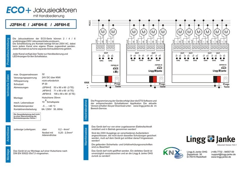
Lingg & Janke
Lingg & Janke ECO+ J2F6H-E manual
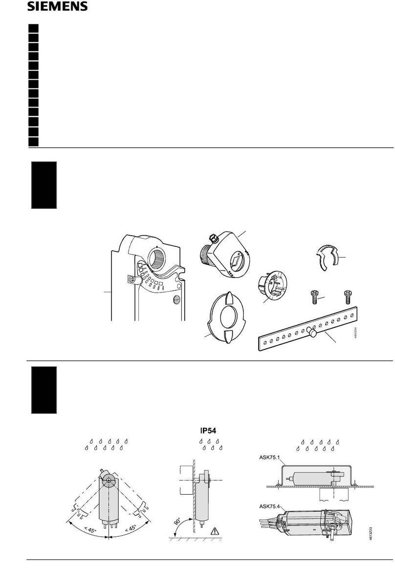
Siemens
Siemens GBB 1E Series Mounting instructions
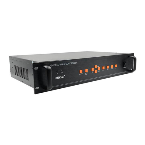
LINK-MI
LINK-MI LM-TV25 user manual

MidNite Solar
MidNite Solar Classic 150 owner's manual
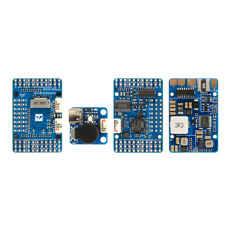
Mateksys
Mateksys F765-WSE quick start guide
Precision Digital Corporation
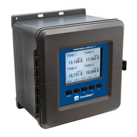
Precision Digital Corporation ConsoliDator+ instruction manual
