manuals.online logo
Brands
  1. Home
  2. •
  3. Brands
  4. •
  5. SMC Networks
  6. •
  7. Controllers
  8. •
  9. SMC Networks EQY32 User manual

SMC Networks EQY32 User manual

EQY#-TF222-152EN
Page 1 of 3
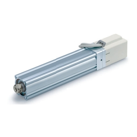
Instruction Manual
e-Actuator
/
Rod type
Easy to operate Integrated Controller
Series EQY*H*-****-B*
Motor: Step motor 24 VDC with Battery-less absolute encoder
The intended use of this Electrical Actuator is to convert an electrical
input signal into mechanical motion.
1. Safety Instructions
These safety instructions are intended to prevent hazardous situations
and/or equipment damage. These instructions indicate the level of
potential hazard with the labels of “Caution,” “Warning” or “Danger.”
They are all important notes for safety and must be followed in addition
to International Standards (ISO/IEC) *1), and other safety regulations. *1)
ISO 4414: Pneumatic fluid power - General rules relating to systems.
ISO 4413: Hydraulic fluid power - General rules relating to systems.
IEC 60204-1: Safety of machinery - Electrical equipment of machines.
(Part 1: General requirements)
ISO 10218-1: Manipulating industrial robots -Safety. Etc.
Refer to the product catalogue, Operation Manual and Handling
Precautions for SMC Products for additional information.
Keep this manual in a safe place for future reference.
Caution
Caution indicates a hazard with a low level of risk which, if
not avoided, could result in minor or moderate injury.
Warning
Warning indicates a hazard with a medium level of risk
which, if not avoided, could result in death or serious injury.
Danger
Danger indicates a hazard with a high level of risk which, if
not avoided, will result in death or serious injury.
Warning
•Always ensure compliance with relevant safety laws and standards.
All work must be carried out in a safe manner by a qualified person in
compliance with applicable national regulations.
•Electromagnetic compatibility
This product is class A equipment intended for use in an industrial
environment. There may be potential difficulties in ensuring
electromagnetic compatibility in other environments due to conducted
as well as radiated disturbances.
2. Specifications
2.1 EQY25 series
Model
EQY25
Actuator specification
Stroke [mm]
30 to 400
Max. work
load [kg] *1)
Horizontal
8
26
40
70
Vertical
2
8
16
30
Pushing Force [N] *2) *3) *4)
36~76
63~122
126~238
232~452
Speed
[mm/s]
to 300 stroke
30~900
18~700
9~450
5~225
301 to 400 stroke
30~900
18~600
9~300
5~150
Max. acceleration/
deceleration [mm/s2]
Horizontal
10,000
Vertical
5,000
Pushing speed
[mm/s
2
]
*5)
35
Positioning repeatability [mm]
±0.02
Lost motion [mm] *6)
0.1 or less
Screw Lead [mm]
20
12
6
3
Impact/Vibration resistance [m/s
2
]
*7)
50 / 20
Actuation method
Ball screw (EQY*DH)
Ball screw + Belt (EQY*H)
Guide type
Sliding bush (piston rod)
Operating temperature [°C]
5 to 40
Operating humidity [% RH]
90 or less (no condensation)
Electrical
Motor size [mm]
□42
Motor type
Battery-less absolute
(Step motor 24 VDC)
Encoder
(angular displacement sensor)
Battery-less absolute
Power supply voltage [V]
24 VDC ±10%
Max. Power [W] *8) *9)
86
Lock
Lock Type*10)
Non magnetizing lock
Holding force [N]
47
78
157
294
Power consumption [W] *9)
5
Power supply voltage [V]
24 VDC ±10%
2.2 EQY32 series
Model
EQY32
Actuator specification
Stroke [mm]
30 to 500
Max. work
load [kg] *1)
Horizontal
30
50
90
100
Vertical
3
13
26
46
Pushing Force [N] *2) *3) *4)
50~118
80~189
156~370
296~707
Speed
[mm/s]
to 300 stroke
36~900
24~800
12~400
6~200
301 to 400 stroke
36~900
24~640
12~320
6~160
450 to 500 stroke
36~900
24~640
12~320
6~160
Max. acceleration/
deceleration [mm/s2]
Horizontal
10,000
Vertical
5,000
Pushing speed
[mm/s
2
]
*5)
35
Positioning repeatability [mm]
±0.02
Lost motion [mm] *6)
0.1 or less
Screw Lead [mm]
24
16
8
4
Impact/Vibration resistance [m/s
2
]
*7)
50 / 20
Actuation method
Ball screw (EQY*DH)
Ball screw + Belt (EQY*H)
Guide type
Sliding bush (piston rod)
Operating temperature [°C]
5 to 40
Operating humidity [% RH]
90 or less (no condensation)
Electrical
Motor size [mm]
□56.4
Motor type
Battery-less absolute
(Step motor 24 VDC)
Encoder
(angular displacement sensor)
Battery-less absolute
Power supply voltage [V]
24 VDC ±10%
Max. Power [W] *8) *9)
109
Lock
Lock Type*10)
Non magnetizing lock
Holding force [N]
75
108
216
421
Power consumption [W] *9)
5
Power supply voltage [V]
24 VDC ±10%
2. Specifications (continued)
*1)Horizontal:Use an external guide (external guide friction coefficient: 0.1 or less).
The maximum value of the work load for the positioning operation.
The actual transported mass and transport speed will vary depending on the
external guide conditions.
Vertical:Use an external guide (external guide friction coefficient: 0.1 or less)
when the rod is directed upward or radial load is applied to the rod.
This is the maximum value of the work load for the positioning operation.
The actual transported mass and transport speed will vary depending on the
external guide conditions.
Check the speed/acceleration and duty ratio depending on the payload in the
"Speed vs. payload graph" in the catalogue.
Set the acceleration/deceleration to horizontal: 10,000 [mm/s2] or less, vertical:
5000 [mm/s2] or less.
*2)Pushing force accuracy is ±20% (F.S.).
*3)The setting range for the "Pushing force" is from 25% to 50% (EQY25*H) and
30% to 70% (EQY32*H).
The pushing force setting range varies depending on the duty ratio and pushing
speed. Check the "Thrust Conversion Graph" in the catalogue.
*4)Speed and thrust may vary depending on the cable length, load, installation
conditions, etc.
If the cable length exceeds 5 m, the speed/thrust will decrease by up to 10% for
every 5 m. (for 15 m: max. 20% reduction)
*5)"Pushing speed” is the allowable speed for the pushing operation.
When transporting and pushing a workpiece, operate the actuator according to
the "vertical load capacity" or less.
*6)This is a reference value for correcting errors in reciprocating motion.
*7)Impact resistance: In a drop impact test, no malfunction occurred in the axial
direction and perpendicular direction of the feed screw (at the initial state).
Vibration resistance: 45 to 2000 Hz, 1 sweep, no malfunction in the axial
direction and perpendicular direction of the feed screw (at the initial state).
*8)Power indicates the maximum power during operation including the controller.
Use this when selecting the power supply capacity.
*9)For an actuator with lock, add the power consumption for the lock.
*10)Only applies to actuators supplied with a lock.
2.3 Weight [kg]
Series
EQY25 (with In-line motor)
Stroke
30
50
100
150
200
250
300
350
400
Weight
1.60
1.67
1.84
2.10
2.28
2.45
2.63
2.80
2.98
Lock
0.31
Series
EQY25 (with Parallel motor)
Stroke
30
50
100
150
200
250
300
350
400
Weight
1.74
1.81
1.98
2.24
2.42
2.59
2.77
2.94
3.12
Lock
0.31
Series
EQY32 (with In-line motor)
Stroke
30
50
100
150
200
250
300
350
400
450
500
Weight
2.55
2.66
2.95
3.23
3.63
3.92
4.20
4.49
4.78
5.06
5.35
Lock
0.58
Series
EQY32 (with Parallel motor)
Stroke
30
50
100
150
200
250
300
350
400
450
500
Weight
2.74
2.85
3.14
3.42
3.82
4.11
4.39
4.68
4.97
5.25
5.54
Lock
0.58
Warning
For special products which include a suffix of “-X#”, “-D#”, please refer to
the customer drawing of that specific product.
3. Installation
3.1 Installation Warning
•Do not install the product unless the safety instructions have been read
and understood.
•Do not use the product outside of its allowable specification.
•Ensure the product is sized correctly and is suitable for the application.
•Do not operate the product by fixing the piston rod and moving the
actuator body.
•Keep the flatness of the mounting surface to within 0.1 mm max.
Insufficient flatness of a work piece or actuator mounting surface can
cause play in the guide and increased sliding resistance. In the case
of overhang mounting (including cantilever), use a support plate or
support guide to avoid deflection of the actuator body.
3. Installation (continued)
•When mounting the actuator, use all mounting holes.
If all mounting holes are not used, this will not maintain the specified
performance. e.g. the amount of displacement of thetable will increase.
•When mounting the actuator or workpiece, use screws with adequate
length, but with length less than the maximum thread depth. The use
of screws that are too long can touch the body and cause malfunction.
•Tightening the screws with a torque higher than recommended may
cause malfunction, whilst tightening with a torque lower than
recommended can cause displacement of the mounting position, or
dropping of the work piece.
•Avoid using the electric actuator in a way that rotational torque would
be applied to the piston rod. If rotational torque is applied to the piston
rod it will cause deformation, damage and/or reduce the non-rotational
accuracy of the product. The allowable rotational torque is listed below.
Allowable Rotational torque
(N·m or less)
EQY25
EQY32
1.1
1.4
•When screwing a bracket or nut onto the threaded portion at the tip of
the piston rod, make sure to retract the piston rod fully, and place a
wrench over the flat portion of the rod that protrudes.
Tighten with consideration to prevent the tightening torque from being
applied to the non-rotating guide.
3.2 Environment Warning
•Do not use in an environment where corrosive gases, chemicals, salt
water or steam are present.
•Do not use in an explosive atmosphere.
•Do not expose to direct sunlight. Use a suitable protective cover.
•Do not install in a location subject to vibration or impact in excess of
the product’s specifications.
•Do not mount in a location exposed to radiant heat that would result in
temperatures in excess of the product’s specifications.
•Avoid use in the following environments:
1. Locations where a large amount of dust and cutting chips are
airborne.
2. Locations where the ambient temperature is outside the range of
the temperature specification (refer to specifications).
3. Locations where the ambient humidity is outside the range of the
humidity specification (refer to specifications).
4. Locations where strong magnetic or electric fields are generated.
5. Locations where direct vibration or impact is applied to theproduct.
6. Areas that are dusty, or are exposed to splashes of water and oil
drops.
7. Environments at an altitude of 1000 meters or higher. Heat
dissipation and withstand voltage will decrease. Contact SMC for
details.
•Do not use in an environment where the product is directly exposed to
liquid, such as cutting oils.
•Install a protective cover when the product is used in an environment
directly exposed to foreign matter such as dust, cutting chips and
spatter.
3.3 Lubrication Caution
•The product has been lubricated for life at manufacture and does not
require lubrication in service. If a lubricant is to be used, contact SMC.
ORIGINAL INSTRUCTIONS
X
\/
EQY#-TF222-152EN
Page 2 of 3
3. Installation (continued)
3.4 Mounting Warning
•Do not make any alterations to the product.
•Alterations made to this product may lead to a loss of durability and
damage to the product, which can lead to injury and damage to other
equipment and machinery.
•When an external guide is used, connect the moving parts of the
product and the load in such a way that there is no interference at any
point within the stroke.
•Do not scratch or damage the sliding part by hitting it with an object.
Components are manufactured to precise tolerances, so the slightest
deformation may cause faulty operation.
•Prevent seizure of rotating parts (pins, etc.) by applying grease.
•Do not use the product until it is verified that the equipment can operate
properly.
•After mounting or repair, connect the power supply to the product and
perform appropriate functional inspections to check it is mounted
correctly.
•When mounting the actuator or attaching the work piece, do not apply
strong impact or large moment.
•If an external force over theallowable moment is applied, it may cause
looseness in the guide unit, an increase in sliding resistance or other
problems.
•Allow sufficient space for maintenance and inspection.
•The electric actuator and its peripheral devices should be installed on
a fire-proof material.
Direct installation on or near a flammable material may cause a fire.
•Take measures to ensure that the operating temperature of the
actuator and its peripheral devices are within the range of the
specifications.
The actuator should be installed with 40 mm or more space between
each side of it and other equipment or components.
•Do not mount the controller or its peripheral devices near a large
electromagnetic contactor or non fused breaker which generate
vibration on the same panel. Mount them on different panels, or keep
the controller and its peripheral devices away from a vibration source.
Work fixing / Rod end female thread
Model
Screw
Max. tightening
torque [
N.m
]
Max. thread length
[mm]
Rod end width
across flats [mm]
EQY25
M8 x 1.25
12.5
13
17
EQY32
M8 x 1.25
12.5
13
22
Work fixing / Rod end male thread
Model
Screw
Max. tightening
torque [
N.m
]
Max. thread length
[mm]
Rod end width
across flats [mm]
EQY25
M14 x 1.5
50.0
20.5
17
EQY32
M14 x 1.5
50.0
20.5
22
Actuator Mounting / bottom tapped style
3. Installation (continued)
Mounting / Rod side - Head side tapped style
4. Wiring
Warning
•Adjustment, installation, inspection, or wiring changes should be
conducted with the power supply turned OFF.
Never connect or disconnect the cables with the power supply ON.
•Do not disassemble the cables.
Caution
•Wire the connector correctly and securely.
•Take appropriate measures against noise.
Noise in a signal line may cause malfunction. As a countermeasure
separate the high voltage and low voltage cables, and shorten the
wiring lengths, etc.
•Do not route input/output wires and cables together with power or high
voltage cables.
The product can malfunction due to noise interference and surge
voltage from power and high voltage cables close to the signal line.
Route the wires of the product separately from power or high voltage
cables.
•Take care that actuator movement does not damage the cables.
•Operate with all cables secured.
•Avoid twisting, folding, rotating or applying an external force to the
cable.
•Select “Robotic cables”in applications where cables are moving
repeatedly (encoder/ motor/ lock).
•Confirm correct insulation.
Poor insulation of cables and connectors etc. can cause interference
with other circuits. Also there is the possibility that excessive voltage
or current may be applied to the product causing damage.
•When mounting the actuator, leave a space of 40 mm or more to allow
for bending of the actuator cable.
•Use a power supply with low noise between lines and between the
power and ground. In cases where noise is high, an isolation
transformer should be used.
•If the power supply is of the inrush-current limited type, a voltage drop
may occur during the acceleration or deceleration of the actuator.
4.1 Wiring and Connection
4.2 Power supply connector
•Connect the powersupply cable(SMC part numberJX-CDS-E-*-S with
straight connector, JX-CDA-E-*-S with angled connector) to the power
supply connector on the actuator (cable supplied separately).
•Tighten the connector to a torque of 0.6 N·m.
•Connector: M12 4-pin socket, A code (normal key).
•Cable specification: AWG22, number of cores: 4
4. Wiring (continued)
Pin No.
Wire colour
Name
Function
1
Brown
C24V
Control power supply +
2
White
M24V
Motor power supply +
3
Blue
0V
Common power supply -
4
Black
LK RLS
Lock release +
(View on cable connector)
4.3 Parallel I/O connector
•Connect the parallel I/O cable (SMC part number JX-CIS-E-*-S with
straight connector, JX-CIA-E-*-S with angled connector) to the parallel
I/O connector on the actuator (cable supplied separately).
•Tighten the connector to a torque of 0.6 N·m.
•Connector: M12 8-pin socket, A code (normal key).
•Cable specification: AWG22, number of cores: 8
Pin No.
Wire colour
Signal Name
1
White
IN0
2
Brown
IN1
3
Green
RESET
4
-
Not used
5
Grey
OUT0
6
Pink
OUT1
7
Blue
OUT2
8
Red
ALARM
•NPN and PNP specifications are available for this electric actuator (the
parallel I/O type is different between the NPN and PNP type).
•The parallel I/O is of non-isolated specification.
•Use the electric actuator power supply 24 VDC for the power supply of
both parallel input and output. (Use the same input power supply as
the control power supply C24V for the parallel input/output power
supply).
•For further details of the I/O functions available refer to the operation
manual on the SMC website (URL: https://www.smcworld.com).
4.4 Communication cable
•Connect the communication cable (SMC part number JX-CT-E-S) to
the communication connector on the actuator (cable supplied
separately).
•A USB cable with A-miniB connector (SMC part number LEC-W2-U) is
required for connection to a PC (option).
•The communication cable should be used for initial setup and
configuration, using the latest configuration software available on the
SMC website (URL: https://www.smcworld.com).
4.5 Actuator Ground connection
•Ensure that the product is connected to ground to improve the noise
tolerance of the electric actuator.
•A dedicated ground connection should be used for the actuator.
•The ground connection should be to a D-class ground (resistance 100
Ω or less). Wire size 2 mm2minimum.
•The grounding point should be as near as possible to the electric
actuator to keep the wire length short.
•Appropriate measures should be taken to prevent lightning surges.
Ground the surge absorber separately from the grounding of the
actuator and its peripheral devices.
5. How to Order
Refer to the catalogue on the SMC website.
(URL: https://www.smcworld.com) for the How to Order information.
6. Outline Dimensions (mm)
Refer to the drawings / operation manual on the SMC website
(URL: https://www.smcworld.com) for outline dimensions.
7. LED Display
LED
Colour
LED Status
Status
PWR
Green
ON
Normal
ALM
Red
OFF
No alarms
OVL
Orange
OFF
No overload warning
•If the LED [PWR] on the electric actuator is ON green, it is in normal
condition.
•If the LED [PWR] on the electric actuator is OFF, the voltage between
M24V - 0V is low or at 0 VDC.
•If the LED [ALM] on the electric actuator is ON red, an alarm has been
generated.
•If the LED [OVL] on the electric actuator is ON orange, the electric
actuator operation may be in an overload condition.
8. Maintenance
8.1 General Maintenance Caution
•Not following proper maintenance procedures could cause the product
to malfunction and lead to equipment damage.
•If handled improperly electricity and compressed aircan be dangerous.
•Maintenance of electromechanical and pneumatic systems should be
performed only by qualified personnel.
•Before performing maintenance, turn OFF the power supply.
•After installation and maintenance, apply power to the equipment and
perform appropriate functional tests to make sure the equipment is
installed correctly.
•If any electricalconnections are disturbed during maintenance, ensure
they are reconnected correctly and safety checks are carried out as
required to ensure continued compliance with applicable national
regulations.
•Do not make any modification to the product.
•Do not disassemble the product, unless required by installation or
maintenance instructions.
8.2 Periodical Maintenance
Frequency
Appearance
Check
Internal
check
Belt
Check
Before daily operation
✓
-
-
Every 6 months
✓
✓
✓
Every 1,000 km
✓
✓
✓
Every 5 million cycles
✓
✓
✓
•Following any maintenance, always perform a system check. Do not
use the product if any error occurs, as safety cannot be assured if
caused by any un-intentional malfunction.
Setup
communication
connector
Power supply
connector
Parallel I/O connector
Model
Rod end nut
Thread
depth of
bracket [mm]
Width across
flats [mm]
Length
[mm]
EQY25
22
8
8
EQY32
22
8
8
Model
Screw
Max.
tightening
torque [
N.m
]
Max. screw
depth [mm]
EQY25
M5 x 0.8
3.0
7.0
EQY32
M6 x 1.0
5.2
7.0
Rod end nut
Socket
Model
Screw
Max.
tightening
torque [
N.m
]
Max. screw
depth [mm]
EQY25
M5 x 0.8
3.0
6.5
EQY32
M6 x 1.0
5.2
8.8
Rod side Head side
(View on cable
Connector)
M4 Screw with
toothed washer
Cable with crimping
EQY#-TF222-152EN
Page 3 of 3
8. Maintenance (continued)
8.3 Appearance Check
The following items should be visually checked to ensure that the
actuator remains in good condition and there are no concerns;
・Loose Screws,
・Abnormal level of dust or dirt,
・Visual flaws / faults,
・Cable connections,
・Abnormal noises or vibrations.
8.4 Internal check
1. Lubricant condition on moving parts.
2. Loose mechanical play in fixed parts and fixing screws.
8.5 Belt Check
If one of the 6 conditions below are seen, do not continue operating
the actuator and immediately contact SMC.
a. Tooth shaped canvas is worn out.
Canvas fibre becomes “fuzzy”, rubber is removed, and the fibre gains
a white colour. The lines of fibre become very unclear.
b. Peeling off or wearing of the side of the belt.
The corner of the belt becomes round and frayed, with threads
beginning to stick out.
c. Belt is partially cut.
Belt is partially cut. Foreign matter could be caught in the teeth and
cause flaws.
d. Vertical line of belt teeth.
Flaw which is made when the belt runs on the flange.
e. Rubber back of the belt is softened and sticky.
f. Crack on the back of the belt.
9. Limitations of Use
9.1 Limited warranty and Disclaimer/Compliance Requirements
Refer to Handling Precautions for SMC Products.
10. Product disposal
This product should not be disposed of as municipal waste. Check your
local regulations and guidelines to dispose of this product correctly, in
order to reduce the impact on human health and the environment.
11. Contacts
Refer to www.smcworld.com or www.smc.eu for your local distributor /
importer.
URL :
http// www.smcworld.com (Global) http// www.smceu.com (Europe)
'SMC Corporation, 4-14-1, Sotokanda, Chiyoda-ku, Tokyo 101-0021, Japan
Specifications are subject to change without prior notice from the manufacturer.
© 2021 SMC Corporation All Rights Reserved.
Template DKP50047-F-085M

This manual suits for next models

2

Other SMC Networks Controllers manuals

SMC Networks AW20-B User manual

SMC Networks

SMC Networks AW20-B User manual

SMC Networks PSE300 Series User manual

SMC Networks

SMC Networks PSE300 Series User manual

SMC Networks ITV1000 series User manual

SMC Networks

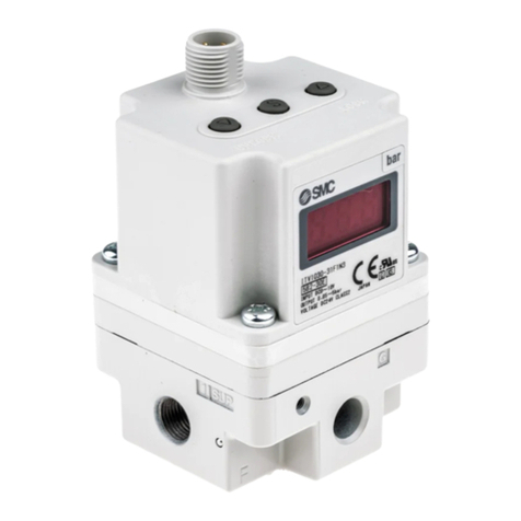
SMC Networks ITV1000 series User manual

SMC Networks IR320-A User manual

SMC Networks

SMC Networks IR320-A User manual

SMC Networks LECP1 Series User manual

SMC Networks

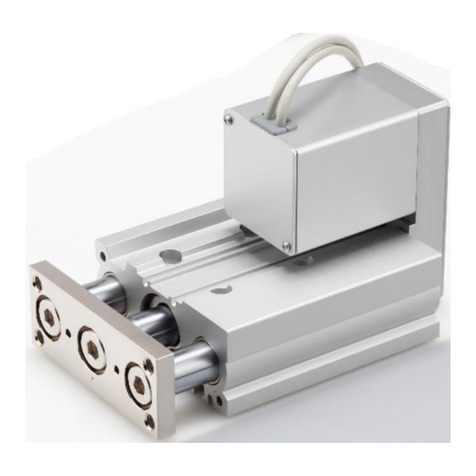
SMC Networks LECP1 Series User manual

SMC Networks JX73 Series Manual

SMC Networks

SMC Networks JX73 Series Manual

SMC Networks IR2000 Series User manual

SMC Networks

SMC Networks IR2000 Series User manual

SMC Networks AS-FS A Series User manual

SMC Networks

SMC Networks AS-FS A Series User manual

SMC Networks RSQx12 series User manual

SMC Networks

SMC Networks RSQx12 series User manual

SMC Networks VXFC-06A User manual

SMC Networks

SMC Networks VXFC-06A User manual

SMC Networks ITV 1 Series User manual

SMC Networks

SMC Networks ITV 1 Series User manual

SMC Networks LES Series User manual

SMC Networks

SMC Networks LES Series User manual

SMC Networks ITV2000-IL Series User manual

SMC Networks

SMC Networks ITV2000-IL Series User manual

SMC Networks PSE303-LBC User manual

SMC Networks

SMC Networks PSE303-LBC User manual

SMC Networks ITV2000 series Manual

SMC Networks

SMC Networks ITV2000 series Manual

SMC Networks JXC73 Series User manual

SMC Networks

SMC Networks JXC73 Series User manual

SMC Networks HEC002-A5 User manual

SMC Networks

SMC Networks HEC002-A5 User manual

SMC Networks JXCL1 Series User manual

SMC Networks

SMC Networks JXCL1 Series User manual

SMC Networks JXC61 User manual

SMC Networks

SMC Networks JXC61 User manual

SMC Networks VBA10A User manual

SMC Networks

SMC Networks VBA10A User manual

SMC Networks Sentry 5000-32-IT User manual

SMC Networks

SMC Networks Sentry 5000-32-IT User manual

SMC Networks RS2H Series User manual

SMC Networks

SMC Networks RS2H Series User manual

SMC Networks LEYG User manual

SMC Networks

SMC Networks LEYG User manual

SMC Networks LECPMJ Series User manual

SMC Networks

SMC Networks LECPMJ Series User manual

Popular Controllers manuals by other brands

Bogen NQ-E7010 Configuration manual

Bogen

Bogen NQ-E7010 Configuration manual

Honeywell S05 Series Product data

Honeywell

Honeywell S05 Series Product data

Elan SC1 installation manual

Elan

Elan SC1 installation manual

KI0BK SBCC Operation manual

KI0BK

KI0BK SBCC Operation manual

Frymaster 3000 instructions

Frymaster

Frymaster 3000 instructions

SENSIRION SFC6000 quick start guide

SENSIRION

SENSIRION SFC6000 quick start guide

Johnson Controls VMA18 Series installation instructions

Johnson Controls

Johnson Controls VMA18 Series installation instructions

TAEHA PROCON-100 Operation manual

TAEHA

TAEHA PROCON-100 Operation manual

Keysight Technologies M9038A Startup guide

Keysight Technologies

Keysight Technologies M9038A Startup guide

Rockwell Automation SMC FLEX quick start

Rockwell Automation

Rockwell Automation SMC FLEX quick start

Regin RCF-230CTD-EC manual

Regin

Regin RCF-230CTD-EC manual

AQTRONIC THC102MX Operation manual

AQTRONIC

AQTRONIC THC102MX Operation manual

ARC RB23STDOPT quick start guide

ARC

ARC RB23STDOPT quick start guide

resideo Aquastat L7224 Series Quick reference guide

resideo

resideo Aquastat L7224 Series Quick reference guide

Assa Abloy InControl 3270 installation guide

Assa Abloy

Assa Abloy InControl 3270 installation guide

Velleman VMB2BL manual

Velleman

Velleman VMB2BL manual

Xantrex Trace C Series Installation and operation guide

Xantrex

Xantrex Trace C Series Installation and operation guide

Contender Shifnoid NC5300 quick start guide

Contender

Contender Shifnoid NC5300 quick start guide

manuals.online logo
manuals.online logoBrands
  • About & Mission
  • Contact us
  • Privacy Policy
  • Terms and Conditions

Copyright 2025 Manuals.Online. All Rights Reserved.