Connections - Digital Section (Left Half)
X10 (MJ1) - RJ11 socket for connection to X10 Interface. DO NOT connect a telephone line
to this socket
TAMP/COM (JP1 ) - Connection to Tamper of Panel and Siren/Bell box. Short the terminal
block with wire if tamper Input is not used. If open this will cause a Tamper Alarm.
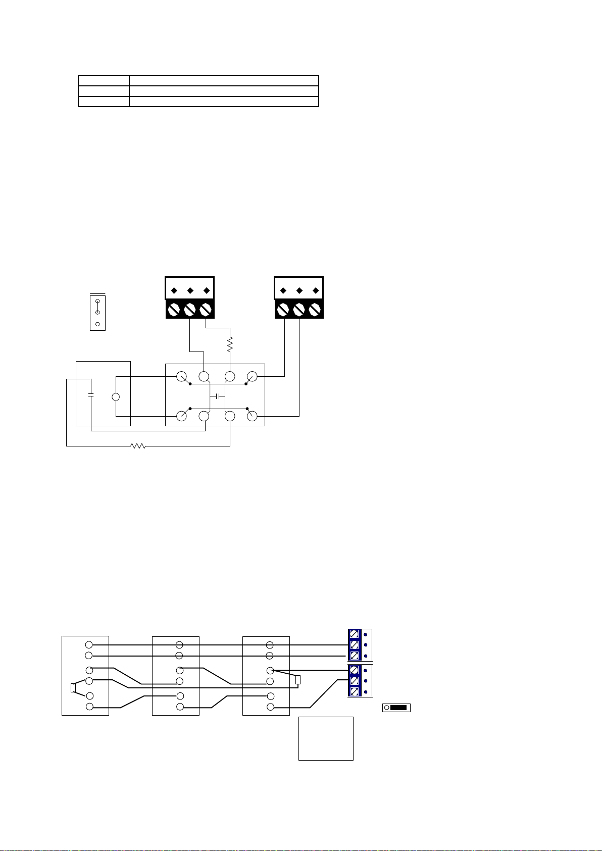
Z1/COM/Z2 (JP3) - Zones 1, 2 Centre Common (3 position terminal block)
Z3/COM/Z4 (JP4 ) - Zones 3, 4 Centre Common (3 position terminal block)
Z5/COM/Z6 (JP5) - Zones 5, 6 Centre Common (3 position terminal block)
Z7/COM/Z8 (JP6) - Zones 7, 8 Centre Common (3 position terminal block)
S12V/COM/12V (JP7) - 12V Unswitched and Switched Supply (3 position terminal block).
Connect Detectors and Smoke/heat sensors supply to 12V/COM. S12V can be programmed
to tun off and on.
KA/KB (JP8) - RS485 connection to keypads, UCMs and other modules (2 position terminal
block). Use WA485 4 way cable and J6 for short distances.
SRN+/SRN- (JP9) - Siren/Bell Connection (12V), SRN- terminal is the negative trigger,
SRN+ is fixed 12V.
STR/12VF/SPK (JP10) - Speaker and Strobe Connection for Speaker and 12V Strobe Light.
Centre pin is at fixed 12V. STR and SPK go to 0V when triggered (negative trigger)
OP1/12V/OP2 (JP11) - Output 1, 2, centre 12V common (3 position terminal block)
OP3/12V/OP4 (JP12) - Output 3, 4, centre 12V common (3 position terminal block)
OP5/12V/OP6 JP13) - Output 5, 6, centre 12V common (3 position terminal block)
OP7/12V/OP8 (JP14) - Output 7, 8 centre 12V common (3 position terminal block)
LEM (J5) - LEM Connector for 10 way ribbon cable.
OP (J12, J13) for OP01 Output driver plug-in module.
RS485 (J6) - 4 way connector for RS485 modules eg UCM, SEM, RIO for short distance only
using 4 way cable (WA485)
Shunts/Settings - Digital Section (Left Half)
ID (J3) - DO NOT SHUNT.
SRNTMP (J4) - Leave this Shunted
JZ1 - JZ8 3x8 way header (EOL Shunts) - Insert shunt in the position nearest the terminals
for the corresponding Zone 1 to 8 if no EOL resistor is used for the zone. Insert a shunt in
the position away from the terminal block if Double EOL resistors: 2K2 connected in series
and 4K7 is connected across the contact.
RESET button (SW1) - Resets Comfort without affecting any programming settings
SPK (VR1) trimmer - adjusts volume of the speaker on SPK/COM output (not BELL)
Shunts/Settings - Analog Section (Right Half)
KPSIR (J56) 2 way header - Volume setting for Siren sounds on Keypads. Shunt for louder
siren volume. This does not affect the BELL volume or the volume of the siren on the SPK
output or the Door station.
J52, J53 - factory settings for echo cancellation tuning. Do not change. Default is J52
Shunted, J53 shunt across pins 2 and 3.
KPMIC (VR51) trimmer - determines microphone signal level from the Keypads. This affects
keypad recording level and Intercom level. Normally set at center. Clockwise to increase
microphone signal level
DPMIC (VR53) trimmer - determines microphone signal level from the Door Stations. This
affects Door Station recording level and Intercom level. Normally set at center. Clockwise to
increase microphone signal level
ECHO (VR52) trimmer - factory adjusted for Echo cancellation. DO NOT adjust
BATT (SW52) - Press to connect backup battery if connected without the AC voltage at
AC14V turned on. If the AC voltage is off and a backup battery is connected, the battery
voltage is not applied to the system until the BATT switch is pressed. Use a non-conducting
tool, eg a pen to press this as it is not easily accessible