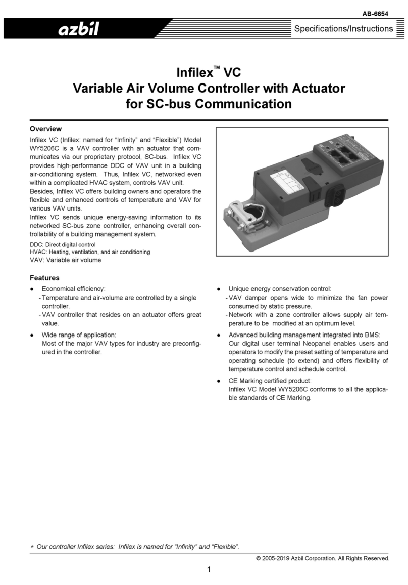
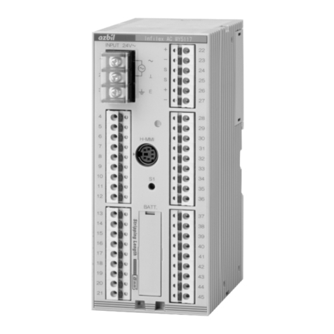
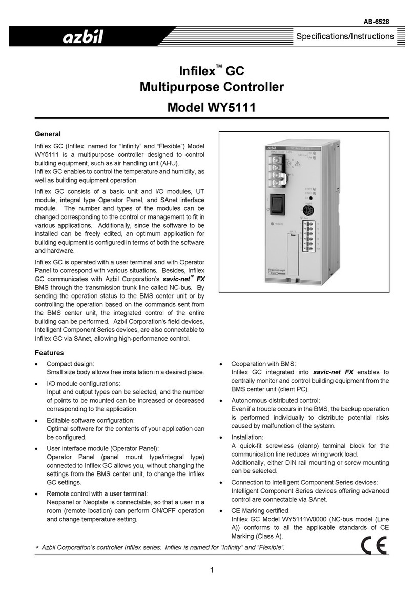
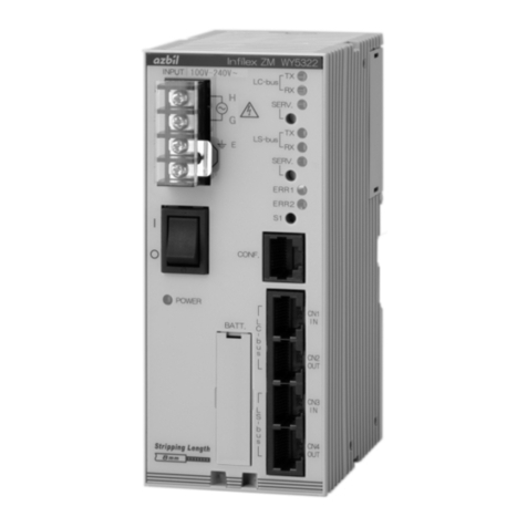
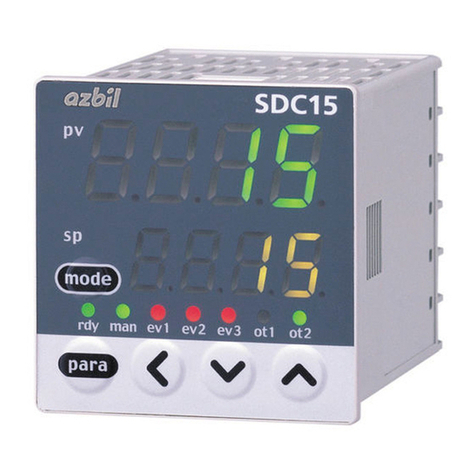
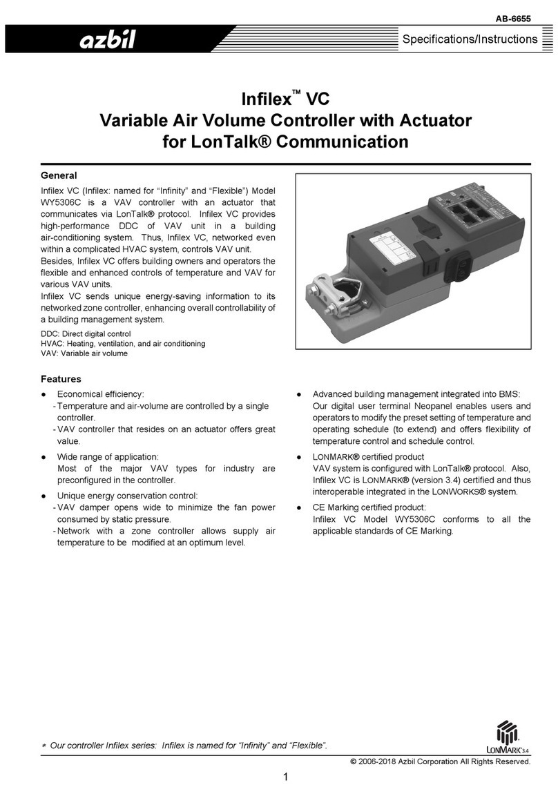
Azbil INFILEX GC WY5311 User manual

AB-6580
∗
Azbil Corporation’s Infilex series controllers: Infilex is named for “Infinity” and “Flexible.”
1
Specifications/Instructions
Infilex™GC
Multipurpose Controller
Model WY5311
General
Infilex GC (Infilex: named for “Infinity” and “Flexible”) Model
WY5311 is a multipurpose controller designed to control
building equipment, such as air handling unit (AHU). Infilex
GC enables to control the temperature and humidity, as well
as building equipment operation.
Infilex GC can be operated with a user terminal and with
Operator Panel. Besides, Infilex GC can communicate with
BMS (building management system) Azbil Corporation’s
savic-net™FX via LonTalk®protocol. By sending the
operation status to the main control unit (monitoring
computer) and by controlling the operation based on the
commands sent from the main control unit, the integrated
control of the entire building can be executed.
Infilex GC consists of a basic unit and connectable I/O
modules (and a user interface module). The number and
types of the modules can be flexibly changed corresponding
to the control or management to fit in various applications.
Additionally, since the software to be installed can be freely
edited, an optimum application for building equipment can be
configured in terms of both the software and hardware.
Features
•Compact design:
Small size body allows free installation in a desired
place.
•Various input/output (I/O) configurations:
Input and output types can be selected, and the number
of points to be mounted can be increased or decreased
corresponding to the application.
•Editable software configurations:
Optimal software for the contents of the application can
be configured.
•User interface module (Operator Panel):
Operator Panel (panel mount type/integral type)
connected to Infilex GC allows you, without changing the
settings from the BMS center unit, to change the Infilex
GC settings.
•Remote control with a user terminal:
Neopanel™or Neoplate is connectable, so that a user at
a remote location can perform ON/OFF operation and
change temperature setting.
•Autonomous distributed control:
Even if a trouble occurs in the BMS, the backup
operation is performed individually to distribute potential
risks caused by malfunction of the system.
•Installation:
A quick-fit screwless (clamp) terminal block is used for
the communication terminal block of the I/O module,
ensuring the labor saving of the wiring work.
Additionally, either DIN rail mounting or screw mounting
can be selected.
•L
ONMARK®certified product:
Infilex GC is LONMARK®certified and thus interoperable
integrated in the LONWORKS®system.
•CE Marking certified product:
Infilex GC conforms to all the applicable standards of CE
Marking (Class A).
AB-6580
2
Safety Instructions
Please read instructions carefully and use the product as specified in this manual. Be sure to keep this manual near by for ready
reference.
Usage Restrictions
This product is targeted for general air conditioning. Do not use this product in a situation where human life may be affected. If
this product is used in a clean room or a place where reliability or control accuracy is particularly required, please contact Azbil
Corporation’s sales representative. Azbil Corporation will not bear any responsibility for the results produced by the operators.
WARNING
•DANGER: To prevent the risk of severe or fatal electrical shock, always disconnect power source and product
power supply before performing any wiring.
•Be sure to ground with 100 Ωor lower ground resistance. Improper grounding may cause electrical shock or
equipment damages.
•Do not detach the terminal cover at any time except when wiring. After wiring, be sure to attach the terminal cover.
Before attaching/detaching the terminal cover, make sure that the wires are not current-carrying to prevent
electrical shock.
•Disconnect power before the product replacement to prevent electrical shock.
•Do not disassemble the product. Disassembly may result in electrical shock or equipment damage.
CAUTION
•Installation and wiring must be performed by qualified personnel in accordance with all applicable safety
standards.
•This product must be operated under the operating conditions (power, temperature, humidity, vibration, shock,
installation position, atmospheric condition, etc) specified in this manual to prevent equipment damages.
•All wiring must comply with local codes of indoor wiring and electric installation rules.
•Use crimp terminal lugs with insulation for electric wires connected to the screw terminals.
•Connect cables to the power source with terminals or the like for permanent connection.
•Make sure all the wires are tightly connected to prevent heat generation or equipment damages.
•If more than the rated power supply voltage is applied, product replacement is required for safety.
•Install this product in a location out of reach of unauthorized people. (e.g. Inside of the control panel cabinet)
•Lightning protection based on regional characteristics and building structure is needed in order to minimize
lightning damages.
•Noise protection is necessary when the product is installed in a location close to many noise sources.
•Do not block the vent holes of the product to prevent equipment damages. Remove protective sheet after
installation and wiring.
•After mounting the product on DIN rail, make sure that the holding parts of all the modules are properly fixed with
their whole parts lifted. The product may drop from the DIN rail and be damaged due to improper mounting.
•Do not plug in or out I/O modules or user interface modules with the product power turned on to prevent equipment
damages.
•Dispose of the lithium battery in accordance with your local regulations.
•Dispose of this product in accordance with your local regulations. Do not reuse all or part of this product.
Trademark information:
Infilex, Neopanel, PARAMATRIX and savic-net are trademarks or registered trademarks of Azbil Corporation in Japan or in other countries.
BACnet is a registered trademark of American Society of Heating, Refrigerating and Air-Conditioning Engineers (ASHRAE).
CompactFlash is a U.S. registered trademark of SanDisk Corporation.
KPEV is a registered trademark of Furukawa Electric Co., Ltd.
LONMARK, LonTalk, and LONWORKS are trademarks of Echelon Corporation registered in the United States and other countries.

AB-6580
3
System Configurations
Infilex GC integrated into BMS: savic-net™FX
Figure 1. System configuration example of BMS-integrated Infilex GC
Notes:
∗MIS may be used instead of SMS and DSS for your system. Note that MIS cannot be mixed with SMS or DSS in the same system.
∗On 1 channel of LC-bus (2 lines for 1 channel), max. 50 remote units (also called ‘controllers’) can be connected. For Infilex ZM, however,
max. 10 units can be connected on LC-bus (5 units per 1 line, 2 lines for 1 channel).
∗Max. wiring length of LC-bus (2 lines for 1 channel) is 900 m.
∗On LS-bus, max. 50 remote units (also called ‘sub-controllers’) can be connected.
∗Max. wiring length of LS-bus is 900 m.
Standalone Infilex GC
LonTalk®
protocol
LS-bus (LonTalk®protocol)
Neopanel™Neoplate
(Digitaluserterminal) (Analog user terminal)
Figure 2. System configuration example of standalone Infilex GC
Notes:
∗On LS-bus, max. 50 controllers can be connected.
∗Max. wiring length of LS-bus is 900 m.
Infilex™AC
Model WY5317C
Infilex™GC
Model WY5311
Infilex™ZM
Model WY5322
Infilex
™
VC
Model WY5306
Infilex
™
FC
Model WY5305
Infilex
™
VC
Model WY5306
Infilex™GC
Model WY5311
Infilex™AC
Model WY5317C
Infilex™GD
Model WY5310
PMX-III*3
Model WY7400
Infilex™ZM
Model WY5322
Infilex
™
FC
Model WY5305
Infilex™VC
Model WY5306
DSS: Data Storage
MIS: Management Integration Server
PMX-III: PARAMATRIX™-III
SCS: System Core Server
SMS: System Management Server
BACnet®IP
(with Web browser)
LC-bus (LonTalk®protocol)
LS-bus (LonTalk®protocol)
Neopanel
™
(Digital user terminal)
Temperature
sensor
Neopanel
™
Model QY7205
(Digital user terminal)
Neoplate Model QY7290
(Analog user terminal)
Infilex
™
SC
Model WY5307
Neopanel
™
(Digital user terminal)
Client PCSMS DSS
MIS
SCS

AB-6580
4
Model Numbers
Model number Description
WY5311 Base model number
W 100 V AC to 240 V AC power
0000 Fixed
Notes:
∗For I/O modules and user interface modules (UT module and integral type Operator Panel) to be combined with Infilex GC Model WY5311,
separate order is required.
∗Regarding I/O modules user interface modules to be combined with Model WY5311, refer to AB-6527 Specifications/Instructions of Model
RY50XX.
Parts for Installation
For details regarding Infilex GC installation, refer to Installation manual of the Infilex series controllers
Part number Description
83165861-001 Screw tab
83104567-001 DIN rail mounting bracket
Note:
For mounting Infilex GC, either the screw tab (for screw mounting) or the DIN rail mounting bracket (for DIN rail mounting) is required. Be
sure to separately order depending on your mounting type.

AB-6580
5
Specifications
Basic specifications
Item Specification
Rated voltage 100 V AC to 240 V AC, 50 Hz/60 Hz
Allowable voltage range 85 V AC to 264 V AC, 50 Hz/60 Hz
Power shutdown
detection 80 V AC or less
Power supply
Power consumption 40 VA
Ambient temperature 0 °C to 50 °C
Ambient humidity 10 %RH to 90 %RH (non-condensing)
Altitude 2000 m or lower
Rated operating
conditions
Vibration Max. 3.2 m/s2at 10 Hz to 150 Hz
Ambient temperature -20 °C to 60 °C
Ambient humidity 5 %RH to 95 %RH (non-condensing)
Vibration for storage Max. 3.2 m/s2at 10 Hz to 150 Hz
Environmental
conditions
Transport/storag
e conditions Vibration for
transportation Max. 9.8 m/s2at 10 Hz to 150 Hz
Green LED ON: Power ON
Power supply (POWER) Green LED OFF: Power OFF
Red LED ON: Major failure or system restart
Major failure (ERR1) Red LED OFF: Normal operation
Red LED ON: Minor failure or system restart
Operation
Minor failure (ERR2) Red LED OFF: Normal operation
LED indication
Communication LC-bus TX: Transmit, RX: Receive, SERV: Service
RAM, RTC* Lithium battery backup
Power failure backup Data file Non-volatile memory (flash memory) backup
Transmission system LonTalk protocol (TP/FT-10 transceiver)
Transmission speed 78 kbps
Transmission distance 900 m (for bus topology connection)
Communications LC-bus
Remote units Max. 50 remote units connectable
Weight 400 g
Material (housing), color Modified PPE, light gray
Power supply, ground M3 (7.62 mm pitch between terminals)
Terminals connection LC-bus communication Modular connector
Note:
∗RTC: Real Time Clock. RTC is backed up by a lithium battery to ensure accurate clocking while the power is OFF.
Wiring specifications
Basic unit
Item Wiring*1Wiring length Condition
Power supply*2JIS*3 IV2.0 mm2or JIS CVV 2.0 mm2or greater ⎯⎯
Ground*2JIS IV 2.0 mm2or JIS CVV 2.0 mm2or greater ⎯Ground resistance: 100 Ωor lower
LC-bus EIA/TIA-568 category 5 or over (φ0.5 ×4 poles) 900 m For bus network topology
Notes
∗1 Pin terminal is not applicable to wiring of Infilex GC.
∗2 M3 screw terminal block is provided for wiring of power supply and ground. Be sure to crimp the crimp terminal lugs on the wire ends.
∗3 JIS: Japanese Industrial Standards

AB-6580
6
I/O module
Item Wiring Wiring length
Temperature input JIS IV, JIS CVV, KPEV®*
1.25 mm2
100 m
Voltage/Current input JIS IV, JIS CVV, KPEV®
1.25 mm2
100 m
Voltage/Current output JIS IV, JIS CVV, KPEV®
0.9 mm2, 1.25mm2
100 m
Modutrol motor output JIS IV, JIS CVV, KPEV®
1.25 mm2
100 m
Digital input JIS IV, JIS CVV, KPEV®
0.5 mm2, 0.75 mm2, 0.9 mm2, 1.25 mm2
100 m
Relay output JIS IV, JIS CVV, KPEV®
1.25 mm2
100 m
Remote control relay
output
JIS IV, JIS CVV, KPEV®
1.25 mm2
100 m
Notes:
∗Since a quick-fit screwless terminal block is provided on I/O modules, the wires can be connected only by stripping the sheath.
Sheath stripped length: 8 mm (Pin terminal cannot be used.)
∗KPEV is a wiring standard provided by Furukawa Electric Co., Ltd.
Specifications of I/O modules, user interface modules, and Operator Panel
For the specifications of I/O modules and user interface modules, refer to Specifications/Instructions of Model RY50XX
(AB-6527). For the specifications of Operator Panel (integral type / panel mount type), refer to Specifications/Instructions of
Model RY5001Q/QY5100W (AB-6546).
CE Marking Conformity
This product must be installed in a panel cabinet. Besides, the product in the panel cabinet must be out of reach of unauthorized
people who are not well-trained for electric facilities.
This product complies with the following Electromagnetic Compatibility (EMC) and the Low Voltage Directive (LVD).
EMC: EN61326-1 Class A, Table 2 (For use in an industrial electromagnetic environment)
LVD : EN61010-1 Overvoltage category II
Pollution degree 2
Input/Output Terminal Arrangement
RJ-45 modular connector
LC-bus
Figure 3. Input/output terminal arrangement
∼
1
2
3
4
CONF.
IN
OUT
100-240 V AC

AB-6580
7
Dimensions
Figure 4. Dimensions (mm)
60 90
140

AB-6580
8
Parts Identification
Figure 5. Parts identification
Table 1. Indication and operation of operating status LED
LED indication LED operation
Data transmitting LC-bus TX LED: flashing
Data receiving LC-bus RX LED: flashing
In SERVICE mode SERV LED: ON (See Table 2 for SERV LED operation.)
Major alarm / initializing ERR1: ON
Minor alarm / initializing ERR2: ON
Table 2. Indication and operation of SERV LED
Status LED indication (□: ON / ■: OFF)
Normal Normal
Applicationless Appli-less
Unconfigured Unconfig
LS-bus error Any indication other than the above.
LED for
operating status
S1 switch*
∗Do not press the S1 switch.
Power switch
LED for
power ON/OFF
Battery holder
Indication tag
DIN rail
mounting
hook
3 sec
1 sec 1 sec

AB-6580
9
Connection of Data Setter for LonTalk Protocol
Connect the CompactFlash®memory type Data Setter (Model QY5111B) for LonTalk protocol to LC-bus port or to CONF. port of
Infilex GC with the Data Setter adaptor (Part No. DY5301S0000, with separate order required.).
For details of the Data Setter adaptor, refer to its Specifications manual.
LC-bus
(LonTalk (For setting Infilex GC and other remote units connected on both
protocol) LC-bus and LS-bus: Connect Data Setter with Data Setter adaptor to
LC-bus port or CONF. port of Infilex GC.)
LS-bus (LonTalk protocol)
Figure 6. Connection example of Data Setter with Data setter adaptor to LC-bus port/CONF. port
Infilex AC
Model WY5317
Infilex GC
Model WY5311
Infilex GD
Model WY5310
Data Setter
adaptor
Model DY5301S
Data Setter
Model QY5111B
Infilex ZM
Model WY5322
Infilex SC
Model WY5307
Infilex FC
Model WY5305
Infilex VC
Model WY5306

AB-6580
10
Maintenance (Lithium Battery Replacement)
Replace the lithium battery for backup (Part No. 83104934-001) for every 5 years.
IMPORTANT:
•Since the remaining battery capacity cannot be checked by measuring the terminal voltage, be sure to replace
the battery every 5 years.
•Only authorized service personnel is allowed to replace the battery.
•Do not touch the power supply unit when replaceing the battery.
•Replace the lithium battery every 5 years if the product is always in use (in ON state).
•Replace the lithium battery with the power ON.
•If the product has never or hardly been operated (in OFF state) for a year, replace the lithium battery before the
product operation.
Battery replacement
∗Replace the lithium battery with Infilex GC in ON state.
Figure 7. Battery replacement
1) Pull out the battery holder using a slotted screwdriver.
2) Disconnect the battery connector and detach the lithium battery from the battery holder.
3) Place a new lithium battery in the battery holder and connect the battery connector to it.
4) Insert the battery holder into the main body.
5) Fill in the date for next replacement (5 years after the replacement) on the indication tag using an oil-based pen.
5)
4)
1)
2)
Lithium battery
for backup
Infilex GC
basic unit
Battery connector
Battery
holder
3)

AB-6580
11
Precautions for Use
•Do not mount the product under the conditions of high temperature and humidity.
•Be sure not to drop the product.
•Be sure to shut down the power (disconnect the wiring between the power supply and the product power terminals) for the
wire replacement.
•Before turning on the power, make sure that wires are correctly connected.
•Do not connect wires to vacant terminals.
•Several tens of seconds are required for the product normal operation after the power is turned on. During this time, the
ERR1 LED (red) for major alarm lights up temporarily, but this does not indicate an error.
•Leave at least 35 mm clearance between the top/bottom surfaces of the product and other devices.
•Peel off the protective sheet on the top surface of the product before turning on the power. (See Fig. 8.)
•For LONMARK®network variables, see “AB-6824 LONMARK®Functional Profile: Open-Loop Actuator.”
Protective sheet
Figure 8. Battery label and protective sheet
Battery label on
the indication tag

AB-6580
Specifications are subject to change without notice.
Building Systems Company
http://www.azbil.com/
Rev. 4.0 Sep. 2015 AB-6580 H (W03)
(J: AI-6580 Rev. 3.1) Printed in Japan.
12
This manual suits for next models
1
Table of contents
Other Azbil Controllers manuals

Azbil
Azbil MY8045A User manual

Azbil
Azbil C15 User manual

Azbil
Azbil Micro Flow MQV9005 User manual

Azbil
Azbil Intelligent Component Series User manual

Azbil
Azbil Micro Flow MQV9020 User manual

Azbil
Azbil SDC15 User manual

Azbil
Azbil KZ03 Series User manual

Azbil
Azbil FRS100 User manual

Azbil
Azbil Infilex AC WY5117C1 Series User manual

Azbil
Azbil AUR450C User manual