manuals.online logo
Brands
  1. Home
  2. •
  3. Brands
  4. •
  5. Gewiss
  6. •
  7. Controllers
  8. •
  9. Gewiss GW96 752 User manual

Gewiss GW96 752 User manual

cod. 7.42.6.873.1
Istruzioni dl montaggio interruttore per protezione motore
Descrizione e funzioni:
L'interruttore per protezione motore è stato sviluppato come interruttore modulare per montaggio su guida DIN, per protezione di motori elettrici
con tensione nominale di lavoro fino a 3x415 V. Esso contiene un dispositivo di sgancio basato su lamine bimetalliche ed uno di tipo magnetico
e permette, tramite una vite di regolazione, I'impostazione della soglia di intervento termico, all'interno del campo di valori regolabili, con un
rapporto di 1:1,6.
Il sistema di chiusura dei contatti è stato derivato dall'interruttore e garantisce un elevato potere di interruzione ed una elevata resistenza al corto
circuito. I contatti sono di tipo a prova di saldatura ed il loro stato viene inequivocabilmente indicato da un segnalatore meccanico di colore
rosso/verde.
Installazione, montaggio e protezione:
L'interruttore è autoprotetto. Ciò significa che in caso di correnti di corto circuito con intensità fino al potere di interruzione nominale non è necessa-
ria alcuna protezione a monte. Per correnti di corto circuito di valore più elevato rispetto al potere di interruzione nominale, bisogna prevedere un
fusibile di protezione secondo tabella.
L'interruttore è adatto al funzionamento con temperatura compresa tra –20 e +50°C.
Funzioni di controllo:
Gli interruttori per protezione motore proteggono il motore in qualsiasi caso, anche in caso di marcia monofase. Nel caso la funzione debba essere
rilevata in campo, è necessario innanzitutto misurare la corrente del motore in condizioni di funzionamento normale e poi regolare il nottolino di
regolazione dell'interruttore al valore corrispondente alla corrente nominale del motore. Poi, tramite marcia monofase o frenatura, si fa aumentare la
corrente assorbita dal motore a 1,5 In. L'interruttore, partendo da caldo, deve intervenire entro due minuti. (L'intervento di un solo fusibile provoca la
marcia monofase e fa intervenire l'interruttore solamente nel caso in cui il motore stia assorbendo la corrente di lavoro. Nel caso il motore sia scari-
co, I'intervento di un solo fusibile non provoca un aumento di corrente tale da far intervenire l'interruttore).
Accessori:
Grazie alla assoluta compatibilità dimensionale di collegamento con gli altri interruttori risulta possibile utilizzare diversi accessori come per esem-
pio bobine di sgancio, contatti ausiliari. Il blocco di segnalazione intervento GW 96 765 permette di distinguere, tramite due contatti in scambio, la
tipologia di intervento (elettrico o manuale) e di generare la relativa segnalazione. Il contatto ausiliario è adatto al comando anche in bassissima
tensione (5V). Risulta possibile inviare un comando od una segnalazione anche a grande distanza, per esempio in stazioni di pompaggio, tramite il
Combinatore telefonico per mezzo della rete telefonica.
Indicazioni:
In linea di principio gli interruttori per protezione motori dovrebbero essere installati in zone con la stessa temperatura dell'ambiente di funziona-
mento del motore. Serrare le viti di fissaggio con coppia di 2-2,5 Nm, controllare il fissaggio dopo il trasporto. Il montaggio, il collegamento e la
messa in servizio dell'interruttore possono essere effettuati solo da personale addestrato ed autorizzato. Nel caso in cui, nonostante il corretto mon-
taggio secondo le istruzioni di servizio, I'interruttore risultasse non funzionante, è possibile che esso sia difettoso e deve essere inviato al costrutto-
re. Ciascun intervento diretto sull'interruttore stesso non è ammesso e scarica il costruttore da qualsiasi responsabilità.
+39 035 946 111
8.30 - 12.30 / 14.00 - 18.00
da lunedì a venerdì
+39 035 946 260
24 ore al giorno
SAT on line
[email protected]
@
SAT
Generalità
Capacità morsetto
Spessore sbarra
Resistenza meccanica
Resistenza agli urti (20 ms)
Temperatura ambiente all’aperto
al chiuso
Peso approssimativo
Grado di protezione
Contatti principali
Tensione nominale d’isolamento (Ui)
Tensione nominale d’impulso (Uimp)
Potere d’interruzione cortocircuito
Corrente termica convenzionale in aria libera lthmax = lemax
Resistenza elettrica a C.A. 3 e le
Potere d’interruzione C.A. 3
Potenza dissipata per ciascun contatto
Interruttore ausiliario
Tensione d’isolamento nominale Ui
Corrente termica nominale lth
Corrente nominale le a CA 13 250 V
440 V
Tipo fusibile (corto circuito) max.
Capacità morsetto (1 o 2 fili)
Sist. di chiusura protetto contro gli spruzzi
Max. potenza dissipata per dispositivi
General
Terminal capacity
Busbar thickness
Mechanical Endurance
Resistance against shock (20 ms)
Ambient temperature open
enclosed
Wight ca.
Degree of protection
Main contacts
Rated insulation voltage Ui
Rated impulse voltage Uimp
Short circuit breaking capacity
Conventional free air thermal current Ithmax = Iemax
Electrical endurense at AC 3 and le
Breaking capacity AC 3
Power loss per contact
Auxiliary switch
Rated insulation voltage Ui
Rated thermal current Ith
Rated current le at AC 13 250 V
440 V
Back-up fuse (short circuit) max.
Terminal capacity ( 1 or 2 wires)
Splash proof enclosure
Max. power loss for contained devices
Généralités
Capacité de la borne
Epaisseur de la barre
Résistance mécanique
Résistance aux chocs (20 ms)
Température ambiante à l’extérieur
à l’abri
Poids approximatif
Degré de protection
Contacts principaux
Tension d’isolation nominale (Ui)
Tension d’impulsion nominale (Uimp)
Pouvoir d’interruption court-circuit
Courant thermique conventionnel à l’air libre lthmax = lemax
Résistance électrique à C.A. e le
Pouvoir de coupure C.A. 3
Puissance dissipée pour chaque contact
Interrupteur auxiliaire
Tension d’isolation nominale Ui
Courant thermique nominal lth
Courant nominal le à CA 13 250 V
440 V
Type de fusible (court-circuit) max.
Capacité de la borne (1 ou 2 fils)
Syst. de fermeture protégé contre les projections d’eau
Puissance dissipée max. pour les dispositifs
Allgemein
Anschliessbare Querschnitte
Querschnitt Verschienung
Mechanische Lebensdauer
Schockfestigkeit (Schockdauer 20 ms)
Umgebungstemperatur offen
gekapselt
Masse ca.
Schutzart
Hauptstrombahnen
Bemessungsisolationsspannung Ui
Bemessungsstossspannungsfestigkeit Uimp
Kurzschlussschaltvermögen
Thermischer Strom Ithmax = Iemax
Elektrische Lebensdauer bei AC 3 und Ie
Motorschaltvermögen AC 3
Verlustleistung pro Schaltstrecke
Hilfsschalter
Bemessungsisolationsspannung Ui
Thermischer Strom Ith
Bemessungsbetriebsstrom Ie bei AC 1 3 250 V
440 V
Vorsicherung zum Kurzschlussschutz max.
Anschliessbare Querschnitte (1 oder 2 Leiter)
Feuchtraumgehäuse 4 TE IP54
Zulässige Verlustleistung der eingebauten Geräte
1 - 25 mm2
0,8 - 2 mm
20.0000 op. cycl.
20 g
-25 … + 50°C
-25 … + 40°C
244/366 g
IP 20
500 V
4 kV
10 kA
40 A
6000 op. cycl.
400 (415) V
2,3W (1,6-10A);
3,3W (16A);
4,5W (25-40A)
440 V
8 A
6 A
2 A
4 A (gL, gG) CLS-HS
0,75 … 2,5 mm2
17W
1 - 25 mm2
0,8 - 2 mm
20.000 StW
20 g
-25… + 50°C
-25… + 40°C
244/366 g
IP 20
500 V
4 kV
10 kA
40 A
6000 StW
400 (415) V
2,3W (1,6-10A);
3,3W (16A);
4,5W (25-40A)
440 V
8 A
6 A
2 A
4 A (gL, gG) CLS-HS
0,75 … 2,5 mm2
17W
1 - 25 mm2
0,8 - 2 mm
20.0000 cicli operativi
20 g
-25 … + 50°C
-25 … + 40°C
244/366 g
IP 20
500 V
4 kV
10 kA
40 A
6000 cicli operativi
400 (415) V
2,3W (1,6-10A);
3,3W (16A);
4,5W (25-40A)
440 V
8 A
6 A
2 A
4 A (gL, gG) CLS-HS
0,75 … 2,5 mm2
17W
1 - 25 mm2
0,8 - 2 mm
20.0000
cycles d’opération
20 g
-25 … + 50°C
-25 … + 40°C
244/366 g
IP 20
500 V
4 kV
10 kA
40 A
6000
cycles d’opération
400 (415) V
2,3W (1,6-10A);
3,3W (16A);
4,5W (25-40A)
440 V
8 A
6 A
2 A
4 A (gL, gG) CLS-HS
0,75 … 2,5 mm2
17W
Dati tecnici Technical data
Donnees techniques Technische daten
GW 96 751 ÷ GW 96 763
GEWISS - MATERIALE ELETTRICO
ULTIMA REVISIONE 10/2007
Instructions for installation manual motor starter
Description and Function:
The manual motor starter is a modular design protective device for DIN busbar installation developed for the protection of electric motors and drives up
to a rated operating voltage of 3 x 415 V. It is equipped with bimetallic and magnetic releases and is thermally adjustable within the indicated rated
current adjustment range by means of an adjustment screw in a ratio of 1:1.6.
The contact system has been derived from miniature circuit breaker and therefore has a high breaking capacity and high short circuit strength. The
contacts are secured against fusing, their switching status is clearly shown by a red/green mechanical indicator.
Installation and Back-Up Fuse Protection:
The protective device has inherent current withstand capability, i.e. no back-up fuse is required for short circuit currents below the breaking capacity. In
case of higher short circuit currents than the rated breaking capacity back-up fuse protection must be provided according to the table. The protective
device is suitable for operation within a temperature range from –20 to +50°C.
Operational Check:
If an operational check is to be made at the place of installation, first measure the motor current during normal operation and set the protective device
adjustment screw according to the rated motor current. Subsequently, increase the current to not less than 1.5 times the rated motor current by braking
or single-phasing. The protective device at operating temperature must trip within 2 minutes. (Switching off a fuse-single phasing-wall lead to the desi-
red result of tripping only when the motor consumes little less than the rated current during normal operation. Otherwise, even during single phasing,
the current consumption will remain below the rated current and the protective device will not trip since in this case the motor is not in danger).
Accessories:
Thanks to the total compatibility of shape and terminals with devices, all accessories, such as releases, auxiliary switches can be used. The tripping
signal switch GW 96 765 is capable of distinguishing between electric tripping and mechanical switchoff by means of one of its two change-over con-
tacts, and gives the respective signal. Message transmission and remote control over large distances, e.g. in case of pump stations, can be achieved
via the telephone network by means of the Telecommander.
Important Notes:
As a rule, manual motor starters and the motors to be protected should be operated at approximately the same room temperature. Fasten terminal
screws with 2 – 2.5 Nm, check terminal connections after transport.
Installation, connection, and starting-up of this protective device is strictly reserved to authorized electrical specialists. If despite taking into account the
instructions for installation, flawless functioning of the device is not achieved, it may be defective and should be forwarded to the manufacturer. Do not
attempt to make any repairs on your own. This would invalidate our warranty.
Montageanleitung Motorschutzschalter
Beschreibung und Funktion
Der Motorschutzschalter ist ein modular aufgebauter Schutzschalter für DlN-Schienenmontage, zum Schutz von Elektromotoren und -antrieben bis
3x415 V Bemessungs - Betriebsspannung. Er besitzt Bimetall- und Magnetauslöser und ist innerhalb des angegebenen Bemessungsstrom-
Einstellbereiches mittels einer Einstellschraube im Verhältnis 1:1,6 thermisch justierbar.
Das Kontaktsystem ist vom Leitungsschutzschalter-abgeleitet und besitzt daher ein hohes Schaltvermögen und eine hohe Kurzschlussfestigkeit. Die
Kontakte sind gegen Verschweissung gesichert, ihr Schaltzustand wird über eine rot/grüne, mechanische Anzeige gut sichtbar und eindeutig gemeldet.
Installation, Montage und Vorsicherung
Der Schutzschalter ist eigenfest, das bedeutet, bis zu Kurzschlussstromstärken unterhalb des Kurzschluss-Schaltvermögens ist keine Vorsicherung
nötig. Bei höheren Kurzschlussstromstärken als dem BemessungsSchaltvermögens ist eine Vorsicherung gemäss Tabelle zu verwenden.
Funktionskontrolle
Soll die Funktion an der Einbaustelle festgestellt werden, so ist zunächst der Motorstrom im Normalbetrieb zu messen und der Einstellknopf des
Schutzschalter dem Motor-Bemessungsstrom entsprechend einzustellen. Danach ist durch Abbremsen oder Einphasenlauf der Strom auf mindestens
den 1,5 fachen Bemessungsstrom des Motors zu steigern. Der betriebswarme Schutzschalter muss innerhalb von 2 Minuten auslösen. (Das
Abschalten einer Sicherung - Einphasenlauf - führt nur dann zum Erfolg "Schalterauslösung", wenn der Motor im Normalbetrieb annähernd den
Bemessungsstrom aufnimmt, sonst bleibt auch bei Einphasenlauf die Stromaufnahme unter dem Bemessungsstrom, da der Motor dann nicht gefähr-
det ist, Iöst der Schutzschalter auch nicht aus).
Zubehör
Durch die absolute Kontur- und Klemmenkompatibilität zu allen Schaltgeräten sind sämtliche Zubehörgeräte wie Auslöser, Hilfsschalter verwendbar.
Der Auslösesignalschalter GW 96 765 kann mit einem der beiden Wechsel-Kontakte zwischen elektrischer Auslösung und mechanischer Abschaltung
unterscheiden und dementsprechende Signalfunktionen erfüllen. Der Hilfsschalter ist Kleinspannungstaublich bis 5V. Eine Fernmeldung und Fern-
steuerung über grössere Distanzen, z.B. bei Pumpstationen, ist mittels Telecommander über das Telefonnetz möglich.
Hinweis
Grundsätzlich sollen Motorschutzschalter und zu schützende Motore bei möglichst ähnlichen Raumtemperaturen betrieben werden. Klemmschrauben
mit 2-2,5 Nm anziehen, nach Transport sichere Klemmung kontrollieren.
Die Montage, der Anschluss und die Inbetriebnahme dieses Schutzschalters darf nur durch eine autorisierte Elektrofachkraft erfolgen. Wird trotz
Beachtung der Montagehinweise keine einwandfreie Funktion des Gerätes erreicht, kann dieses schadhaft sein und ist an den Hersteller einzusenden.
Eigene Eingriffe in den Schalter sind nicht zulässig und schliessen jede Gewährleistung aus!
Instructions pour l'installation disjoncteur moteur
Description et fonction:
Le disjoncteur moteur, conçu d'après est un disjoncteur moteur modulaire pour montage sur rail DIN destiné à la protection de moteurs électriques
monophasés ou triphasés et de systémes de démarrage moteurs jusqu'á une tension nominale de 3 x 41 5 VCA. Il assure une protection thermique et
magnétique. Le réglage de la plage de protection thermique (comprise entre In et 1.6 x In) sópére á l'aide d'une vis de réglage disposée en facade de l'appa-
reil.
La conception de l'appareil au niveau de son systéme de commutation est identique á celle du disjoncteur et dispose de ce fait d'un pouvoir de coupu-
re élevé (10kA) ainsi que d'une trés bonne tenue aux courts-circuits. Les contacts sont protégés contre les soudures et leur position est clairement
signalée par un indicateur mécanique d'état (rouge/vert) bien visible.
Installation, Montage et protection amont:
Le disjoncteur est autonome. Pour des courants de courts-circuits restant compatibles avec le pouvoir de coupure de l'appareil (10kA) et jusqu'á con-
currence de ce dernier, aucune protection amont n'est nécessaire. Pour des courants de courts-circuits supérieur jusqu au pouvoir de coupure, il y a
lieu de prévoir une protection amont par fusible selon tableau ci-dessous. Le disjoncteur est adapté pour une utilisation dans une plage de température
ambiante de –20 à +50°C. De même selon cette norme, la protection est effectuée contre le fonctionnement monophasé (augmentation du courant sur
les deux phases restantes 1.32 x In)
Contrôle du fonctionnement:
Si le réglage de la protection thermique s'opére sur le lieu d'implantation, le courant doit d'abord être mesuré pour un fonctionnement normal. Ensuite
par freinage ou en le faisant marcher sur une phase, augmenter la valeur du courant du moteur au minimum à 1.5 x I nominal. L'échauffement du
disjoncteur doit conduire à son dèclenchement dans les 2 minutes. En cas de rupture de l'un des fusibles (marche monophasée), la protection n'est
effective (déchlenchement du disjoncteur) que si le moteur en fonctionnement normal est alimenté par une valeur de courant proche de la valeur du
courant réglée sur le disjoncteur. Dans le cas contraire même en marche monophasée, I'alimentation du moteur restant inférieur au courant nominal du
disjoncteur, ce dernier ne déchlenchera pas.
Accessoires :
Grâce à sa parfaite compatibilité dimensionnelle de raccordement avec les autres interrupteurs, il est possible d’utiliser divers accessoires comme par
exemple des bobines de décrochage et des contacts auxiliaires. Le verrouillage de la signalisation de déclenchement GW 96 765 permet de distinguer,
à l’aide de deux contacts en commutation, la typologie d’intervention (électrique ou manuelle) et de déclencher le respectif voyant. Le contact auxiliaire
est adapté à la commande même à très basse tension (5V). En utilisant le combiné téléphonique au moyen du réseau, il est possible d’envoyer une
commande ou une signalisation même à grande distance, par exemple dans une station de pompage.
Observations:
En principe, les disjoncteurs moteurs doivent être mis en service á une température ambiante si possible égale à la température ambiante des moteurs
qu'ils protégent.
Couple de serrage des bornes 2 - 2,5 Nm, - Vérification des bornes aprés transport. Le montage, le raccordement et la mise en service doivent être
réalisés par des personnes qualifiées. Si malgré le respect de ces instructions le disjoncteur ne fonctionne pas normalement , prière de le retourner à
votre fournisseur. Une mauvaise manipulation ou une détérioration de l'appareil entraîne l'annulation de la garantie.
Tipo
Type
Type
Type
Campo di regolazione
Adjustment range
Plage de réglage
Einstellbereiche
1-phasing
230-240V 230-240V 400-415V
kW(A) A kW A kW A
3-phasing 3-phasing
GW 96 752
GW 96 753
GW 96 754
GW 96 755
GW 96 756
GW 96 757
GW 96 758
GW 96 759
GW 96 760
GW 96 761
GW 96 762
GW 96 763
0,16 - 0,25
0,25 - 0,40
0,40 - 0,63
0,63 - 1,00
1,00 - 1,60
1,60 - 2,50
2,50 - 4,00
4,00 - 6,30
6,30 - 10,0
10,0 - 16,0
16,0 - 25,0
0,06
0,09
0,12
0,18
0,25
0,37
0,55
0,75
1,1
1,5
2,2
3
0,7
0,7
1,3
1,9
2,4
2,9
4,2
5,6
7,4
8,9
14,5
17,8
0,12
0,9
0,06
0,18
0,25
0,37
0,55
0,8
1,1
1,5
2,5
3
4
5,5
7,5
11,0
0,7
0,5
0,4
1,0
1,4
2,0
2,7
3,2
4,6
6,3
8,7
11,5
14,8
19,6
26,4
38,0
0,25
0,12
0,18
0,09
0,06
0,37
0,55
0,75
1,1
1,5
2,2
2,5 - 3,0
4,0
5,5
7,5
11
15,0
18,5
0,8
0,4
0,6
0,3
0,2
1,1
1,5
1,9
2,6
3,6
5,0
6,6
8,5
11,3
13,2
21,7
29,3
36,0
25,0 - 40,0
This manual suits for next models

11

Other Gewiss Controllers manuals

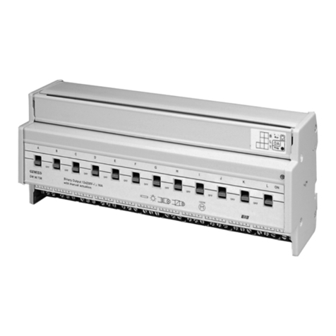
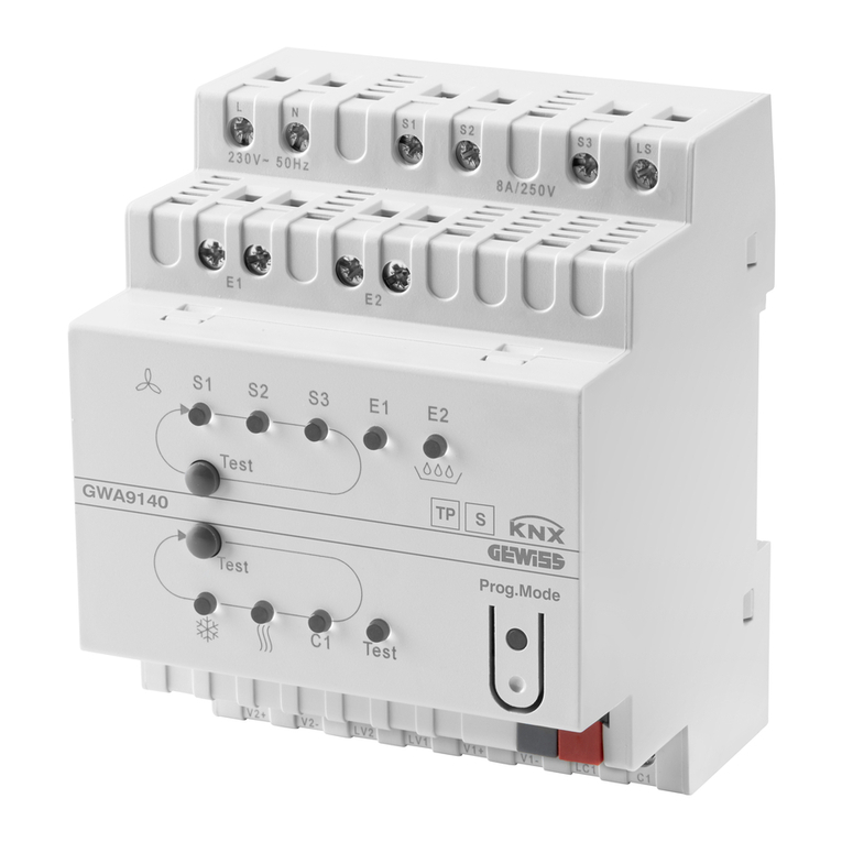
Gewiss CHORUS GWA9140 User manual

Gewiss

Gewiss CHORUS GWA9140 User manual

Gewiss Chorus GW 10 767 User manual

Gewiss

Gewiss Chorus GW 10 767 User manual

Gewiss zigbee CHORUS GWA1531 User manual

Gewiss

Gewiss zigbee CHORUS GWA1531 User manual

Gewiss Chorus GW 10 766 User manual

Gewiss

Gewiss Chorus GW 10 766 User manual

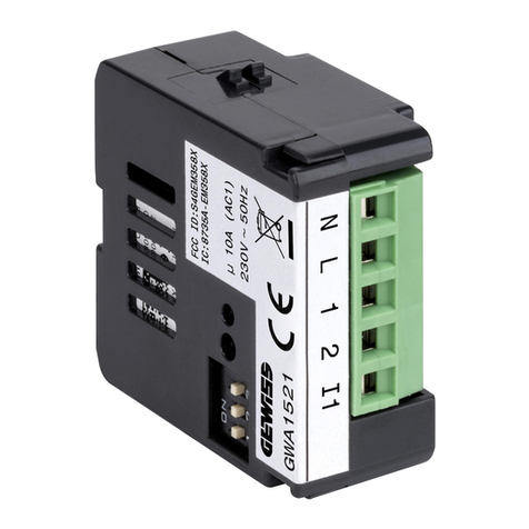
Gewiss Chorus GWA1521 User manual

Gewiss

Gewiss Chorus GWA1521 User manual

Gewiss Chorus GW 90 852 User manual

Gewiss

Gewiss Chorus GW 90 852 User manual

Gewiss Chorus GW 90 835 User manual

Gewiss

Gewiss Chorus GW 90 835 User manual

Gewiss Chorus GW 10 766 User manual

Gewiss

Gewiss Chorus GW 10 766 User manual

Gewiss CHORUS GW 13 766 User manual

Gewiss

Gewiss CHORUS GW 13 766 User manual

Gewiss Chorus GW 90 856 User manual

Gewiss

Gewiss Chorus GW 90 856 User manual

Gewiss Chorus GWA1521 User manual

Gewiss

Gewiss Chorus GWA1521 User manual

Gewiss Chorus GW 10 568 User manual

Gewiss

Gewiss Chorus GW 10 568 User manual

Gewiss Chorus GW 10 801 User manual

Gewiss

Gewiss Chorus GW 10 801 User manual

Gewiss Chorus GW 90 740 User manual

Gewiss

Gewiss Chorus GW 90 740 User manual

Gewiss Chorus GWA1521 User manual

Gewiss

Gewiss Chorus GWA1521 User manual

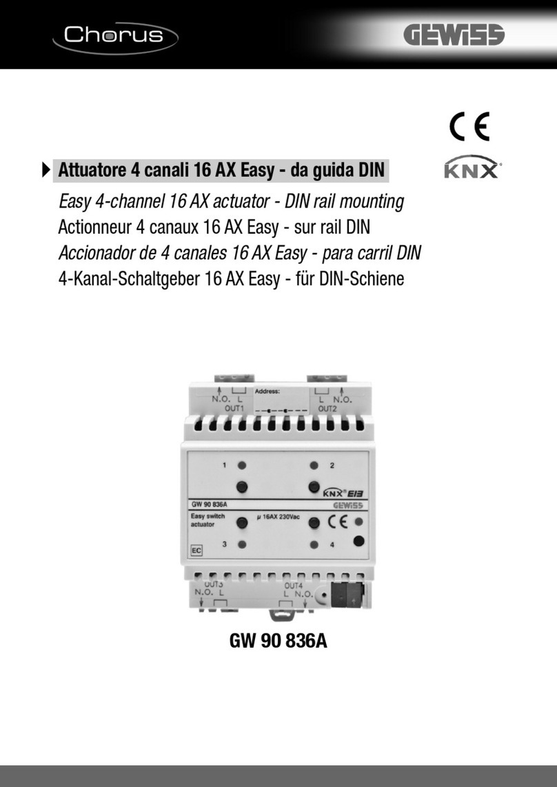
Gewiss Chorus GW 90 836A User manual

Gewiss

Gewiss Chorus GW 90 836A User manual

Gewiss GW 90 738 User manual

Gewiss

Gewiss GW 90 738 User manual

Popular Controllers manuals by other brands

Siemens SIPLUS HCS3200 Compact operating instructions

Siemens

Siemens SIPLUS HCS3200 Compact operating instructions

motortronics Msmart MVC4 Quick setup guide

motortronics

motortronics Msmart MVC4 Quick setup guide

Romotop DIRECT General Installation and Operation Instructions

Romotop

Romotop DIRECT General Installation and Operation Instructions

DayTronic 3700 Series instruction manual

DayTronic

DayTronic 3700 Series instruction manual

NOVAK HAVOC 3S - BASIC SETUP GUIDE V2 4-2010 Setup guide

NOVAK

NOVAK HAVOC 3S - BASIC SETUP GUIDE V2 4-2010 Setup guide

Ricoh RV5VH Applications manual

Ricoh

Ricoh RV5VH Applications manual

American Dynamics VM96 installation instructions

American Dynamics

American Dynamics VM96 installation instructions

Dixon OM Series Operation manual

Dixon

Dixon OM Series Operation manual

Heiland electronic SPLITGRADE user manual

Heiland electronic

Heiland electronic SPLITGRADE user manual

Evikon PluraSens E2408DF user manual

Evikon

Evikon PluraSens E2408DF user manual

dixell XW35VS Installing and operating instructions

dixell

dixell XW35VS Installing and operating instructions

ETC DEBC installation guide

ETC

ETC DEBC installation guide

Tornatech HFX Installation and maintenance manual

Tornatech

Tornatech HFX Installation and maintenance manual

Auber Instruments Auberins KIT-GGP installation guide

Auber Instruments

Auber Instruments Auberins KIT-GGP installation guide

Lennox M0STAT64Q-2 Installation & operation instructions

Lennox

Lennox M0STAT64Q-2 Installation & operation instructions

Crane ACT991M Series installation instructions

Crane

Crane ACT991M Series installation instructions

Hanna Instruments BL 983317-0 instruction manual

Hanna Instruments

Hanna Instruments BL 983317-0 instruction manual

AVE RC10 quick start guide

AVE

AVE RC10 quick start guide

manuals.online logo
manuals.online logoBrands
  • About & Mission
  • Contact us
  • Privacy Policy
  • Terms and Conditions

Copyright 2025 Manuals.Online. All Rights Reserved.