manuals.online logo
Brands
  1. Home
  2. •
  3. Brands
  4. •
  5. United Technologies
  6. •
  7. Security Sensor
  8. •
  9. United Technologies Interlogix RF430I4 Assembly instructions

United Technologies Interlogix RF430I4 Assembly instructions

© 2018 UTC Fire & Security Americas Corporation, Inc. All rights reserved. 1 / 4 P/N 146668999-1 • REV B • ISS 27FEB18
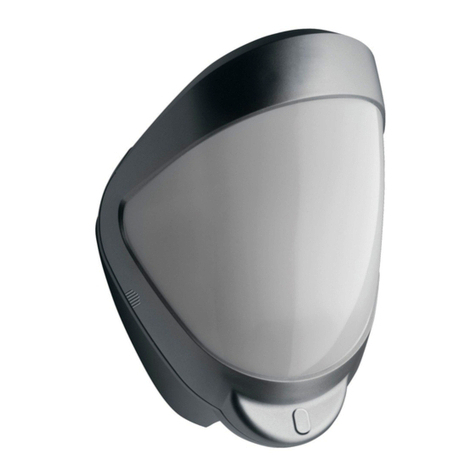
RF430I4 Mini Outdoor Wireless PIR 433 MHz
63 bit Installation Sheet
EN
1
2
3
4
(1)
(2) (2)
(2)
(3)
Top
Bottom
2 / 4 P/N 146668999-1 • REV B • ISS 27FEB18
5
6
7
8
9
10
(1)
(1)
LED
P/N 146668999-1 • REV B • ISS 27FEB18 3 / 4
11
EN: Installation Sheet
Mounting the unit
During installation, protect the electronics against water, as
trapped moisture can affect or damage the unit.
Note: When locating the detector, please ensure the detector’s
field of view is unobstructed.
To mount the detector:
1. Drill the wall to accept the fixing screws using the drilling
template provided. Leave a minimum of 10 cm clearance
above the top of the detector housing to allow the cover
and the detector to be positioned correctly.
2. Remove the back wall fixing plate. Screw the back plate to
the wall. Always ensure that one of the fixing screws is
used to secure the rear tamper plate to the wall (Figure 1,
item 1) as well as using the other screw fixing points
(Figure 1, item 2). Fit the detector main body to the back
plate.
3. Remove the 2 battery compartment screws and remove
the battery compartment cover (Figure 2).
4. Fit the two batteries provided. Please observe the correct
polarity (Figure 3). Replace the battery compartment cover
and secure the 2 fixing screws (Figure 2).
5. Remove the detector cover assembly by loosening the
front locking screw. Use the opening tool as shown in
Figure 4 to carefully lever the front cover away from the
detector base. The cover hinges from the top and lifts out
of the location slot (Figure 5).
6. Fit the detector main body to the back plate.
7. When the detector is aligned and connected, fit the cover
to the detector main body and tighten the locking screw.
Batteries
WARNING: Risk of explosion if the battery is replaced by an
incorrect type.
Only use CR123 3 V lithium batteries (2 x provided). This
ensures 3 years operation under normal conditions.
To extend battery life, a 3rd battery can be fitted into the spare
position within the battery holder (Figure 3).
To preserve battery life the detector has a 2-minute sleep timer
after detection. This is reduced to 5 seconds during walk test.
Multibeam alignment and masking
The detector module is fitted with two sliding shutters to reduce
the detection angle.
The curtains are fitted to the pan and tilt module as shown in
Figure 7. Each section of the detector lens gives a coverage
pattern of approximately 14 degrees.
When coverage exceeds the desired detection area, adjust the
module as required and mask off any beams, either vertically
or horizontally, to avoid unwanted detection.
Use portions of the self-adhesive silver mask applied to the
rear, smooth side of the lens. As an example for pet alley
masking refer to Figure 8. To replace the lens, begin by sliding
one side of the lens into the clips on the pan and tilt module.
After one side is secure, do the same for the opposite side
ensuring the lens is the correct orientation with the smooth side
facing in and the two rows of circles to the bottom.
Always replace the lens the correct way up to ensure exact
beam pattern coverage as shown in Figure 8.
Table 1 below summarizes typical alignment and masking
configurations.
Table 1: Beam alignment & masking configuration
Configuration
Height (m)
Tilt (°)
Max. range (m)
Multibeam,
optimum
3
5
15
Pet immunity [1]
1.5
−2
15
[1] Black area should be masked for pet alley applications up to 15
meters.
Figure 9 shows the pattern for the maximum range in the
optimum position and the top view of the beam pattern.
Selectable options
Figure 6, item 1 shows the Pulse Count selection jumper
positions.
Pulse count
Pulse count is the number of times the detector must detect a
presence before signalling an alarm. Pulse count 1 is the most
sensitive.
4 / 4 P/N 146668999-1 • REV B • ISS 27FEB18
Programming control panels
For outdoor applications it is recommended to use the wireless
detector as a pre-alarm device. Refer to the specific control
panel manuals for details on programming.
Walk test & settling time
Allow 3 minutes for the electronics to settle when power is
applied before commencing the walk test.
The walk test mode starts as soon as either or both tamper
switches are opened. In walk test mode the red LED (figure 10)
is activated. Walk test mode remains active until both tamper
switches are closed i.e. the detector is securely mounted to the
wall and the cover is closed. When both switches have been
closed a 5 minute time will start. After 5 minutes of both
switches being closed, the walk test will finish irrespective of
any detections. Opening either of the tamper switches at any
time will reset the 5 minute count timer.
Whilst in walk test mode the red detection LED will light each
time the wireless detector detects your presence.
Note: When you conduct a walk test, make sure that the front
cover is in place. Do not conduct walk tests with the cover
removed.
The range of the detector increases without the protective front
cover. Therefore the front cover must be fitted to establish the
correct beam pattern. Pan and tilt the lens module over the
field of view to obtain the correct coverage area.
Specifications
Coverage
14° to 70° detection angle,
15 m x 13 m coverage max.
Adjustment
90° pan, 45° tilt
Fresnel lens
20 zones for each detection element, which
can be masked with the curtain sliders
Customised optics
Double silicon shielded quad element
eliminates 50,000 Lux of white light
LED
Red: Walk test indicator
Batteries
2x 3 V CR123 (up to 3 years)*
3x 3 V CR123 (up to 5 years)*
Current
50 μA
Wireless operating
frequency
433 MHz
Maximum power
output
≤10 dBm
Pulse count
1 or 2
Temperature
compensation
Analogue (thermistor) and digital sensitivity
adjustment
Control
Digital microprocessor with non-volatile
memory
Walk test
Output test mode with LED indication.
Operating temperature
−25° to +65°C
Housing
High impact ABS plastic with HDPE cover,
UV stabilised
Dimensions W x H x D
70 mm x 120 mm x 95 mm
Weight
218 g net, 351 g gross
Mounting height
Variable up to 6 m.
Optimum height 3 m for full range
Regulatory information
Manufacturer
UTC Fire & Security Americas Corporation, Inc.
3211 Progress Drive, Lincolnton, NC, 28092,
USA
Authorized EU manufacturing representative:
UTC Fire & Security B.V.
Kelvinstraat 7, 6003 DH Weert, Netherlands
Certification
Environmental
class
IP65
Warnings and
Disclaimers
These products are intended for sale to, and
installation by, an experienced security
professional. UTC Fire & Security cannot provide
any assurance that any person or entity buying its
products, including any “authorized dealer,” is
properly trained or experienced to correctly install
security related products.
For more information on product warnings, refer
to firesecurityproducts.com/policy/product-
warning/ or scan the code.
European Union
directives
UTC Fire & Security hereby declares that this
device is in compliance with the applicable
requirements and provisions of all applicable
rules and regulations, including but not limited to
the Directive 2014/53/EU. For more information
see: https://www.utcfssecurityproducts.eu/
2012/19/EU (WEEE directive): Products marked
with this symbol cannot be disposed of as
unsorted municipal waste in the European Union.
For proper recycling, return this product to your
local supplier upon the purchase of equivalent
new equipment, or dispose of it at designated
collection points. For more information see:
www.utcfssecurityproducts.eu/recycle/.
2006/66/EC (battery directive): This product
contains a battery that cannot be disposed of as
unsorted municipal waste in the European Union.
See the product documentation for specific
battery information. The battery is marked with
this symbol, which may include lettering to
indicate cadmium (Cd), lead (Pb), or mercury
(Hg). For proper recycling, return the battery to
your supplier or to a designated collection point.
For more information see:
www.utcfssecurityproducts.eu/recycle/.
Contact information
www.utcfireandsecurity.com or www.interlogix.com
For customer support, see www.interlogix.com/customer-
support

Other United Technologies Security Sensor manuals

United Technologies Interlogix 5500 Series User manual

United Technologies

United Technologies Interlogix 5500 Series User manual

United Technologies Interlogix TX-E201 Assembly instructions

United Technologies

United Technologies Interlogix TX-E201 Assembly instructions

United Technologies interlogix DDI602 Assembly instructions

United Technologies

United Technologies interlogix DDI602 Assembly instructions

United Technologies Edwards SIGA-OSHD Assembly instructions

United Technologies

United Technologies Edwards SIGA-OSHD Assembly instructions

United Technologies Interlogix TX-E221 Assembly instructions

United Technologies

United Technologies Interlogix TX-E221 Assembly instructions

United Technologies Interlogix TX-E231 Assembly instructions

United Technologies

United Technologies Interlogix TX-E231 Assembly instructions

United Technologies interlogix 5500 Series User manual

United Technologies

United Technologies interlogix 5500 Series User manual

United Technologies Edwards Signature SIGA-OSHD Assembly instructions

United Technologies

United Technologies Edwards Signature SIGA-OSHD Assembly instructions

United Technologies Interlogix RF440I4 Assembly instructions

United Technologies

United Technologies Interlogix RF440I4 Assembly instructions

United Technologies Interlogix DDI602U-F1 Assembly instructions

United Technologies

United Technologies Interlogix DDI602U-F1 Assembly instructions

Popular Security Sensor manuals by other brands

Silux Home Seeker Operation manual

Silux Home

Silux Home Seeker Operation manual

Micropack FDS303 Safety & technical manual

Micropack

Micropack FDS303 Safety & technical manual

Bircher Merkur 2 ES.SM Series Translation of the original instructions

Bircher

Bircher Merkur 2 ES.SM Series Translation of the original instructions

Aritech 2000 Series Installation sheet

Aritech

Aritech 2000 Series Installation sheet

jablotron JA-85B manual

jablotron

jablotron JA-85B manual

SKF TKSU 10 Instructions for use

SKF

SKF TKSU 10 Instructions for use

Nice LP21 User, installation and safety instructions

Nice

Nice LP21 User, installation and safety instructions

Risco ShockTec Plus Grade 3 installation instructions

Risco

Risco ShockTec Plus Grade 3 installation instructions

V-GREAT VG-6647 Installation and operation manual

V-GREAT

V-GREAT VG-6647 Installation and operation manual

Smartwares SH5-TSM-A quick start guide

Smartwares

Smartwares SH5-TSM-A quick start guide

LEGRAND Mosaic 0 489 22 manual

LEGRAND

LEGRAND Mosaic 0 489 22 manual

Extech Instruments DV40 manual

Extech Instruments

Extech Instruments DV40 manual

systemax Poolnanny installation guide

systemax

systemax Poolnanny installation guide

Visonic CLIP SMA Installation

Visonic

Visonic CLIP SMA Installation

GEV LAB 018709 operating instructions

GEV

GEV LAB 018709 operating instructions

Satel COBALT quick start guide

Satel

Satel COBALT quick start guide

PASCO PS-2194 Product guide

PASCO

PASCO PS-2194 Product guide

Bosch ISC-BDL2-W12 installation guide

Bosch

Bosch ISC-BDL2-W12 installation guide

manuals.online logo
manuals.online logoBrands
  • About & Mission
  • Contact us
  • Privacy Policy
  • Terms and Conditions

Copyright 2025 Manuals.Online. All Rights Reserved.