manuals.online logo
Brands
  1. Home
  2. •
  3. Brands
  4. •
  5. United Technologies
  6. •
  7. Security Sensor
  8. •
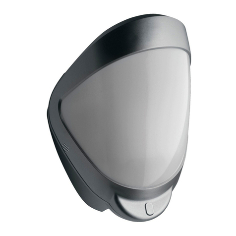
  9. United Technologies Interlogix RF440I4 Assembly instructions

United Technologies Interlogix RF440I4 Assembly instructions

© 2019 UTC Fire & Security Americas Corporation, Inc. 1 / 4 P/N 146669999-1-EN • REV C • ISS 11MAR19
RF440I4 Wireless Outdoor PIR 433 MHz 63 bit
Installation Sheet
EN
1
2
3
4
5
6
7
8
9
10
3m
10 ft.
0 2 4 6 8 10 12 14 16 18 20 22 24 26 28 30 m
0 7 13 20 26 33 39 46 52 59 66 72 79 85 92 98 ft.
0
2 m 7 ft( .)
4 m 13 ft( .)
6 m 20 ft( .)
8 m 26 ft( .)
10 m 33 ft( .)
0°
Long range 30 m 98 ft section( .)
Short / medium range ( .)
to ( .) 6 m 20 ft
20 m 66 ft section
9°
6m
20 ft.
0 2 4 6 8 10 12 14 16 18 20 22 24 26 28 30 m
0 7 13 20 26 33 39 46 52 59 66 72 79 85 92 98 ft.
0
2 m 7 ft( .)
4 m 13 ft( .)
6 m 20 ft( .)
8 m 26 ft( .)
10 m 33 ft( .)
2 / 4 P/N 146669999-1-EN • REV C • ISS 11MAR19
11
12
13
14
15
EN: Installation Sheet
Quick installation
1. Mount the detector following the instructions given later in
this sheet.
2. Fit two CR123 batteries provided into the top battery case.
Observe the polarity. See Figure 4.
The detection LED (green) flashes three times.
3. Wait approximately 2 to 3 minutes to allow the detector to
settle.
4. Press the programming button once to activate walk test
mode.
The detection LED is now enabled for five minutes.
Note: The front cover must be fitted when walk testing.
The default settings are:
•Range: 30 meters / 98 feet
•Pulse count: 1
-°2
MASK THIS SECTION
OFF FOR PET ALLEY
APPLICATIONS UP TO
30 m / 98 ft.
1.5 m
5 ft.
0 2 4 6 8 10 12 14 16 18 20 22 24 26 28 30 m
0 7 13 20 26 33 39 46 52 59 66 72 79 85 92 98 ft.
0
2 m 7 ft( .)
4 m 13 ft( .)
6 m 20 ft( .)
8 m 26 ft( .)
10 m 33 ft( .)
70°
2 m / 7 ft.
6 m / 20 ft.
8 m / 26 ft.
10 m / 33 ft.
12 m / 39 ft.
0
02
74
13 6
20 8
2610
33 12
39 14
46 16
52 18
5920
66 22
72 24
79 26
85 28
92 30
98
2 m / 7 ft.
6 m / 20 ft.
8 m / 26 ft.
10 m / 33 ft.
12 m / 39 ft.
0
m
ft.
02 4 6 8 10 12 14 16 18 20 22 24 26 28 30 m
0713 20 26 33 39 46 52 59 66 72 79 85 92 98 ft. 02 4 6 8 10 12 14 16 18 20 22 24 26 m
0713 20 26 33 39 46 52 59 66 72 79 85 ft.
(1) (2)
P/N 146669999-1-EN • REV C • ISS 11MAR19 3 / 4
Mounting the unit
During installation, protect the electronics against water, as
trapped moisture can affect or damage the unit.
We recommend that the screw mounting holes are sealed from
within the detector using acrylic (non-silicone based) sealants.
Note: When locating the detector, please ensure the detector's
field of view is unobstructed.
To mount the detector:
1. Drill the wall to accept the two fixing screws and the
tamper cup (if used). See Figures 1 and 3.
Notes
•Leave a minimum 10 cm (4 inches) clearance above
the top of the detector housing to allow the cover and
the detector to be positioned correctly.
•We recommend using the tamper cup on uneven wall
surfaces.
•The recommended optimum mounting height for the
detector is 3 m. Whilst it is possible to mount the unit
higher, this will give a reduced detection range and
will require the detection subject to move further
through the already reduced detection area before an
activation is signalled.
2. Remove the cover assembly by loosening the locking
screw. Squeeze the sides of the front cover to release the
internal catches. The cover hinges from the top and lifts
out of the location slot. See Figure 2.
3. Screw the unit to the wall ensuring that the tamper pin is
correctly located and that the tamper microswitch is
closed.
To aid installation, two spare tamper feet are provided.
One is 1 mm shorter and the other is 1 mm longer than the
tamper foot originally fitted. The tamper foot is a push fit
and can be removed by carefully pulling it from the pin.
See Figure 1.
4. When the detector is aligned, connected, and
programmed to suit the installation:
a. Fit the cover to the detector base.
b. Lightly screw the locking screw.
c. Put the top of the locking tool into the small notch on
each side of the cover, and then apply slight pressure
until the cover locks into the base, as shown in
Figure 15.
d. Tighten the locking screw.
Batteries
WARNING: Risk of explosion if the battery is replaced by an
incorrect type.
Only use CR123 3 V Lithium batteries (2X provided). This
ensures 3 years operation under normal conditions.
To extend battery life, a 3rd battery can be fitted into the rear of
the TX board. See Figure 5.
Observe correct polarity when fitting.
To preserve battery life the detector has a 2 minute sleep timer
after a detection. This is reduced to 5 seconds during walk test.
See also “Walk test” on page 4.
Multibeam alignment and masking
The detector module is fitted with two sliding shutters to reduce
the detection angle. Shown in Figure 6. Additional curtain
sliders are provided.
Each section of the detector lens gives a coverage pattern of
approximately 10 degrees.
When coverage exceeds the desired detection area, adjust the
module as required and mask off any beams, either vertically
or horizontally, to avoid unwanted detection.
Use portions of the self-adhesive silver mask applied to the
rear, smooth side of the lens as shown in Figure 11. Gently lift
the top and bottom edges of the pan and tilt module to release
the lens.
Always replace the lens the correct way up to ensure exact
beam pattern coverage. The top of the lens is marked TOP as
shown in Figure 7.
Table 1 below summarizes typical masking configurations for
use when the range option is set to 30 meters.
Table 1: Masking configurations for maximum range
Configuration
Height
(m / ft.)
Tilt (°)
Max. range
(m / ft.)
Reference
Multibeam, optimum
3 / 10
0
30 / 98
Figure 9
Multibeam
6 / 20
9
25 / 82
Figure 10
Pet immunity [1]
1.5 / 5
−2
30 / 98
Figure 11
[1] Black area should be masked for pet alley applications up to
30 meters / 98 feet.
Figure 12 shows the pattern for the maximum range in the
optimum position (see Figure 9). Masking the top section of the
lens reduces the range to 20 m / 66 ft.
LEDs
The device has one green detection LED that is shown in
Figure 14 as item 1.
Programming the detector
Pulse count
Pulse count is the number of times the detector must detect a
presence before signaling an alarm.
When the pulse count is set to 1, the detector is most sensitive.
Figure 14
(1) Programming LED (green)
(2) Programming button
All available settings are listed in Table 2 below.
Table 2: Programming settings
Value
Option
1
2
3
1.
Range (m / ft.)
10 / 33
20 / 66
30* / 98*
2.
Pulse count
1*
2
* Default settings
4 / 4 P/N 146669999-1-EN • REV C • ISS 11MAR19
To change any of settings:
1. Press the programming button to select the option number
you want to change. Press once for range and twice for
pulse count.
2. Wait until the programming (green) LED turns off (typically
4 seconds).
3. Count the number of times the programming LED flashes
to determine the current value for that option.
4. Press the programming button to select the value number
for the new setting. Example: To set the range to 30 m /
98 ft., press three times.
The programming LED blinks twice to indicate that the
new value was set and stored in the NVM.
To reset the detector to the default settings:
1. Remove the batteries from the detector.
2. Press and hold the programming button (Figure 14,
item 2).
3. Put the batteries back. Observe polarity.
4. After the programming LED flashes, release the
programming button.
Programming control panels
For outdoor applications it is recommended to use the wireless
detector as a pre-alarm device. Refer to the specific control
panel manuals for details on programming.
Self-test function
The device has a self-test facility which sends a tamper signal
if a fault is detected. If a fault has been detected, removing the
front cover triggers the detection LED to flash 10 times.
Walk test
To enter the walk test mode, press the programming button
once. The unit can then be aligned. The detection LED lights
every time detection takes place.
The test mode ends automatically five minutes after last
detection. Alternatively, press the program button twice, or
remove and then reapply power to cancel the walk test mode.
Note: When you conduct a walk test, make sure that the front
cover is in place.
Specifications
Detection range
Programmable: 10 m / 30 ft., 20 m /
66 ft., or 30 m / 98 ft.
Coverage
10 to 70° detection angle, 30 x 24 m /
98 x 79 ft. coverage max.
Adjustment
180° pan, 90° tilt
Fresnel lens
28 zones for each detection element,
which can be masked with the curtain
sliders
Customized optics
Double silicon shielded quad element
eliminates 50,000 lux of white light
LED
Green: Detector alarm
Batteries
2X 3 V CR123 (3 years)*
3X 3 V CR123 (up to 5 years)*
Current
50 µA
Wireless operating frequency
433 MHz
Maximum power output
≤10 dBm
Pulse count
1 or 2
Temperature compensation
Analogue (thermistor) and digital
sensitivity adjustment
Control
Digital microprocessor with non-
volatile memory
Walk test
Output test mode with LED indication.
Operating temperature
−25 to +65°C / −13 to 149°F
Housing
High impact ABS plastic with HDPE
cover, UV stabilized
Dimensions, W x H x D
125 x 175 x 130 mm / 4.92 x 6.89 x
5.12 in.
Weight
334 g net, 555 g gross / 11.77 oz net,
19.68 oz gross
Mounting height
Variable up to 6 m / 20 ft.
Optimum height 3 m / 10 ft. for full
range
* Under normal operations
Regulatory information
Manufacturer
Placed on the market by:
UTC Fire & Security Americas Corporation, Inc.
3211 Progress Drive, Lincolnton, NC, 28092, USA
Authorized EU manufacturing representative:
UTC Fire & Security B.V.
Kelvinstraat 7, 6003 DH Weert, Netherlands
Product warnings
and disclaimers
THESE PRODUCTS ARE INTENDED FOR
SALE TO AND INSTALLATION BY QUALIFIED
PROFESSIONALS. UTC FIRE & SECURITY
CANNOT PROVIDE ANY ASSURANCE THAT
ANY PERSON OR ENTITY BUYING ITS
PRODUCTS, INCLUDING ANY “AUTHORIZED
DEALER” OR “AUTHORIZED RESELLER”, IS
PROPERLY TRAINED OR EXPERIENCED TO
CORRECTLY INSTALL FIRE AND SECURITY
RELATED PRODUCTS.
For more information on warranty disclaimers and
product safety information, please check
https://firesecurityproducts.com/policy/product-
warning/ or scan the QR code.
Certification
Environmental
class
IP55
UTC Fire & Security hereby declares that this
device is in compliance with the applicable
requirements and provisions of all applicable rules
and regulations, including but not limited to the
Directive 2014/53/EU. For more information see:
www.utcfssecurityproducts.eu
2012/19/EU (WEEE directive): Products marked
with this symbol cannot be disposed of as
unsorted municipal waste in the European Union.
For proper recycling, return this product to your
local supplier upon the purchase of equivalent
new equipment, or dispose of it at designated
collection points. For more information see:
www.utcfssecurityproducts.eu/recycle/
Contact information
www.utcfireandsecurity.com or www.interlogix.com
For customer support, see www.utcfssecurityproducts.eu

Other United Technologies Security Sensor manuals

United Technologies interlogix DDI602 Assembly instructions

United Technologies

United Technologies interlogix DDI602 Assembly instructions

United Technologies Interlogix TX-E201 Assembly instructions

United Technologies

United Technologies Interlogix TX-E201 Assembly instructions

United Technologies Interlogix 5500 Series User manual

United Technologies

United Technologies Interlogix 5500 Series User manual

United Technologies Edwards Signature SIGA-OSHD Assembly instructions

United Technologies

United Technologies Edwards Signature SIGA-OSHD Assembly instructions

United Technologies Interlogix TX-E221 Assembly instructions

United Technologies

United Technologies Interlogix TX-E221 Assembly instructions

United Technologies Interlogix DDI602U-F1 Assembly instructions

United Technologies

United Technologies Interlogix DDI602U-F1 Assembly instructions

United Technologies Edwards SIGA-OSHD Assembly instructions

United Technologies

United Technologies Edwards SIGA-OSHD Assembly instructions

United Technologies Interlogix RF430I4 Assembly instructions

United Technologies

United Technologies Interlogix RF430I4 Assembly instructions

United Technologies interlogix 5500 Series User manual

United Technologies

United Technologies interlogix 5500 Series User manual

United Technologies Interlogix TX-E231 Assembly instructions

United Technologies

United Technologies Interlogix TX-E231 Assembly instructions

Popular Security Sensor manuals by other brands

urmet domus 1051 quick guide

urmet domus

urmet domus 1051 quick guide

LEGRAND EMOS G1130 manual

LEGRAND

LEGRAND EMOS G1130 manual

hyfire TAURUS TAU-MC-01 quick start guide

hyfire

hyfire TAURUS TAU-MC-01 quick start guide

Siemens FDOOTC441 installation instructions

Siemens

Siemens FDOOTC441 installation instructions

Eterna PIR180BK Safety and installation instructions

Eterna

Eterna PIR180BK Safety and installation instructions

Alecto DBX-10 user manual

Alecto

Alecto DBX-10 user manual

ensto LYNX 4400 Installation and operation manual

ensto

ensto LYNX 4400 Installation and operation manual

Powerfix Profi 278296 Operation and safety notes

Powerfix Profi

Powerfix Profi 278296 Operation and safety notes

Petzl RING L manual

Petzl

Petzl RING L manual

Bosch FCP-500 installation guide

Bosch

Bosch FCP-500 installation guide

BEMKO SES15 Manual instruction

BEMKO

BEMKO SES15 Manual instruction

HST HD201-Mini Installation and maintenance instructions

HST

HST HD201-Mini Installation and maintenance instructions

EMP-Centauri P.117 instruction manual

EMP-Centauri

EMP-Centauri P.117 instruction manual

WatchGas NEO quick start guide

WatchGas

WatchGas NEO quick start guide

Emirel T 01N manual

Emirel

Emirel T 01N manual

Hioki PD3259-90 instruction manual

Hioki

Hioki PD3259-90 instruction manual

Bullard CAB15RAUPGRADE instructions

Bullard

Bullard CAB15RAUPGRADE instructions

Alula RE307 manual

Alula

Alula RE307 manual

manuals.online logo
manuals.online logoBrands
  • About & Mission
  • Contact us
  • Privacy Policy
  • Terms and Conditions

Copyright 2025 Manuals.Online. All Rights Reserved.