Unitronics UMI-S0 Series User manual

Unitronics
1
General Description
This guide provides basic installation information for the UMI-S0xxx series of input and output power
filters intended for use with Unitronics series of inverters.
The UMI-S0xxx series of power filters offer high insertion loss and low leakage current.
Proper filter selection, along with adequate installation and wiring, can help achieving compliance with
IEC/EN 61800-3 emission levels for C2 or C3 environments for Unitronics inverter installations.
You may find additional documentation in the Technical Library in the Unitronics website:
https://unitronicsplc.com/support-technical-library/
Alert Symbols and General Restrictions
When any of the following symbols appear, read the associated information carefully.
Symbol
Meaning
Description
Danger
The identified danger causes physical and property damage.
Warning
The identified danger could cause physical and property damage.
Caution
Caution
Use caution.
Before using this product, the user must read and understand this document.
All examples and diagrams are intended to aid understanding, and do not guarantee operation.
Unitronics accepts no responsibility for actual use of this product based on these examples.
Please dispose of this product according to local and national standards and regulations.
Only qualified service personnel should open this device or carry out repairs.
Failure to comply with appropriate safety guidelines can cause severe injury or property
damage.
Do not attempt to use this device with parameters that exceed permissible levels.
To avoid damaging the system, do not connect/disconnect the device when power is on.
Environmental Considerations
Do not install in areas with: excessive or conductive dust, corrosive or flammable gas,
moisture or rain, excessive heat, regular impact shocks or excessive vibration, in
accordance with the standards given in the product’s technical specification sheet.
Do not place in water or let water leak onto the unit.
Do not allow debris to fall inside the unit during installation.
Ventilation: 10mm space required between controller’s top/bottom edges & enclosure walls.
Electrical Specifications
Filter
Line Voltage
Current [A]
For inverter Side
IEC/EN 61800-3
Environment
UMI-S0020
1Ph 220VAC
10
Input
C2
UMI-S0021
1Ph 220VAC
25
Input
C2
UMI-S0022
3Ph 380VAC
6
Input
C2
UMI-S0023
3Ph 380VAC
16
Input
C2
Inverter power filters
Technical Specifications,
Installation Guide
UMI-S0xxx

Inverter power filters Technical Specifications, Installation Guide
2
Unitronics
Filter
Line Voltage
Current [A]
For inverter Side
IEC/EN 61800-3
Environment
UMI-S0024
3Ph 380VAC
32
Input
C2
UMI-S0025
3Ph 380VAC
45
Input
C2
UMI-S0026
3Ph 380VAC
65
Input
C2
UMI-S0027
3Ph 380VAC
100
Input
C2
UMI-S0028
3Ph 380VAC
150
Input
C2
UMI-S0029
3Ph 380VAC
240
Input
C2
UMI-S0030
1Ph 220VAC
4
Input
C3
UMI-S0031
3Ph 380VAC
7
Input
C3
UMI-S0032
3Ph 380VAC
6
Output
C2
UMI-S0033
3Ph 380VAC
16
Output
C2
UMI-S0036
3Ph 380VAC
32
Output
C2
UMI-S0037
3Ph 380VAC
45
Output
C2
UMI-S0038
3Ph 380VAC
65
Output
C2
UMI-S0039
3Ph 380VAC
100
Output
C2
UMI-S0040
3Ph 380VAC
150
Output
C2
UMI-S0041
3Ph 380VAC
240
Output
C2
UMI-S0250
3Ph 380VAC
400
Input
C2
UMI-S0251
3Ph 380VAC
600
Input
C2
UMI-S0300
3Ph 380VAC
400
Output
C2
UMI-S0301
3Ph 380VAC
600
Output
C2
Filter Selection
The following table lists the suitable filters according to inverter model
and IEC/EN 61800-3 environment:
IEC/EN 61800-3 environment
C3
C2
Inverter Model
Input Filter
Input Filter
Output Filter
UMI-0004BE-B1
UMI-S0030
UMI-S0020
UMI-S0032
UMI-0007BE-B1
UMI-S0030
UMI-S0020
UMI-S0032
UMI-0015BE-B1
UMI-S0030
UMI-S0021
UMI-S0033
UMI-0022BE-B1
UMI-S0030
UMI-S0021
UMI-S0033
UMI-0007EE-B1
UMI-S0022
UMI-S0032
UMI-0015EE-B1
UMI-S0022
UMI-S0032
UMI-0022EE-B1
UMI-S0022
UMI-S0032
UMI-0040EE-B1
UMI-S0023
UMI-S0033
UMI-0055EE-B1
UMI-S0023
UMI-S0033
UMI-0075EE-B1
UMI-S0024
UMI-S0036
UMI-0110EE-B1
UMI-S0024
UMI-S0036
UMI-0150EE-B1
UMI-S0025
UMI-S0037
UMI-0185EE-B1
UMI-S0025
UMI-S0037
UMI-0220EE-B1
UMI-S0026
UMI-S0038
UMI-0300EE-B1
UMI-S0026
UMI-S0038
UMI-0370EE-B1
UMI-S0027
UMI-S0039
UMI-0450EE-B1
UMI-S0027
UMI-S0039

Inverter power filters Technical Specifications, Installation Guide
Unitronics
3
IEC/EN 61800-3 environment
C3
C2
Inverter Model
Input Filter
Input Filter
Output Filter
UMI-0550EE-B1
UMI-S0028
UMI-S0040
UMI-0750EE-B1
UMI-S0028
UMI-S0040
UMI-0900EE-B1
UMI-S0029
UMI-S0041
UMI-1100EE-B1
UMI-S0029
UMI-S0041
UMI-0004CE-B1
UMI-S0031
UMI-S0022
UMI-S0032
UMI-0007CE-B1
UMI-S0031
UMI-S0022
UMI-S0032
UMI-0015CE-B1
UMI-S0031
UMI-S0023
UMI-S0033
UMI-0022CE-B1
UMI-S0031
UMI-S0023
UMI-S0033
UMI-0040CE-B1
UMI-S0024
UMI-S0036
UMI-0055CE-B1
UMI-S0024
UMI-S0036
UMI-0075CE-B1
UMI-S0025
UMI-S0037
UMI-0004BU-B1
UMI-S0030
UMI-S0020
UMI-S0032
UMI-0007BU-B1
UMI-S0030
UMI-S0020
UMI-S0032
UMI-0015BU-B1
UMI-S0030
UMI-S0021
UMI-S0033
UMI-0022BU-B1
UMI-S0030
UMI-S0021
UMI-S0033
UMI-0004CU-B1
UMI-S0031
UMI-S0022
UMI-S0032
UMI-0007CU-B1
UMI-S0031
UMI-S0022
UMI-S0032
UMI-0007EU-B1
UMI-S0031
UMI-S0022
UMI-S0032
UMI-0015EU-B1
UMI-S0031
UMI-S0022
UMI-S0032
UMI-0022EU-B1
UMI-S0031
UMI-S0023
UMI-S0033
UMI-0015EU-B5
UMI-S0022
UMI-S0032
UMI-0022EU-B5
UMI-S0022
UMI-S0032
UMI-0040EU-B5
UMI-S0023
UMI-S0033
UMI-0055EU-B5
UMI-S0023
UMI-S0033
UMI-0075EU-B5
UMI-S0024
UMI-S0036
UMI-0110EU-B5
UMI-S0024
UMI-S0036
UMI-0150EU-B5
UMI-S0025
UMI-S0037
UMI-0185EU-B5
UMI-S0025
UMI-S0037
UMI-0220EU-B5
UMI-S0026
UMI-S0038
UMI-0300EU-B5
UMI-S0026
UMI-S0038
UMI-0370EU-B5
UMI-S0027
UMI-S0039
UMI-0450EU-B5
UMI-S0027
UMI-S0039
UMI-0550EU-B5
UMI-S0028
UMI-S0040
UMI-0750EU-B5
UMI-S0028
UMI-S0040
UMI-0007CU-B5
UMI-S0022
UMI-S0032
UMI-0015CU-B5
UMI-S0023
UMI-S0033
UMI-0022CU-B5
UMI-S0023
UMI-S0033
UMI-0040CU-B5
UMI-S0024
UMI-S0036
UMI-0055CU-B5
UMI-S0024
UMI-S0036
UMI-0075CU-B5
UMI-S0025
UMI-S0037
UMI-0110CU-B5
UMI-S0026
UMI-S0038
UMI-0150CU-B5
UMI-S0026
UMI-S0038
UMI-0185CU-B5
UMI-S0027
UMI-S0039
UMI-0220CU-B5
UMI-S0027
UMI-S0039
UMI-0300CU-B5
UMI-S0028
UMI-S0040
UMI-0370CU-B5
UMI-S0028
UMI-S0040

Inverter power filters Technical Specifications, Installation Guide
4
Unitronics
Environmental
Protection
IP20
Operating temperature
-10°C to 50°C (14°F to 122°F)
Storage temperature
-30°C to 70°C (-22°F to 158°F)
Relative Humidity (RH)
5% to 90% (non-condensing)
Operating Altitude
Below 2,000 m (6,562 ft)
Vibration
≤ 5.8m/s2 (0.6g)
Dimensions
Part Number
L
[mm]
L1
[mm]
L2
[mm]
W
[mm]
W1
[mm]
H
[mm]
Weight
[kg]
Hole
dim.
Ext.
dim.
Wiring
UMI-S0020
180
158
167
70
40
47
1.0
a
A
Screw
terminals
UMI-S0022
201
164
185
80
65
55
1.5
b
UMI-S0032
UMI-S0023
233
196
216
87
65
61
2.5
UMI-S0033
UMI-S0024
222
185
204
105
76
94
3.5
c
UMI-S0036
UMI-S0025
260
213
243
110
90
104
4.0
UMI-S0037
UMI-S0026
310
265
294
125
90
111
4.5
UMI-S0038
UMI-S0027
301
265
240
143
102
106
9.0
d
D
Screw
terminals
UMI-S0039
UMI-S0028
330
290
268
163
104
140
9.0
C
Copper
bars
UMI-S0040
UMI-S0029
483
386
286
220
200
126
11
B
UMI-S0041
UMI-S0250
590
540
508
263
196
210
34
e
C
UMI-S0300
480
430
398
263
196
210
32
UMI-S0251
570
520
488
230
120
145
27
UMI-S0301
480
430
398
230
120
145
22

Inverter power filters Technical Specifications, Installation Guide
Unitronics
5
Note that figures are for illustrative purposes only.
Hole Dimensions
Figure a
Figure b
Figure c
Figure d
Figure e

Inverter power filters Technical Specifications, Installation Guide
6
Unitronics
External Dimensions
Figure A

Inverter power filters Technical Specifications, Installation Guide
Unitronics
7
Figure B

Inverter power filters Technical Specifications, Installation Guide
8
Unitronics
Figure C

Inverter power filters Technical Specifications, Installation Guide
Unitronics
9
Figure D
Installation and Wiring
Do not install in areas with: excessive or conductive dust, corrosive or flammable gas,
moisture or rain, excessive heat, regular impact shocks or excessive vibration, in
accordance with the standards given in the product’s technical specification sheet.
Do not place in water or let water leak onto the unit.
Ventilation: 10mm space required between controller’s top/bottom edges & enclosure walls.
Do not touch live wires.
All wiring activities should be performed while power is OFF.
Use over-current protection, such as a fuse or circuit breaker, to avoid excessive currents
into the unit.
Use wires that are properly sized for the load.
Double-check all wiring before turning on the power to the system.
The filter is recommended to be used in TNC system.
Caution
The input filter cannot be used as an output filter, and vice versa.
The input and output ports of the filter cannot be reversed.
Ensure secure connection of cables to their wiring terminals.

Inverter power filters Technical Specifications, Installation Guide
10
Unitronics
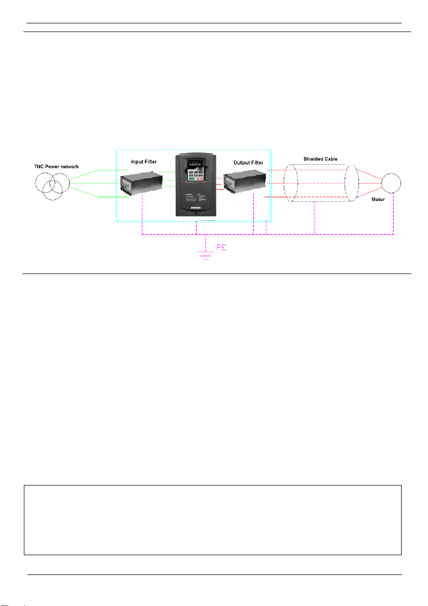
In order to ensure best EMI performance:
Use a metal cabinet. Make sure the cabinet and its doors are properly earthed.
The metal enclosure of the input filter and the enclosure of the inverter need to be tightly-
grounded.
The wiring cable of the filter needs to be short and thick enough.
Input and output cabling of the filter cannot be routed with overlap.
The input and output cable of the filter cannot be routed in parallel with the control cables.
Use shielded twisted-pair cables for inverter control signals.
Use shielded cable for the motor.
The input filter needs to be installed to the inlet of the metal chassis, but the output filter needs to be
installed to the outlet of the metal chassis.
The information in this document reflects products at the date of printing. Unitronics reserves the right, subject to all applicable laws, at any time, at its sole discretion,
and without notice, to discontinue or change the features, designs, materials and other specifications of its products, and to either permanently or temporarily
withdraw any of the forgoing from the market.
All information in this document is provided "as is" without warranty of any kind, either expressed or implied, including but not limited to any implied warranties of
merchantability, fitness for a particular purpose, or non-infringement. Unitronics assumes no responsibility for errors or omissions in the information presented in
this document. In no event shall Unitronics be liable for any special, incidental, indirect or consequential damages of any kind, or any damages whatsoever arising out
of or in connection with the use or performance of this information.
The tradenames, trademarks, logos and service marks presented in this document, including their design, are the property of Unitronics (1989) (R"G) Ltd. or other
third parties and you are not permitted to use them without the prior written consent of Unitronics or such third party as may own them
03/20
This manual suits for next models
24
Table of contents
Other Unitronics Inverter manuals
Popular Inverter manuals by other brands

Northern Lights
Northern Lights L944D, M944W, NL944D2, M30CW, M944T, NL944T2, and... Operator's manual

Lenze
Lenze i550 Series Project planning manual

Omron
Omron 3G3RX2 Series quick start guide

Powtran
Powtran PI8600 Series user manual

Huawei
Huawei SUN2000-50KTL-ZHM3 user manual

Velleman
Velleman PI600BN user manual