manuals.online logo
Brands
  1. Home
  2. •
  3. Brands
  4. •
  5. ADC
  6. •
  7. Measuring Instrument
  8. •
  9. ADC Diagnostix 750 Series User manual

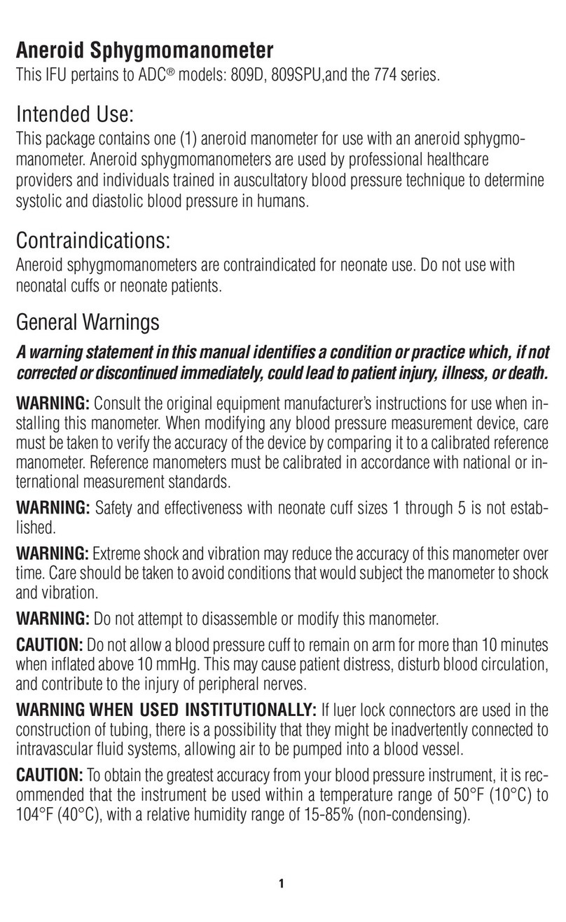
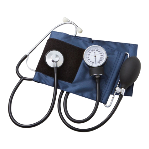
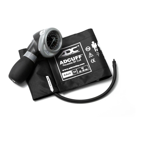
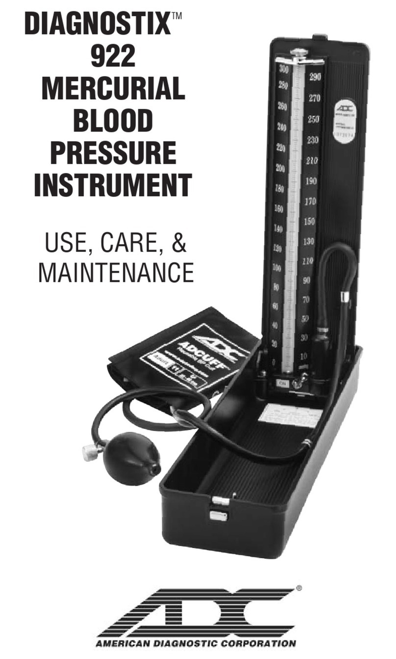
ADC Diagnostix 750 Series User manual

ADC
55 Commerce Drive
Hauppauge, Y 11788
U.S.A.
ADC (UK) Ltd.
Unit 6, PO14 1TH
United Kingdom
Assembled, inspected, and
packaged in the U.S.A.
tel: 631-273-9600
toll free: 1-800-232-2670
fax: 631-273-9659
www.adctoday.com
[email protected]
IB p/n 9350 -00 rev 9 Printed in the U.S.A.
Instructions for Use
Diagnos ixTM Aneroids
Pocke , Palm, Clock Type
®
Inflate the cuff
Close the Adflow valve by turning thumbscrew clockwise.
Palpate the radial artery while inflating the cuff. Be sure to inflate cuff quickly by
squeezing bulb rapidly.
Inflate cuff 20-30 mmHg above the point at which the radial pulse disappears.
NOTE: Cuff pressure range is 0 mmHg to 300 mmHg.
Pos t on the Stethoscope
Position the chestpiece in the antecubital space below the cuff, distal to the brachium.
Do not place chestpiece underneath the cuff, as this impedes accurate measurement.
Use the bell side of a combination stethoscope for clearest detection of the low-
pitched Korotkoff (pulse) sounds.
Deflate the cuff
Open the valve to deflate the cuff gradually at a rate of 2-3 mmHg per second.
Measurement
Record the onset of Korotkoff sounds as the systolic pressure, and the disappearance
of these sounds as diastolic pressure. (Some healthcare professionals recommend
recording diastolic 1 and diastolic 2. Diastolic 1 occurs at phase 4).
NOTE: It is recommended that K4 be used in children aged 3 to 12, and K5 should
be used for pregnant female patients unless sounds are audible with the cuff deflated,
in which case K4 should be used. K5 should be used for all other adult patients.
After measurement is completed, open valve fully to release any remaining air in the
cuff. Remove cuff.
Care and Maintenance
Pocket Gauge: After measurement, fully exhaust cuff then wrap cuff around gauge
and bulb and store in zippered carrying case.
Palm Gauge: After measurement, fully exhaust cuff and store in zippered carrying
case. If unit will not be used for an extended period of time, leave the trigger valve in
the full exhaust position.
Clock Gauge: After measurement, fully exhaust cuff then wrap cuff around bulb and
store in storage compartment.
NOTE: This product will maintain the safety and performance characteristics specified
at temperatures ranging from 50°F to 104°F (10°C to 40°C) at a relative humidity
level of 15% to 85%. This device can safely be stored at temperatures ranging from -
4°F (-20°C) to 131°F (55°C) with a relative humidity of 90%.
Manometer: Your Diagnostix brand pocket aneroid gauge (#800 or #802), palm
aneroid (804N) or clock aneroid (805) requires minimal care and maintenance.
The manometer may be cleaned with a soft cloth but should not be dismantled under
any circumstances.
Should the indicator needle of the manometer rest outside
the oval calibration mark (Figure 5), then the manometer
must be re-calibrated to within ±3 mmHg when compared
to a reference device that has been certified to national or
international measurement standards. A manometer
whose indicator needle is resting outside of this mark, is
NOT acceptable for use.
In the event that the gauge is ever in need of calibration, simply return to ADC.
Damaged or broken parts will be replaced as needed at a minimum charge. Refer to
the warranty for specific details of warranty coverage.
The manufacturer recommends a calibration check every 2 years.
Cuff Cleaning and Disinfecting
Use one or more of the following methods and allow to air dry:
• Wipe with mild detergent and water solution (1:9 solution). Rinse.
• Wipe with Enzol per manufacturer’s instructions. Rinse.
• Wipe with .5% bleach and water solution. Rinse
• Wipe with 70% isopropyl alcohol.
• aunder with mild detergent in warm water, normal wash cycle.
Remove bladder first. Cuff is compatible with 5 wash cycles.
Low-Level Disinfection
Prepare Enzol enzymatic detergent according to the manufacturer’s instructions. Spray
detergent solution liberally onto cuff and use a sterile brush to agitate the detergent
solution over entire cuff surface for five minutes. Rinse continuously with distilled
water for five minutes. To disinfect, first follow the cleaning steps above, then spray
cuff with 10% bleach solution until saturated, agitate with a sterile brush over entire cuff
surface for five minutes. Rinse continuously with distilled water for five minutes. Wipe
off excess water with sterile cloth and allow cuff to air dry.
CAUTION: Do not iron cuff.
CAUTION: Do not heat or steam sterilize cuff.
Manometer Quality Control
A serial number and lot number are
automatically assigned to every aneroid
during manufacturing, ensuring every
item is controlled.
The serial number can be located on the
faceplate of each aneroid (Figure 6).
The lot number is located on the outside
label of the manometer packaging
(Figure 7).
Standards
ANSI/AAMI/ISO 81060-1:2007, EN/ISO 81060-1:2012
Disposal
When your sphygmomanometer or any of its parts have reached their end of life,
please be sure to dispose of them in accordance with all regional and national
environmental regulations. Devices that have become contaminated should be
disposed of in accordance with all local ordinances and regulations.
(Figure 6)
Serial umber
Warranty
ADC®warrants its products against defects in materials and workmanship under
normal use and service as follows:
• Warranty service extends to the original retail purchaser only and commences
with the date of delivery.
• Your Diagnostix™ manometer is warranted for life. The manometer is
warranted to remain accurate to +/-3mmHg (or the prevailing standard) over
its full range when compared to a reference standard for life.
• Inflation system components (cuff, bladder, tubing, bulb, valves, and
connectors) are warranted for three years.
What Is Covered: Replacement of parts, and labor.
What Is Not Covered: Transportation charges to ADC. Damages caused by
abuse, misuse, accident, or negligence. Incidental, special, or consequential
damages. Some states do not allow the exclusion or limitation of incidental,
special, or consequential damages, so this limitation may not apply to you.
To Obta n Warranty Serv ce: Send item(s) postage paid to ADC, Attn: Repair
Dept., 55 Commerce Dr., Hauppauge, NY 11788. Please include your name and
address, phone no., proof of purchase, and a brief note explaining the problem.
Impl ed Warranty: Any implied warranty shall be limited in duration to the terms
of this warranty and in no case beyond the original selling price (except where
prohibited by law). This warranty gives you specific legal rights and you may have
other rights which vary from state to state.
NOTE: Store gauge with
valve in full exhaust position.
(Figure 5)
To register your product visit us at
www.adctoday.com/reg ster
FOR QUESTIO S, COMME TS,
OR SUGGESTIO S CALL TOLL FREE:
1-800-ADC-2670
OR VISIT
www.adc oday.com/feedback
0197
(Figure 7)
9350N-00 rev 9_Layout 1 4/17/19 8:40 AM Page 1
Cuff
Coiled Tubing
Bulb
Valve
Manometer
ADC Aneroid Sphygmomanometer
(manometer, cuff, bladder, bulb and valve)
Thank you for choosing an ADC Diagnostix Aneroid Sphygmomanometer. Your new
aneroid is designed to provide unrivaled durability and unparalleled comfort. Every
component has been carefully designed to maximize performance. This Instructions
for Use guide refers to ADC model series 700, 703, 705, 720, 728, 731, 732, 740,
750, 752, 778, and 788.
Device Description and Intended Use
ADC aneroid sphygmomanometers are used by professional healthcare providers and
individuals trained in the auscultatory blood pressure technique to determine systolic
and diastolic blood pressure in humans.
Contraindications:
Aneroid sphygmomanometers
are contraindicated for neonate use.
Do not use with neonatal cuffs or
neonate patients. Review the size
chart for proper age and limb range
usage (right).
Symbol Definitions
The following symbols are associated with your ADCDiagnostix Aneroid
General Warnings
A warning statement in this manual identifies a condition or practice
which, if not corrected or discontinued immediately, could lead to patient
injury, illness, or death.
WARNING:
Do not allow a blood pressure cuff to remain on patient for more
than 10 minutes when inflated above 10 mmHg. This may cause patient distress,
disturb blood circulation, and contribute to the injury of peripheral nerves.
WARNING:
If luer lock connectors are used in the construction of tubing,
there is a possibility that they might be inadvertently connected to intra-vascular
fluid systems, allowing air to be pumped into a blood vessel. Immediately consult a
physician if this occurs.
WARNING: Safety and effectiveness with neonate cuff sizes 1 through 5 is
not established.
WARNING: If this equipment is modified, appropriate inspection and testing
must be conducted to ensure its continued safe use.
WARNING: Do not apply cuff to delicate or damaged skin. Check cuff site
frequently for irritation.
WARNING: Only use the cuff when the range markings indicated on the cuff
show that the proper cuff size is selected, otherwise erroneous readings
may result.
WARNING: Allow space between patient and cuff. Two fingers should fit in
this space if the cuff is correctly positioned.
WARNING: Do not apply cuff to limbs used for IV infusion.
WARNING: Patient should remain still during measurement to avoid
erroneous readings.
WARNING: When using with an infant or child cuff, extra care must be taken to
prevent over-inflation. With smaller cuffs (infant or child) the cuff can inflate to
over 300mmHg with just two full compressions of the bulb. To prevent discomfort
or injury to the patient and damage to the instrument, bulb should only be partially
squeezed, so that each “stroke” inflates the cuff in 40mmHg to 60mmHg increments
until inflated to the desired level.
CAUTION:
To obtain the greatest accuracy from your blood pressure instrument,
it is recommended that the instrument be used within a temperature range of
50°F (10°C) to 104°F (40°C), with a relative humidity range of 15%-85%
(non-condensing).
CAUTION: Extreme altitudes may affect blood pressure readings. Your device
has been designed for normal environmental conditions.
Operation of Diagnostix Pocket Aneroids
This booklet contains operating and
maintenance information for the
Diagnostix 700, 720, 728, and 778
Series pocket aneroid sphygmo-
manometers. Please read and retain.
Your Diagnostix brand pocket
aneroid sphygmomanometer
consists of an aneroid manometer
(gauge), complete inflation system
(Adcuff calibrated nylon cuff, latex-
free inflation bladder, squeeze bulb,
and Adflow valve), a zippered carry-
ing case, and operating instructions.
Most models are preassembled and ready for use. In units requiring assembly, the
bulb and valve should connect to the tube closest to the Index ine. The gauge con-
nects to the remaining tube.
Operation of Diagnostix
Palm Aneroids
This booklet contains operating and
maintenance information for the
Diagnostix 703 Series, 788 Series,
System 3, Pediatric, General Practice,
System 4, and System 5 Multicuff
instruments. Please read and retain.
Cuff
Index Line
Hang Tab Gauge
Artery Mark
Bulb & Valve
Bladder &
Tubing
Your Diagnostix palm-style aneroid manometer with integral bulb and trigger air release
valve (#804N), Adcuff calibrated cuff with Size Guide™marking system, bladder, bayonet-
style connector (attached to bladder tubing), zippered carrying case, and instruction book-
let. ADC’s Multicuff Systems (System 3, 4, 5, GPK, and PMK) contain the #804N manome-
ter and a variety of cuffs with single tube bladders, each equipped with a bayonet-style
connector, and a compartmentalized case.
Connecting Palm Style Model: 804
Legacy Connector: Assemble the supplied luer slip
connector into the connector port on top of palm gauge,
rubber gasket side down. Make sure connector is fully
seated in the connector port. Slide cuff tubing over the
barbed end of the connector. Connector will friction fit onto
the tubing of most commercially available ONE-tube cuff
and bladder systems (Figure 1).
New 804N Connector: Insert white bayonet connector
into metal receiver until it clicks (Figure 2).
To Release: Slide receiver collar downward toward gauge
until connector releases.
WARNING: Do NOT remove metal receiver from gauge.
WARNING: The palm style manometer is designed
for use with ONE-tube systems.
WARNING: To avoid damage to the instrument, do not force
connector into port.
Using the Trigger Valve
Deflat on: Gently squeeze the bottom of the trigger to deflate the cuff.
Altering the pressure affects the deflation rate.
Rap d Exhaust: To exhaust remaining air after measurement is
completed, squeeze trigger until it clicks and locks in place.
Caution: Never force trigger.
Operation of Diagnostix Clock Aneroids
This booklet contains operating and maintenance information
for the Diagnostix 750W series (wall mount), 752M series
(mobile), and 750D series (desktop) aneroid
sphygmomanometers. Please read and retain.
Your Diagnostix 750/752 consists of a large
“clockface” aneroid with easy-to-read 6” dial, an
integral swivel bracket/cuff storage compartment
(wall series only), complete inflation system
(which includes the Adcuff nylon cuff with Size
Guide marking system, latex-free inflation
bladder, bulb, and Adflow valve), 8-foot length coiled tubing,
luer connectors, mounting hardware, and operating instructions. The Diagnostix 752M is
mounted on a height adjustable, Spider- eg™5-leg mobile stand. The Diagnostix 750D is
mounted on a desktop stand.
To assemble the inflation system, connect coiled tubing to air inlet nipple at bottom of gauge.
Insert male luer adapter on bladder tubing into female receptacle at free end of coiled tubing.
Store folded inflation system in swivel bracket behind gauge on 750W and 750D or in integral
basket on 752M.
Adcuff Intended Use:
ADC blood pressure cuffs are noninvasive and are intended for use with manual and
automated noninvasive blood pressure measurement devices.
ADC’s Size Guide marking system assures use of correct cuff size and proper cuff
alignment. Printed Index and Range markings and applicable limb range (in cm)
allow easy identification of the correct cuff size. An artery mark printed on both sides
indicates bladder midpoint for correct cuff positioning. A convenient nylon gauge
hang tab permits flexible use with either pocket aneroids or mercury manometers.
Hook-and-loop adhesive surface provides a snug, infinitely variable fit and is
designed to withstand a minimum of 30,000 open/close cycles.
Measurement Procedure
Pat ent Pos t on
The patient should sit or lie comfortably. The arm should be fully supported on a
flat surface at heart level. (If the arm’s position varies, or is not level with the heart,
measurement values obtained will not be consistent with the patient’s true blood
pressure.) When seated, the patient should have their back and arm supported, and
their legs should not be crossed. Prior to measurement the patient should relax
comfortably for five minutes and should refrain from talking or moving during
measurement. Observer should view manometer in a direct line to avoid “parallax error.”
Apply the cuff
Adcuff nylon cuffs are specially designed
to promote the precisely accurate determi-
nation of blood pressure. Index and range
markings ensure use of the
correct cuff size. The artery mark
indicates proper cuff positioning.
Place the cuff over the bare upper arm with the artery mark positioned directly over
the brachial artery. The bottom edge of the cuff should be positioned approximately
one inch (2-3cm) above the antecubital fold. Wrap the end of the cuff not containing
the bladder around the arm snugly and smoothly and engage adhesive strips (Figure 3).
To verify a correct fit, check that the Index ine falls between the two Range ines
(Figure 4).
Left Arm
Tube
(Figure 3)
Cuff S ze Lmb Range
Inches CM
Infant 7I 3.5 to 5.5 9 to 14
Ch ld 9C 5.1 to 7.6 13 to 19.5
Sm. Adult 10SA 7.4 to 10.6 19 to 27
Adult 11A 9 to 15.7 23 to 40
Lg. Adult 12X 13.3 to 19.6 34 to 50
Th gh 13T 15.7 to 25.9 40 to 66
Bar atr c 12BX 17.3 to 25.9 44 to 66
Size Chart
Index Line
TM
13
T
12
X
10
SA
9
C
7
I
11
A
Adult - 11
23-40 cm
11
TM
23-40 cm
Reusable BP Cuff
1
1
Gauge Hang Tab
Bladder FlapArtery Mark
Size Icons
Hook & Loop
Closure Adhesive
Range Lines
Index Line Artery Mark
Index Line
Index Line
Range Lines
Index Line Artery Mark
Select Smaller Cuff
Correct Cuff S ze
Select Larger Cuff
(Figure 4)
Cuff
Bladder Tubing
Trigger Valve
Gauge
Artery Mark
Connector Port

(Figure 1)
(Figure 2)
Symbol Defnt on
Important warning/caution
Phthalate free
Circumference size
LATEX
Symbol Defnt on
Conforms to EU standards
Authorized European
represenative’s information
Manufacturer’s information
Temperature limit
Humidity limitation
°F
Not made with natural
rubber latex
9350N-00 rev 9_Layout 1 4/17/19 8:40 AM Page 2

This manual suits for next models

6

Other ADC Measuring Instrument manuals

ADC Prosphyg 760 User manual

ADC

ADC Prosphyg 760 User manual

ADC Diagnostix Palm Style Aneroid Maintenance manual

ADC

ADC Diagnostix Palm Style Aneroid Maintenance manual

ADC GNOSTIX 922 Maintenance manual

ADC

ADC GNOSTIX 922 Maintenance manual

ADC DIAGNOSTIX 932 series Maintenance manual

ADC

ADC DIAGNOSTIX 932 series Maintenance manual

ADC DIAGNOSTIX 922 series Maintenance manual

ADC

ADC DIAGNOSTIX 922 series Maintenance manual

ADC MGA3000 series User manual

ADC

ADC MGA3000 series User manual

ADC advantage connect 6024N User manual

ADC

ADC advantage connect 6024N User manual

ADC 774 Series User manual

ADC

ADC 774 Series User manual

ADC advantage connect 6024N User manual

ADC

ADC advantage connect 6024N User manual

Popular Measuring Instrument manuals by other brands

Siemens SITRANS F FCS400 quick start

Siemens

Siemens SITRANS F FCS400 quick start

Elko iNELS Air AirSS-100L manual

Elko

Elko iNELS Air AirSS-100L manual

AMTAST AMT-316 Operation manual

AMTAST

AMTAST AMT-316 Operation manual

Sibelmed DATOSPIR MICRO B Quick reference guide

Sibelmed

Sibelmed DATOSPIR MICRO B Quick reference guide

Enovation Controls Murphy CONNECT installation manual

Enovation Controls

Enovation Controls Murphy CONNECT installation manual

Garmin LIDAR-LITE V3HP OPERATION MANUAL AND TECHNICAL SPECIFICATIONS

Garmin

Garmin LIDAR-LITE V3HP OPERATION MANUAL AND TECHNICAL SPECIFICATIONS

Hioki CM3286-01 quick start guide

Hioki

Hioki CM3286-01 quick start guide

FLIR CM55 user manual

FLIR

FLIR CM55 user manual

Cleveland Controls A-08740 0 Series instruction manual

Cleveland Controls

Cleveland Controls A-08740 0 Series instruction manual

NLS X-32 instructions

NLS

NLS X-32 instructions

Atlas Copco ACTA 3000 Guide to using

Atlas Copco

Atlas Copco ACTA 3000 Guide to using

ROOTECH ACUURA 2350-TEMP user guide

ROOTECH

ROOTECH ACUURA 2350-TEMP user guide

Endress+Hauser Levelflex FMP53 technical information

Endress+Hauser

Endress+Hauser Levelflex FMP53 technical information

PCB Piezotronics IMI SENSORS 601A62 Installation and operating manual

PCB Piezotronics

PCB Piezotronics IMI SENSORS 601A62 Installation and operating manual

Koso XR-01S instructions

Koso

Koso XR-01S instructions

Leica Geosystems Roteo 20HV user manual

Leica Geosystems

Leica Geosystems Roteo 20HV user manual

Kestrel Sportsman 4500 instruction manual

Kestrel

Kestrel Sportsman 4500 instruction manual

GE AquaTrans AT600 user manual

GE

GE AquaTrans AT600 user manual

manuals.online logo
manuals.online logoBrands
  • About & Mission
  • Contact us
  • Privacy Policy
  • Terms and Conditions

Copyright 2025 Manuals.Online. All Rights Reserved.