manuals.online logo
Brands
  1. Home
  2. •
  3. Brands
  4. •
  5. Dakota Digital
  6. •
  7. Measuring Instrument
  8. •
  9. Dakota Digital MCL-4073S/R User manual

Dakota Digital MCL-4073S/R User manual

MAN# 650186B
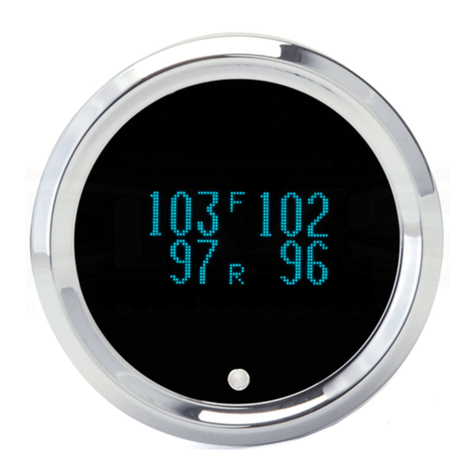
MCL-4000 SERIES 1-7/8” LED OIL TEMPERATURE GAUGE rev. A
MCL-4073S/R
•Selectable ranges (0°F to 310°F) or (-17°C to 154 °C) with SEN-1041
(32°F to 404°F) or (0°C to 205°C) with SEN-1043
(22°F to 301°F) or (-5°C to 149°C) with SEN-1044
•User adjustable high temperature warning point
•Optional display dimming feature
MOUNTING
The MCL-4000 series gauge requires a round hole 1-7/8” diameter. It should be inserted into the opening from
the front and the U-clamp will be installed from the back. Tighten the two nuts on the U-clamp so that the gauge is secure.
Gauge depth to the back of the case is approximately 1-3/8”. Gauge depth including the mounting studs is about 2-1/8”.
TEMPERATURE GAUGE SETUP
The green wire in the harness is used to enter setup and change/select settings. This is done by
powering the green wire with +12V or releasing it. To power the green wire, touch the wire to a +12V source.
To release the wire, remove the green wire from the source. The gauge moves through the setup in the
following order:
Software code > Sender selection > High temperature warning > done
default settings: 30F (SEN-1041) 202°F high wa rning point
1. Make sure the key is off so the gauge is not powered.
2. Power the green wire while turning the key on.
3. The display will show “Lt1“, this is the software code. (Newer software versions may have a different code.)
4. Release the green wire. The display will read “Snd” (temperature sender selection).
5. Power and release the green wire. The currently selected temperature sender type is displayed. The
options are as follows:
“30F” °F SEN-1041 “15C” °C SEN-1041
“40F” °F SEN-1043 “20C” °C SEN-1043
“29F” °F SEN-1044 “14C” °C SEN-1044
6. Power and release the green wire until your temperature sender is displayed.
7. Power and hold power to the green wire to store the sender setting.
MAN# 650186B
8. “HI” (high temperature warning) will be displayed. Release green wire.
9. Power and release the green wire to adjust the high temperature warning point.
10. Power and hold power to the green wire to store the high temperature warning point.
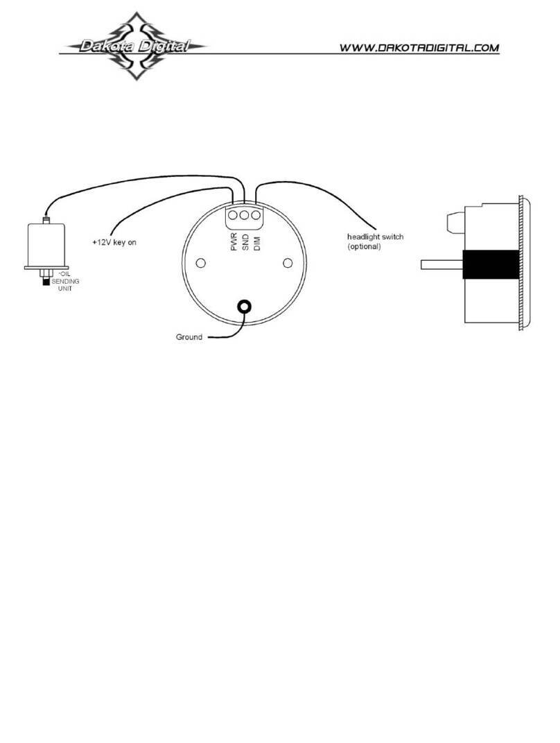
POWER RED WIRE
Connect the red wire from the main harness to accessory power from the ignition switch.
Never connect this to a battery charger alone. It needs to have a 12 volt battery connected to it. Battery chargers
have an unregulated voltage output that will cause the system to not operate properly.
GROUND BLACK WIRE AND RING TERMINAL
The black wire is the main ground for the gauge. A poor ground connection can cause improper or erratic
operation. Connect the ring terminal to one of the mounting studs after the clamp has been installed before the thumb nut
is screwed on to secure the gauge.
TEMPERATURE SENSOR GREY WIRE
The gray wire connects to the temperature sensor. DO NOT use Teflon tape on the sender threads as the sender
grounds through the threads to a body ground. Using Teflon tape will prevent body grounding and will cause an error in the
temperature reading. If the sender mounting prevents body grounding (i.e. mounting into plastic fittings) a grounding wire
will need to be clamped to the body of the sender and connected to a good ground.
FUNCTION WIRE GREEN WIRE
The function wire (green wire) is used to change settings on the gauge as described above in the setup section.
This is done by touching and removing the wire to +12V.
NIGHT DIMMING BLUE WIRE
Your display system has a dimming feature that reduces the display intensity. Normally the system is at full
brightness for daytime viewing. When the blue wire has 12 volts the display intensity will be reduced. The blue wire can be
connected to +12v through a switch to allow the dimming feature to be turned on or off. To have the system at full
brightness all of the time, leave the blue wire disconnected.
TROUBLESHOOTING GUIDE
Problem Possible cause Solution
Gauge will not light up. Red wire does not have power.
Black wire is not getting a good ground.
Gauge is damaged.
Connect to a location that has power.
Connect ground to a different location.
Return gauge for repair.
Gauge displays or flashes
“EEE”.
Gray wire is not connected properly.
Sender has poor / no ground.
Temperature is lower than range of
sensor.
Check connection from gray wire to sender.
Check for good sender ground, remove any sealant
tape for the threads of sender.
This occurs at temperatures below freezing. Once in
range, correct temperature will be displayed.
Gauge displays or flashes
“---“. Grey wire is shorted to ground.
Temperature is above range of sender.
Check grey wire for breaks in insulation or pinched
areas.
Take action to prevent further heating. If common
problem, use higher temperature sender.
Gauge always flashes. High warning point set too low. Adjust the high warning point using the setup menu.
Gauge will not dim. Blue wire is not connected correctly. Check wiring. Blue wire should have 12 volts when
dimming is desired.
Gauge remains dim at all times. Blue wire is getting power all of the time. Connect blue wire to +12v through a switch or leave
unconnected.
Gauge will not go into the
SETUP mode. Green wire is not powered at key on.
Make sure to touch the green wire to a +12V source
when turning on key.
Check to make sure the point where the green wire
is touched does have +12V using a voltmeter.
Gauge displays “Er” followed by
a number or letter. Some of the setup data has been lost or
corrupted. Reset all settings in the SETUP menu to ensure they
are correct.
Gauge does not read correctly. Incorrect sender type selected. Select correct sender type using SETUP menu.
MAN# 650186B
SERVICE AND REPAIR
DAKOTA DIGITAL offers complete service and repair of its product line. In addition, technical consultation is available to help you work through any questions or
problems you may be having installing one of our products. Please read through the Troubleshooting Guide. There, you will find the solution to most problems.
Should you ever need to send the unit back for repairs, please call our technical support line, (605) 332-6513, to request a Return Merchandise Authorization
number. Package the product in a good quality box along with plenty of packing material. Ship the product by UPS or insured Parcel Post. Be sure to include the RMA number
on the package, and include a complete description of the problem with RMA number, your full name and address (street address preferred), and a telephone number where you
can be reached during the day. Any returns for warranty work must include a copy of the dated sales receipt from your place of purchase. Send no money. We will bill you after
repair.
Dakota Digital 24 Month Warranty
DAKOTA DIGITAL warrants to the ORIGINAL PURCHASER of this product that should it, under normal use and condition, be proven defective in material or
workmanship within 24 MONTHS FROM THE DATE OF PURCHASE, such defect(s) will be repaired or replaced at Dakota Digital’s option.
This warranty does not cover nor extend to damage to the vehicle’s systems, and does not cover removal or reinstallation of the product. This Warranty does not
apply to any product or part thereof which in the opinion of the Company has been damaged through alteration, improper installation, mishandling, misuse, neglect, or accident.
This Warranty is in lieu of all other expressed warranties or liabilities. Any implied warranties, including any implied warranty of merchantability, shall be limited to
the duration of this written warranty. Any action for breach of any warranty hereunder, including any implied warranty of merchantability, must be brought within a period of 24
months from date of original purchase. No person or representative is authorized to assume, for Dakota Digital, any liability other than expressed herein in connection with the
sale of this product.

This manual suits for next models

1

Other Dakota Digital Measuring Instrument manuals

Dakota Digital Series II User manual

Dakota Digital

Dakota Digital Series II User manual

Dakota Digital VHX-67C-CAM-K-B User manual

Dakota Digital

Dakota Digital VHX-67C-CAM-K-B User manual

Dakota Digital MLX-9X00 Series User manual

Dakota Digital

Dakota Digital MLX-9X00 Series User manual

Dakota Digital BIM-22-3 User manual

Dakota Digital

Dakota Digital BIM-22-3 User manual

Dakota Digital HLY-3027 User manual

Dakota Digital

Dakota Digital HLY-3027 User manual

Dakota Digital VHX-84B-REG VHX-84B-REG-S-W User manual

Dakota Digital

Dakota Digital VHX-84B-REG VHX-84B-REG-S-W User manual

Dakota Digital HLY-3021 User manual

Dakota Digital

Dakota Digital HLY-3021 User manual

Dakota Digital Odyssey ODY-19-6 User manual

Dakota Digital

Dakota Digital Odyssey ODY-19-6 User manual

Dakota Digital Odyssey II Series User manual

Dakota Digital

Dakota Digital Odyssey II Series User manual

Dakota Digital HLY-5000X User manual

Dakota Digital

Dakota Digital HLY-5000X User manual

Dakota Digital ODY-20 User manual

Dakota Digital

Dakota Digital ODY-20 User manual

Dakota Digital HDX-2070 User manual

Dakota Digital

Dakota Digital HDX-2070 User manual

Dakota Digital DGS-3 User manual

Dakota Digital

Dakota Digital DGS-3 User manual

Dakota Digital Odyssey II Series User manual

Dakota Digital

Dakota Digital Odyssey II Series User manual

Dakota Digital VHX-69C-CAM User manual

Dakota Digital

Dakota Digital VHX-69C-CAM User manual

Dakota Digital MCL-3207 User manual

Dakota Digital

Dakota Digital MCL-3207 User manual

Dakota Digital Odyssey II Series User manual

Dakota Digital

Dakota Digital Odyssey II Series User manual

Dakota Digital VHX-78C-MC User manual

Dakota Digital

Dakota Digital VHX-78C-MC User manual

Dakota Digital MLX-9X14 Series User manual

Dakota Digital

Dakota Digital MLX-9X14 Series User manual

Dakota Digital HLY-2000 User manual

Dakota Digital

Dakota Digital HLY-2000 User manual

Dakota Digital Odyssey ODYR-19-7 Instruction Manual

Dakota Digital

Dakota Digital Odyssey ODYR-19-7 Instruction Manual

Dakota Digital VHX-64C-CVL User manual

Dakota Digital

Dakota Digital VHX-64C-CVL User manual

Dakota Digital MVX-2004 User manual

Dakota Digital

Dakota Digital MVX-2004 User manual

Dakota Digital MVX-2011 User manual

Dakota Digital

Dakota Digital MVX-2011 User manual

Popular Measuring Instrument manuals by other brands

ICP DAS USA DL-100TM-ZT quick start

ICP DAS USA

ICP DAS USA DL-100TM-ZT quick start

Changzhou Tonghui Electronic TH2638/A Operation manual

Changzhou Tonghui Electronic

Changzhou Tonghui Electronic TH2638/A Operation manual

POSITAL ACS-080 manual

POSITAL

POSITAL ACS-080 manual

Hoymiles HMS-1600-4T Quick installation guide

Hoymiles

Hoymiles HMS-1600-4T Quick installation guide

elsner elektronik TH PF Series Technical specifications and installation instructions

elsner elektronik

elsner elektronik TH PF Series Technical specifications and installation instructions

Maurer 97771 user manual

Maurer

Maurer 97771 user manual

Jula 160-249 operating instructions

Jula

Jula 160-249 operating instructions

Hach ANATEL PAT700 user manual

Hach

Hach ANATEL PAT700 user manual

Nidec MF-2 Operation manual

Nidec

Nidec MF-2 Operation manual

Traceable 5660 quick start guide

Traceable

Traceable 5660 quick start guide

Ludlum Measurements 30 Series manual

Ludlum Measurements

Ludlum Measurements 30 Series manual

Tower Hobbies Expanded Scale Voltmeter instructions

Tower Hobbies

Tower Hobbies Expanded Scale Voltmeter instructions

Merlin EVO FC user manual

Merlin

Merlin EVO FC user manual

Calex C1 manual

Calex

Calex C1 manual

General VS3000A user manual

General

General VS3000A user manual

DYS DY-2501B Operation manual

DYS

DYS DY-2501B Operation manual

Apogee PS-100 owner's manual

Apogee

Apogee PS-100 owner's manual

Amiko TSC-1100 user manual

Amiko

Amiko TSC-1100 user manual

manuals.online logo
manuals.online logoBrands
  • About & Mission
  • Contact us
  • Privacy Policy
  • Terms and Conditions

Copyright 2025 Manuals.Online. All Rights Reserved.