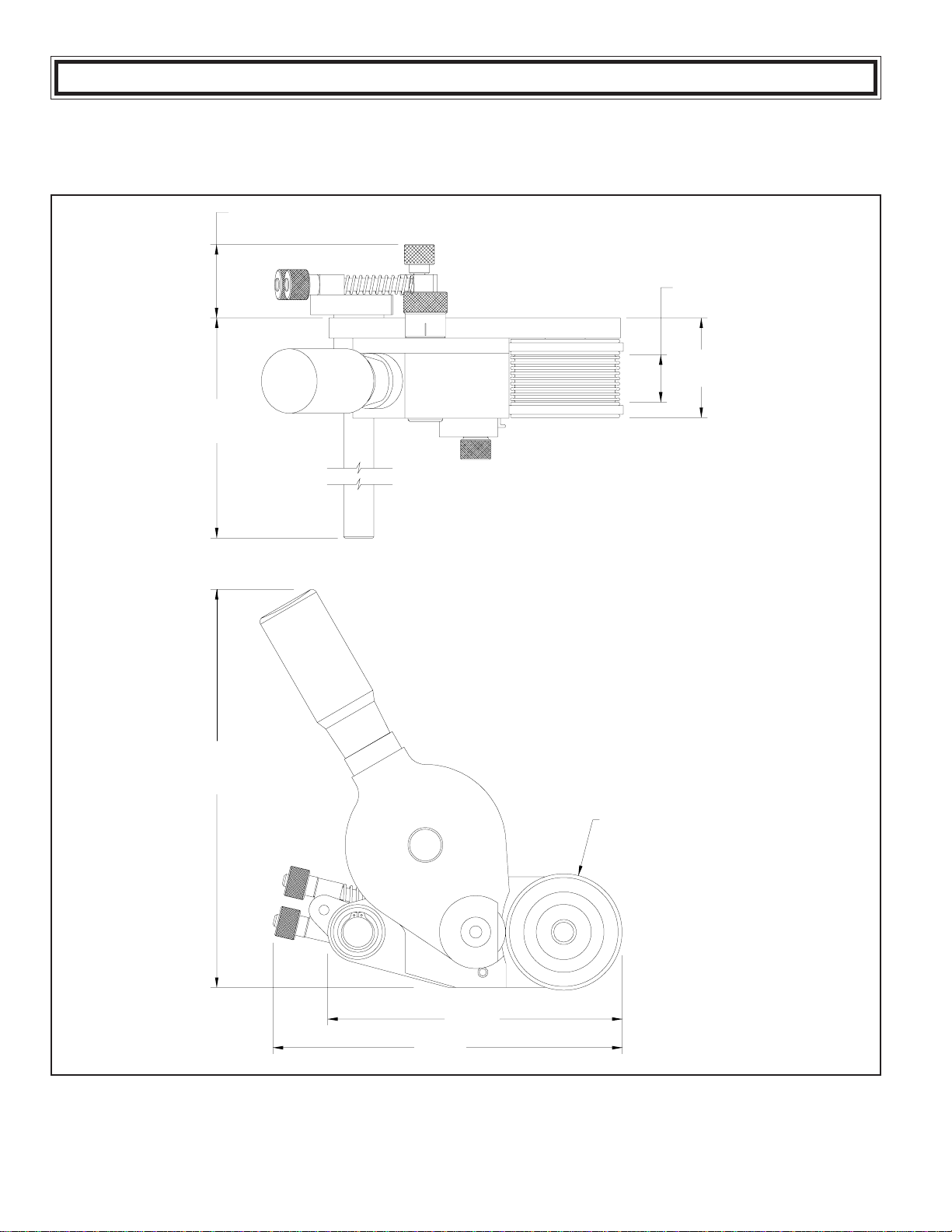
Universal MC-10NI Series User manual

1
NON-POROUS
MINI-CODER
ALL MODELS
NPMC-19197
UNIVERSAL STENCILING & MARKING SYSTEMS, INC.
P.O. BOX 871 - ST. PETERSBURG, FLORIDA 33731 USA
PH: (727) 894-3027 FAX: (727) 821-7944
STENCILING & MARKING SYSTEMS
OWNER’S MANUAL
INSTALLATION - OPERATION - MAINTENANCE

2
PREFACE
SPECIFICATIONS
MC-10NI Top Mount Series
MC-10 Side Mount Series
Indexing & Non-Indexing Models
Mounting Configuration
Printing Dies
Ink Rolls
QUICK START
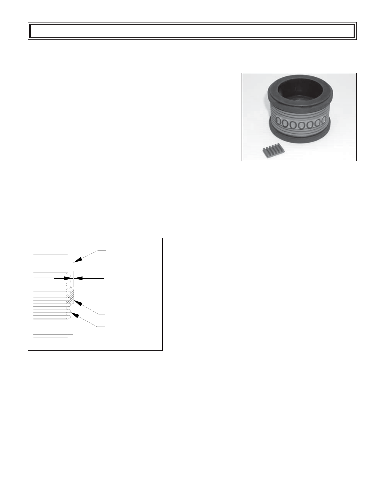
Installing the Pre-Inked Roll
Installing the Printing Dies
Adjusting the Ink Roll Eccentric
BASIC PRINCIPALS OF OPERATION
Inking System
Using the 4 oz. Reservoir Ink Cartridges
Selecting an Appropriate Ink
Ink Drying Time Considerations
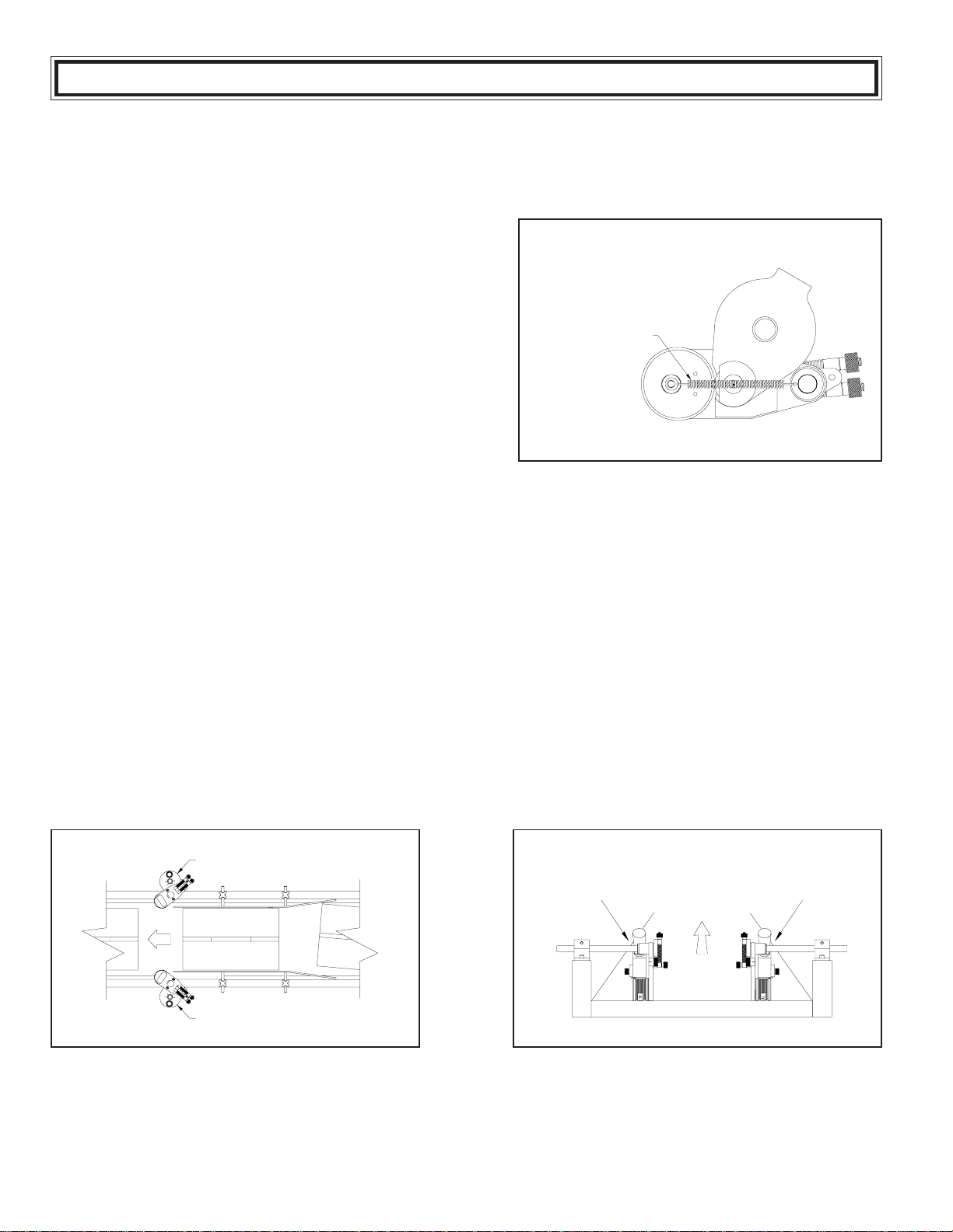
WEB PRINTING
Selecting a Place to Mount Your Coder
Special Web Printing Applications
Printing on Narrow Web Materials
Printing Directly on Master Rolls
CARTON PRINTING
Carton Alignment
DiePositioningforIndexingApplications
TRANSFERROLL/PRINTPRESSUREREADJUSTMENT
Adjusting the Transfer Roll Pressure
AdjustingPrintingPressure
MAINTENANCE
Pre-InkingaNewRoll
CleaningtheTransfer Roll
Cleaning the Coder
CleaningthePrintingDies
PARTSLIST&DIAGRAMS
IMPORTANT NOTE
UNIVERSAL products are manufactured to exacting standards and every available step has been taken to
assure your complete satisfaction. It is most important that the instructions contained in this manual are read
and carefully followed for best results. Failure to do so may result in unsatisfactory performance, damage to the
equipment and personal injury. TABLE OF CONTENTS 3
4
4
5
6
6
7
8
9
9
12
13
14
14
14
15
16
17
18
19
19
19
20
20
22
24
24
25
26
26
27
27
28
29
○○○○○○○○○○○○○○○○○○○○○○○○○○○○○○○○○○○○○○○○○○○○○○○○○○○○○○○○○
○○○○○○○○○○○○○○○○○○○○○○○○○○○○○○○○○○○○○○○○○○○○○○○○○○○○○
○○○○○○○○○○○○○○○○○○○○○○○○○○○○○○○○○○○○○○○○○○○
○○○○○○○○○○○○○○○○○○○○○○○○○○○○○○○○○○○○○○○○○○○○
○○○○○○○○○○○○○○○○○○○○○○○○○○○○○○○○○○○○○○○○
○○○○○○○○○○○○○○○○○○○○○○○○○○○○○○○○○○○○○○○○○○○○○
○○○○○○○○○○○○○○○○○○○○○○○○○○○○○○○○○○○○○○○○○○○○○○○○○○○○
○○○○○○○○○○○○○○○○○○○○○○○○○○○○○○○○○○○○○○○○○○○○○○○○○○○○○○
○○○○○○○○○○○○○○○○○○○○○○○○○○○○○○○○○○○○○○○○○○○○○○○○○○○○○○○
○○○○○○○○○○○○○○○○○○○○○○○○○○○○○○○○○○○○○○○○○○○
○○○○○○○○○○○○○○○○○○○○○○○○○○○○○○○○○○○○○○○○○○○○
○○○○○○○○○○○○○○○○○○○○○○○○○○○○○○○○○○○○○○○○○
○○○○○○○○○○○○○○○○○○○○○○○○○○○○○○○○○○○○○○○○○
○○○○○○○○○○○○○○○○○○○○○○○○○○○○○○○○○○○○○○○○○○○○○○○○○○○
○○○○○○○○○○○○○○○○○○○○○○○○○○○○○○○○○○○○
○○○○○○○○○○○○○○○○○○○○○○○○○○○○○○○○○○○○○○○○○○○
○○○○○○○○○○○○○○○○○○○○○○○○○○○○○○○○○○○○○○○○○
○○○○○○○○○○○○○○○○○○○○○○○○○○○○○○○○○○○○○○○○○○○○○○○○○○○○○○
○○○○○○○○○○○○○○○○○○○○○○○○○○○○○○○○○○○○○
○○○○○○○○○○○○○○○○○○○○○○○○○○○○○○○○○○○○○○○○
○○○○○○○○○○○○○○○○○○○○○○○○○○○○○○○○○○○○○○○○
○○○○○○○○○○○○○○○○○○○○○○○○○○○○○○○○○○○○○○○○○
○○○○○○○○○○○○○○○○○○○○○○○○○○○○○○○○○○○○○○○○○○○○○○○○○○○
○○○○○○○○○○○○○○○○○○○○○○○○○○○○○○○○○○○○○○○○○○○○○○○○○
○○○○○○○○○○○○○○○○○○○○○○○○○○○○○○○○○○○○
○○○○○○○○○○○○○○○○○○○○○○○○○○○○○○○○○○○○○○○○○○○○○○○○○○○○○○
○○○○○○○○○○○○○○○○○○○○○○○○○○○○○○○○○○○○○○○○○○○○○○
○○○○○○○○○○○○○○○○○○○○○○○○○○○○○○○○○○○○○○
○○○○○○○○○○○○○○○○○○○○○○○○○○○○○○○○○○○○○○○○○○○○
○○○○○○○○○○○○○○○○○○○○○○○○○○○○○○○○○○○○○○○○○○○○○○○○
○○○○○○○○○○○○○○○○○○○○○○○○○○○○○○○○○○○○○○○○○○○○
○○○○○○○○○○○○○○○○○○○○○○○○○○○○○○○○○○○○○○○○○○○○○
- LIMITED WARRANTY -
UNIVERSAL Non-Porous Mini-Coders are guaranteed to be free from defects in materials and workmanship for a
period of 90 days from the date of purchase. Components found to be defective during this time will be repaired free of
charge if returned to the factory. Damage resulting from use of improper inks, improper installation, or operation is not
covered under the scope of this warranty. For warranty service please contact our Customer Service Department.
○○○○○○○○○○○○○○○○○○○○○○○○○○○○○○
○○○○○○○○○○○○○○○○○○○○○○○○○○○○○○○○○○○○○○○○○○○○○○○○

3
Printing on non-porous materials has always been a major problem in industrial applications. The high degree of
maintenance required to keep conventional coders operating with solvent based inks has made many compa-
nies opt for manual marking as a cost effective alternative. With UNIVERSAL Non-Porous Coders, printing on
non-porous materials can be accomplished with the same relative ease as printing on porous materials. This
breakthrough in Non-Porous coder design opens up in-plant printing opportunities which previously were re-
garded as too costly to consider.
Inksused toprint onporous materialsdry throughabsorption intothe materialbeing printed.Inks usedto printon
non-porous materials dry through the rapid evaporation of the ink solvents after the print is applied. Since the ink
solvents must evaporate very rapidly on the printed material, they also evaporate very rapidly from the ink rolls
and ink wells of conventional coders therefore requiring constant maintenance.
Theproprietary design oftheUNIVERSAL Non-PorousInkingSystem effectively eliminatestherapid evaporation
of the ink solvents from the ink roll and additionally provides for convenient automatic re-inking of the roll without
interruptingthe printing process. Aftermanymonths ofdesignengineering andfieldtesting, theNon-porousMini-
Coder is both simplistic in design and extremely effective in operation. The relatively low cost of this system
makes in-plant printing of all types of non-porous materials a practical reality. The following pages of this manual
explainthe installation, operationandmaintenance ofNon-PorousMini-Coder and arethekey totroublefree non-
porous printing.
The specification section includes drawings with the basic dimensions of the coders, the net weights, maximum
die capacities, maximum print width and print drum circumferences. This section also lists the specifications for
the printing dies and an explanation of the Indexing and Non-Indexing models and the various mounting configu-
rations.
PREFACE
QUICK START
PAGES 9 THRU 15
This manual was written with a full understanding that very few people like to read manuals or have
the time to do so. To accommodate those who have little time to spare, we have included a Quick
Start section which will get your coder operating in just a few minutes.
To keep your coder operating properly, it is important to read and understand the Basic Principles of
Operation section which explains the basic operation of the Non-Porous Inking System.
CODER SPECIFICATIONS
Universal Non-Porous Mini-Coders are shipped from the factory, fully assembled and adjusted for the specific
mounting configuration indicated by the coder part number and description. The only additional preparation
required before putting the coder into operation is to install a pre-inked ink roller, install the printing dies, and
mount the coder on your production equipment.

4
SPECIFICATIONS
NON-POROUS MINI-CODER SPECIFICATIONS
MC-10NI TOP MOUNT SERIES
ModelShown: MC-10NI-NPRT
1.82
(46mm)
11.40
(290mm)
1.18
(30mm)
(63mm)
2.48
2.90
7.33
8.69
(74mm)
(186mm)
(221mm)
9.89
(251mm)
NET WEIGHT: 4 LBS. - 10 OZ. (2.10 KG.)
MAXIMUMDIESIZE - US STANDARD: 7/8” (8RIBS)X8-3/8” LENGTH
MAXIMUMDIE SIZE -METRICCODERS ONLY: 23.8MM(7RIBS) X 212.7MMLENGTH
PRINTDRUMCIRCUMFERENCE: APPROXIMATELY9.0"(228MM) MEASUREDAT DIE FACE

5
SPECIFICATIONS
NON-POROUS MINI-CODER SPECIFICATIONS
MC-10 SIDE MOUNT SERIES
ModelShown: MC-10-NPLS
4.20
107mm
11.40
290mm
1.18
30mm
2.60
66mm
2.90
74mm
7.33
186mm 8.69
221mm
3.98
101mm
NET WEIGHT: 4 LBS. - 5 OZ. (1.96 KG.)
MAXIMUMDIESIZE - US STANDARD: 7/8” (8RIBS)X8-3/8” LENGTH
MAXIMUMDIE SIZE -METRICCODERS ONLY: 23.8MM(7RIBS) X 212.7MMLENGTH
PRINTDRUMCIRCUMFERENCE: APPROXIMATELY9.0" (228 MM) MEASUREDAT DIE FACE

6
Non-indexing coders have print drums which simply rotate on bearings with no spring return mechanism.
These coders normally used for web printing applications where the print drum stays in contact with the web at
all times. If used in carton printing applications, when the trailing edge of a carton passes the coder, the print
drum rotation stops at a random position. When the next carton engages the print drum, the code will begin
printing at a random position relative to the leading edge of the carton and repeat the code every 9.1" down the
length of the carton.
Themounting configurationof acoderis determinedby howthe machine isdesigned tobe mounted inrelation to
the product and its movement. All references to mounting configuration are made as though you are viewing the
production line with the product moving away from you. Universal Mini-Coders are available from the factory in 4
different mounting configurations as shown in Figures 2 and 3.
INDEXING AND NON-INDEXING MODELS
MOUNTING CONFIGURATION
Note: Due to the asymmetrical design of the Inking System on the Non-Porous Mini-Coder, the mounting con-
figurations are not field convertible and must be properly specified when ordering.
Universal Non-Porous Mini-Coders are available in both indexing and non-indexing models.
Indexingcoderscontainaprintdrumspringreturnmecha-
nism which provides print registration capabilities when
carton printing (see Figure 1). As the trailing edge of a
carton passes the coder, the print drum automatically ro-
tates back to the same starting or “home” position. There
must be adequate space between cartons at any given
line speed for this mechanism to work properly. Printing
with an indexing coder will allow the imprint on each car-
ton to be registered in the same position relative to the
leading edge of the carton. The code will repeat every
9.1" down the length of the carton.
FIGURE2
FIGURE1
FIGURE3
PRINT DRUM
INDEXSPRING
RIGHTHAND
SIDEMOUNT
LEFTHAND
SIDEMOUNT
LEFTHAND
TOPMOUNT RIGHTHAND
TOPMOUNT
SPECIFICATIONS

7
FIGURE5
BEARERRING
.007” - .008”
PRINTINGDIE
DRUMCOVER
FIGURE4
RIBtype® PRINTING DIES
The dies are manufactured to precision thickness toler-
ances which are very critical to the performance of these
coders. When installed, the face of the printing die should
extend only .007" - .008" beyond the radius of the Bearer
Rings as shown in Figure 5. Using dies that do not meet
thedesign specificationswillresult inpoor print qualityand
possible damage to the transfer roll.
Although there are several competitive rib backed die sys-
tems available, it is very important to note that they are not
all made to the same rib spacing or thickness specifica-
tions and are not interchangeable.
Universal also offers Metric RIBtype® die systems for use in countries where metric character sizes are the
standard. The Metric dies are thicker and the rib spacing differs slightly from the standard printing dies therefore
the two versions are not compatible. To accommodate the differences, the print drums for Metric dies are
machined to a slightly different diameter from the U.S. versions.
The coder model numbers on Metric coders will have a “-T” suffix and the Metric Drum Covers have a distinct
pinkcolor.
CODER MODELS DESIGNED FOR METRIC RIBtype® PRINTING DIES
Printing dies are also available in “logo” form in which a complete text message, company logos or trademarks
are produced on a single piece of rib backed rubber. These “logo” dies are photographically reproduced from
black and white art work. Due to their unitized construction, these dies generally produce better print quality and
are much faster to change in the field. For details on ordering custom logo dies, please contact our Customer
Service Department.
UniversalNon-Porous Coders aredesignedto useRIBtype® print-
ing dies which have a molded rib backing. The ribs on the back of
the die snap into mating ribs in the Drum Cover on the print drum
as shown in Figure 4.
The standard printing dies are available in sets with many sizes
and character styles. The sets are a combination of individual al-
phabeticandnumericcharacters or insetscontainingnumericchar-
acters only. These character sets or “sorts” can be used to make
up text messages and code numbers as necessary.
SPECIFICATIONS

8
Universal offers two ink roll options for the Non-Porous Mini-Coders - each with unique characteristics which will
help determine the suitability for a specific printing application. The coders are designed to accommodate both
types of ink rolls without modification. A detailed review of your printing requirements will determine the best
choice of ink rolls for your particular application.
Universal’s XF Neoprene Ink Rolls are a re-inkable roll which
canbe used with a variety of alcohol or glycol base inks. These
rolls are normally supplied in a dry condition from the factory
and require pre-inking prior to mounting on the coder. During
productionprinting, whenthe ink capacityof theroll isdepleted,
installing a 4 Oz. Reservoir Ink Cartridge in the coder’s reser-
voir Bottle Port will re-ink the roll automatically as production
continues.
Universal’s Type MT Ink Rolls are disposable pre-inked rolls
whichare available inavariety offastdrying colors. TheMTInk
Rolls provide excellent color density and adhesion on most
materials and an average yield of just under 500,000 impres-
sions before replacement is necessary. Since these rolls are
notre-inkable, allreferencesin themanual regarding theuse of
4 Oz. reservoir Ink Cartridges should be disregarded when us-
ing these rolls on your coder. The ability to operate the coder
without a Reservoir Ink Cartridge makes the MT Rolls particu-
larlywell suitedfor applicationsrequiring printing onthe bottom
of web materials.
TheTypeMTInk Rollsprovide drying timesbetween 4- 7 secondsat 75Degree F.(24 Deg. C)ambient tempera-
tures. The added convenience and simplicity of using the Type MT Ink Rolls makes them an ideal choice when
production operators have little time to monitor the inking system.
XF NEOPRENE INK ROLLS
TYPE MT INK ROLLS
Inhigh speedwebprinting applications,Universal’s#100 Inksprovidedrying timesofapproximately 2seconds at
75 Degree F. (24 Deg. C) ambient temperatures. Many other inks, both dye and pigment based, can be used in
these ink rolls to meet the specific application requirements. Refer to the Basic Principles of Operation section
on Page 15 for more information on selecting an appropriate ink.
INK ROLLS
FIGURE6
FIGURE7
SPECIFICATIONS

9
The ink roll you install on the coder must be properly pre-inked. If your coder was supplied with a dry XF
Neoprene ink roll, refer to the Maintenance Section page 25 for inking instructions.
Warning: Non-Porous inks contain flammable solvents. Do not smoke or handle these rolls in the
presence of sparks or open flames. Inks will also stain clothing, furniture, carpeting and your hands.
Rubber gloves should be worn during the following procedures.
INSTALLING THE PRE-INKED ROLL
This moves the Ink roller axle away from the Transfer
Rolland enablestheink rolltobe installedwithoutinter-
ferencewiththe Transfer Roll duringreassemblyof the
inking system.
The Cover Retaining Knob holds the entire inking sys-
temtogetherand otherpartsmay fallfreefromthecoder
if not held securely when this knob is removed.
TheKnurledDriveWheelCoverisveryloosefitting. Note
that the flat on the side of the Drive Wheel Cover is
alignedtowardstheprintdrum. Duringreassembly,this
must be replaced in the same position.
Rollers that have been pre-inked at the factory are normally slightly oversaturated with ink to compensate for
potential solvent loss during shipping and storage. If you received a pre-inked ink roll with your coder, it is
importantto examinethe rollpriorto installation. The ink roll should be thoroughly saturated with ink but not
dripping wet. Excess ink can be easily removed by lightly rolling the ink roll across a clean piece of absorbent
paper.
1 - To install the pre-inked roll, first turn the Ink Roll Ec-
centric Adjusting Knob “A” to the “MIN” position.
2 - While holding the Drive Wheel Cover “B” in place,
remove the knurled Cover Retaining Knob “C” by turn-
ing it counterclockwise.
3 -Hold Inking System Cover “D” in place and remove
Knurled Drive Wheel Cover “B”.
FIGURE8
FIGURE9
FIGURE10
QUICK START

10
TheKnurledDriveWheelrestsontopoftheTransferRoller
andis installedover 3stainless drivepins whichprotrude
through 3 mating holes in the Drive Wheel. This is a
closetolerance fitand therewillbesomeresistance from
theengagementwith the rubberBearerring on the Print
Drumwhenthis is removed. Aslightrotationor wiggling
actionwillmake removal easier.
4 - Remove the Knurled Drive Wheel “E”.
Rolls which have been pre-inked at the factory are typi-
cally over saturated with ink to compensate for potential
solvent loss during shipping and storage. Installing an
over saturated roll on the coder will result in ink leakage
from the Inking System and in extreme cases may dam-
agethe ballbearingsintheTransfer Roll. Whenthe roller
is installed, it must be thoroughly saturated with ink but
you should not be able to see any liquid ink on the sur-
face of the roll. If necessary, blot excess ink from the
sidesofthe roll with adrypaper towel before installation.
The Transfer Roll Surface is a finely engraved Delrin
plasticmaterialwhich can be easily scratched. When
assembled, the Transfer Roll resides in a very close
fittingcavityin Inking System Cover. Carefully pulling
theInkingSystem Cover directlyawayfrom the Base-
plate until it clears the Transfer Roll will prevent dam-
ageto the TransferRollsurface.
Keeping ink off your gloves at this stage will prevent
contaminationof the externalpartsof thecoderduring
rollinstallation
5 -Carefully pull the Inking System Cover “D” directly
away from the Inking System Baseplate “F”. Do not
let the cover drag across the surface of the Trans-
fer Roller “G”.
6 - Put on a pair of rubber gloves and remove the pre-
inked ink roller from the storage container by insert-
ing a small rod (a pencil works nicely) in the center
of the core.
7 -Inspect the roll for excess surface wetness. Remove
any excess ink by rolling the roll lightly over a piece
of absorbent paper.
FIGURE11
FIGURE12
FIGURE13
FIGURE14
QUICK START

11
Whenthis step iscomplete,remove the rubberglovesto
prevent ink contamination with the external parts of the
coder.
Whilehandlingthe ink rolls, solvents willevaporatefrom
the rolls very rapidly at normal room temperatures. The
InkingSystem Covermustbe replacedquickly toprevent
solventloss.
A slight wiggling action or rotation of the Drive Wheel will
help overcome the resistance caused by contact with the
rubberBearer ringon thePrint Drum. Thetopsofthestain-
lesspinswill be flush withthetop of the Drive Wheelwhen
seatedproperly.
HoldtheDrive Wheel CoverandInking System Coverin
place.
8 - Install the ink roll on the Ink Roll Axle “H” by aligning the
end of the rod or pencil with the end of the axle and push-
ing the roll onto the axle.
9 -Immediately replace the Inking System Cover “D” by care-
fully guiding the cover over the Transfer Roll “G”. Try
not to let the cover contact the surface of the Transfer
Roll to prevent scratching. Make sure the Cover is
seated properly against Baseplate “F”.
10 -Replace the Knurled Drive Wheel “E” by aligning the 3
small holes with the 3 stainless drive pins on the top of
the Transfer Roll “G” and pressing the Drive Wheel onto
the Transfer Roll.
11- Replace the Drive Wheel Cover “B” and rotate it into
position with the flat edge directly facing the Print Drum.
FIGURE15
FIGURE16
FIGURE17
FIGURE18
QUICK START

12
Characters which have only a 2 or 3 rib backing do not
have the stability of the larger sizes when snapped into
the drum cover. Adding the rib backed type blocks on
either size of the code will provide added stability. The
Type Blocks are not as thick as theTypeandwillnotpick
upinkfrom the TransferRoll.
The Cover Retaining Knob should be just tight enough
tokeeptheInkingSystemAssembly together and pre-
venttheDriveWheelCoverfromrotatingoutofposition.
INSTALLING THE PRINTING DIES
Individualcharacter codes ortextmessages are installed
in a mirror image of normal written text. In other words
install in a right to left direction as shown. When printed,
codes or text installed in this orientation will print in nor-
mal left to right order.
Tip: To make die installation easier, moisten a sponge with water containing a small amount of liquid
detergent. Lightly moisten the back of the printing die and then immediately press the die into the drum
cover. Do not apply too much liquid or the dies will slip during printing. Note: Do not apply silicone, oil
or any other lubricating agent to the rib backing or the dies will not hold properly during printing.
12 - Replace the Cover Retaining Knob “C” and lightly
tighten. Do not over tighten this knob or you may bend
the top of the Drive Wheel Cover “B” and cause it to
bind against the Knurled Drive Wheel.
1 - Install the Printing Dies “I” on the Print Drum “J” by
aligning the ribbed backing on the dies with the mat-
ing covering on the Print Drum and pressing firmly
until they are completely engaged. It is best to install
the dies as close to the middle of the pint area on the
Print Drum as possible.
2 - When using small individual characters to make up a
code message, use the Type Blocking Kit “K” included
with your coder to support the leading and trailing ends
of the type as shown.
FIGURE19
FIGURE20
FIGURE21
QUICK START

13
ADJUSTING THE INK ROLL ECCENTRIC
As soon as you can see complete ink coverage on the die faces, stop rotating the eccentric. Proper adjustment
will normally be reached when the reference line on the Eccentric is somewhere between the 2 and 3 dial
position.
This adjustment procedure brings the Ink Roller into contact with the surface of the Transfer Roller which in turn
applies the ink to the face of the printing dies. Do not rotate the Ink Roll Eccentric Knob further than necessary
towards the “MAX” position or the excess contact pressure will squeeze ink out of the ink roll and may cause
dripping inside the cover.
FOR MOUNTING INSTRUCTIONS
REFER TO THE APPROPRIATE SECTION
FOR YOUR APPLICATION
WEB PRINTING - PAGE 17
CARTON PRINTING - PAGE 21
With the printing dies installed on the print drum, manu-
ally rotate the print drum continuously in one direction
while slowly rotating the Ink Roll Eccentric Adjusting Knob
“A” from the “MIN” towards the “MAX” position. Turn the
Eccentric Knob in small increments and observe the face
of the printing dies “I” for signs of ink between each ad-
justment.
FIGURE22
QUICK START

14
THE NON-POROUS INKING SYSTEM
Inks designed for printing on non-porous surfaces contain very fast drying alcohol solvents, a component to
impart color which can be either a liquid “dye” or a finely ground solid or “pigment”, and a resin material which
binds the color medium to the material surface. When the printed marks are applied by the coder, the solvents
rapidly evaporate from the surface of the material leaving only the dried resin and color.
Preventing rapid solvent loss from the inking system, which would cause the coder to stop printing, has tradition-
allybeen averydifficult task. Universal’spatentedNon-Porous InkingSystemdesign hasovercome this problem
by enclosing all of the inking system components in a tightly sealed housing. This unique design offers the
capabilities of a flexographic printer without the limitations associated with having an open well of ink. The
advantages of this design include minimal maintenance requirements, unrestricted mounting configurations and
the ability to rapidly change ink colors.
The inking system is comprised of two main components
as shown in Figure 23 The ink roll serves as a reservoir
for the ink, and a transfer or “anilox” roll transfers the ink
fromthe ink rollto the faceof the printingdies. Toprevent
the loss of ink solvent through evaporation, these rolls
are mounted in separate precision machined cavities in
a sealed aluminum housing. The integrity of the housing
is such that the system can be left idle for days without
risk of the ink roll drying out.
Theinkrollisinstalledonan eccentric mounted axlewhich
enablesthe rollto beadjusted intocontact withthe trans-
fer roll. The surface of the transfer or “anilox” roll is finely
engraved with thousands of microscopic cavities which
picks up ink from the ink roll and transfers it to the sur-
face of the printing dies. Since the transfer roll applies a
very thin film of ink to the die face, the printed marks dry
veryrapidly.
USING THE 4 OZ. RESERVOIR INK CARTRIDGES
Note: The MT Ink Roll is disposable by design and is not to be used with the 4 oz. ink cartridge. When the ink
is depleted from the MT Ink rolls they are to be discarded.
It is important to note that the Reservoir Ink Cartridge shown in Figure 23 is not considered to be an integral part
of the inking system but is used only to re-ink the XF neoprene ink roll when needed. The 4 Oz. Reservoir Ink
Cartridges should be installed only after the ink supply in the XF neoprene ink roll has been depleted
and the printed marks indicate a need for more ink. Depending on the amount and size of the text being
printed and number of imprints being applied per hour, the ink capacity of the XF neoprene ink roll may last
anywhere from 1 hour to several days of continuous operation. Installing a 4 ounce Reservoir Ink Cartridge
prematurely may result in over saturation of the XF neoprene ink roll and flooding of the inking system.
FIGURE23
4OZ.RESERVOIR
INKCARTRIDGE
PLASTICBALL
TRANSFER
ROLL
INKROLL
ECCENTRIC
BASIC PRINCIPLES OF OPERATION

15
SELECTING AN APPROPRIATE INK
When a Reservoir Ink Cartridge is threaded into the bottle port, the plastic ball in the cartridge comes into contact
with the surface of the neoprene ink roll. When the ink roll rotates during the printing operation, a thin film of ink
is transferred from the reservoir cartridge onto the surface of the ink roll. The printed impressions will improve
within a few seconds after installation of the cartridge. When the printing operation is stopped, the Reservoir Ink
Cartridge automatically stops feeding ink to the roller to prevent over saturation during idle periods.
The knurled drive wheel shown in Figure 24 sits on top of
the transfer roll and is engaged by three stainless steel
drive pins. The knurled face of the drive wheel runs in
contact with a bearer ring on the print drum. When the
print drum starts to turn, the knurled drive wheel rotates
the transfer roll at the exact surface speed of the die face.
Keeping these two surfaces running at a synchronous
speed ensures a uniform coating of ink on the die face
and extends die life.
Universal’s Non-Porous Inking System is compatible with a wide range of alcohol base marking inks. Although
weoffer avariety ofinks forspecific applications,you arenot restrictedto usingonly Universalbrand inks. When
selecting inks from other manufacturers however, it is your responsibility to make sure the inks are compatible
with the coder.
Dye base inks contain liquid color which is translucent and will provide good color contrast only on light colored
materials. Theseinks aregenerally fasterdrying than pigmentedinks andnormally produceless residue buildup
on the transfer roll and printing dies, thus requiring less frequent cleaning of the coder. Although dye base inks
are normally the easiest to use, they will fade more rapidly than pigmented inks when exposed to direct sunlight.
Pigmented inks contain finely ground solids which are opaque, providing much greater color contrast when
marking on dark colored surfaces. These inks also resist fading when exposed to direct sunlight. Pigmented
inks have a tendency to build up on the surface of the transfer roll and the die face more rapidly than dye base
inks and will generally require more frequent cleaning of these parts.
Thefirst stepin selecting anappropriate ink,is todetermineif theink willbondto thesurface ofthe material being
printed and provide acceptable color contrast. It is normally recommended that inks be test printed on the
material being marked with a rubber stamp to determine if the resulting marks are acceptable. Please note that
when testing inks with a rubber stamp, the drying times will generally be much slower than when the inks are
appliedwith the Non-Porous Mini-Coder.
It is also extremely important to test the affect of other manufacturer’s ink on the XF Neoprene ink roll.
Since the ink roll must fit into a precision machined cavity in the inking system housing with little clearance,
swelling of the roll, in reaction to non-compatible solvents in the ink, could cause serious problems with the
performance of your coder. The dry XF neoprene ink roll measures 3.425" (86.99 mm) OD. After thoroughly
saturating the ink roll with ink, the roll should not exceed 3.500" (88.90 mm) OD.
FIGURE24
TRANSFER
ROLL
INKROLL
KNURLED
DRIVEWHEEL
PRINTINGDIE
BEARER
RING
BASIC PRINCIPLES OF OPERATION

16
INK DRYING TIME CONSIDERATIONS
Dependingon the specific characteristics of the printing application, someconsideration needsto begiven tothe
drying time of the ink and its suitability for the application. Printing on a plastic film in an intermittent motion Form
and Fill Machine may require a slower drying ink formulation than that recommended for high speed continuous
web printing applications. Although extremely fast drying inks are normally specified by customers in all applica-
tions, the ink must be suitable for the specific application or it will not perform properly in the coder.
Universal#100 inkis an extremelyfast dryingformu-
lation and is normally recommended for continuous
motion web printing applications. In these applica-
tions, the ink must dry very rapidly on the material to
preventdownstream transferto idlerrolls. Whenthe
print drum is rotating at high speeds, the dies rotate
pasttheTransfer Rollwhere inkis applied andwithin
milliseconds the die face contacts the surface of the
material being printed and the impression is trans-
ferred. (Refer to Figure 25)
When printing on very slow moving web materials, the print drum rotates at much slower speeds. As a result,
when the dies rotate past the Transfer Roll and the ink is applied, it may take several seconds for the dies to
contact the web. Since the solvents in the #100 Inks evaporate very rapidly at normal room temperatures (even
from the die faces), the die faces may be dry before contact with the web material. In these applications, a
slightly slower drying ink formulation would be necessary to ensure that the ink remains wet on the die faces until
they contact the web material.
When the coder is installed on a Form and Fill machine, the plastic film may move at fairly high speed when
pulled from the supply roll but it stops for a period of time during the product fill cycle. In these applications, if the
die face has already rotated passed the Transfer Roll and picked up ink and the web motion stops for several
seconds, a very fast drying ink like the #100 will flash off the die face before the web motion resumes. It is
therefore necessary to take into consideration the cycle rate of the particular machine when selecting an ink.
FIGURE25
TRANSFERROLL
DIEFACE
WEBMATERIAL
BASIC PRINCIPLES OF OPERATION

17
Toeliminate thisproblem,if idlerroller positions
are not adjustable, a slight undercut in the face
of idler roller “B” where the printed marks pass
under the roll, will prevent the wet marks from
touchingthe faceof theidler. Generally theun-
dercut in the idler roller needs to be only .020" -
.030" deep and slightly wider than the printed
marks as shown in Figure 27
This section applies to the installation of the Non-Porous Mini-Coders for printing on continuous web materials
such as plastic films, rubber sheeting, metals and other extruded materials.
Careful consideration should be given to selecting an appropriate area in the production line for installation of the
coder. Since the coders are friction driven by the moving web of material, a primary factor is to select an area
wherethe positionof thewebmaterial isaccurately controlledand preferably supportedby anidler orguideroller
on the underneath side as shown in Figure 26.
The only real consideration with respect to
the attitude of the coder frame is that the 4
oz. reservoir ink cartridge (when installed)
should be kept as near as possible to a ver-
tical position with the plastic ball pointing
down. This will ensure proper ink feed from
the 4 oz. cartridge to the ink roll. When dis-
posable Type MT Ink Rolls are used on the
coder, 4oz.Reservoir Ink Cartridgesarenot
used and therefore the coder can be
mounted in any convenient attitude. When
installing the coder, the print drum axle of
thecodershouldbeinparallelalignmentwith
the idler roll and the print drum should con-
tact the web at the point where the web is
tangenttotheidler roll andsolidlysupported.
It is also important to note that the distance “C” between idler roller “A” and idler roller “B” should be adequate so
that at the maximum web speed, the ink will dry before the printed marks contact idler roller “B”. If distance “C”
is not adequate for the drying time of the ink used, a ghost image transfer of the marks may be overprinted on the
web by idler roller “B”.
FIGURE27
FIGURE26
MOUNTING
COLUMN
4OZ.RESERVOIR
INKCARTRIDGE
PRINTDRUM
IDLERROLL “A”
IDLERROLL“B”
WEBTRAVEL
15DEG.
IDLERROLL
WETIMPRINT
UNDERCUT
.020” - .030”
“C”
WEB PRINTING

18
In high speed web applications, the distance the web travels at a given speed in 2-3 seconds can be substantial.
It is important to note that when the printed web is tightly rewound, the additional pressure applied to the printed
marks can increase the possibility of a ghost image transfer of the ink to the back of the web.
If this situation occurs and the web speed cannot be slowed down to allow more drying time, air blowers can be
used to direct heated air on the printed marks to accelerate drying. Preheating the web material slightly with hot
air before printing can also be an effective method to decrease the drying time. If either of these techniques are
used, it is recommended that the hot air blowers be electrically tied into the web feed motor energizing circuit.
This will ensure that the blowers are turned off automatically if the web is stopped.
MOUNTING THE CODER
1 - After determining the best location to mount
the coder, install the supplied mounting bracket
(Figure 28) on a rigid surface using two 3/8" di-
ameter bolts, nuts, washers and lock washers
(not supplied). Be sure that mounting column
of the coder is parallel to the idler roll.
2 - Insert the mounting column into the mounting
bracket and allow the print drum to pivot into
contact with the idler roll. Do not tighten the
bracket clamping screw at this time.
3- Using an adjustable wrench, grip theCamBlock
(Figure 29) and rotate it approximately 10-15 de-
grees to compress the Tension Springs. While
holding the Cam Block in this position, tighten
the Mounting Bracket Clamping Screw.
This procedure is used to adjust the contact pres-
sure which the print drum exerts against the web.
Onlyenough pressure shouldbe applied toensure
positive friction drive of the print drum. Excessive
contactpressurewill impose unnecessarydragon
the web and may result in poor print quality.
DO NOT INSTALL A 4 oz. RESERVOIR INK CARTRIDGEAT THIS TIME. The coder is designed to print using
the ink contained in the pre-inked ink roll. Since a freshly saturated Ink Roll was just installed on the coder, the
system will have plenty of ink. Installing a 4 oz. Reservoir Ink Cartridge immediately will result in over
saturation of the ink roll and flooding of the Inking System. The 4 oz. Reservoir Ink Cartridge should not be
installed until most of the ink is consumed from the ink roll and the print quality shows signs that more ink is
needed.
FIGURE28
FIGURE29
IDLER ROLL 3/8”BOLTS
MOUNTING
BRACKET
CLAMPING
SCREW
MOUNTINGCOLUMN
PRINT DRUM
TENSION SPRINGS
BASEPLATE
CAMBLOCK
30 DEG.
WEB PRINTING

19
In applications where the web material is too narrow for both bearer rings to contact the surface of the web,
contact with one bearer ring is acceptable. When the web is too narrow for even one bearer ring to contact the
web and still position the print as necessary, a custom made guide roller can often be utilized.
SPECIAL WEB PRINTING APPLICATIONS
PRINTING ON NARROW WEB MATERIALS
Usingthis approach,the guiderollmust bemachined witha
groovewhich willnotonly accuratelyguidethe webmaterial
and drive the guide roll but it must also keep the surface of
the web material flush with the surface of the guide roll
where the bearer rings make contact. (See Figure 30.)
Thismethodofmountingis generally moreappropriatewhen
the web material is extruded rubber or some similar mate-
rialwhich has a high coefficient of frictionsince itmust drive
boththe guide rolland the printdrum. Usinga customguide
roller which is driven by an external power source is cer-
tainly acceptable but it is generally rather costly since the
surface speed of the guide roller must precisely match the
speed of the web or smeared prints will result.
PRINTINGDIRECTLYONMASTERROLLS
Universal Non-Porous Mini-Coders can also be mounted on custom designed extension arms which will enable
them to print directly on the surface of a master roll of web material as it is unwound. This technique is frequently
used when conveniently positioned idler rolls are not available. In these applications, as the master roll of web
material decreases in size, the mounting arm pivots and keeps the print drum in constant contact with the
surface of the roll as shown in Figures 31 & 32.
Youwill notein Figure31 thatthe coderis mountedin an orientationwhich willrotatethe printdrum inthe reverse
direction of a normal web printing installation. This is an acceptable method of mounting the coder if it is more
convenient for installation on the parent equipment. In these installations, the weight of the coder is used to
supply printing pressure and typically the standard spring tension mechanism and mounting column are re-
moved. Custom mounting brackets and extension arms should be carefully designed to keep the coder in an
acceptable attitude when printing on a full roll of film all the way down to the smaller diameter of the core. For
more details on custom mounting systems, contact our engineering department.
FIGURE30
FIGURE31 FIGURE32
PRINT DRUM
BEARER RING
MODIFIED
GUIDE ROLLER
NARROW WEB
MATERIAL
GROOVE
CUSTOMEXTENSION ARM
CUSTOMMOUNTING
BRACKET
MASTERROLL
OF FILM CODER
EXTENSIONARM
MASTER
ROLL
WEBTRAVEL
PIVOTPOINT
WEB PRINTING

20
Printing on non-porous surfaces, such as waxed or varnished cartons, can be accomplished easily with Univer-
sal Non-Porous Mini-Coders. The selection of an appropriate place for installation on your conveyor line or other
packaging equipment is a very important consideration in the performance of your coder. The most important
factor to consider is carton alignment. To ensure print reliability and prevent damage to your coders, the cartons
must be accurately guided through the printing station by guide rails. If your conveyor is not equipped with guide
rails-theymust be installed beforeproceedingwithcoderinstallation.
CARTON ALIGNMENT
Proper alignment of the cartons as they pass the printing station is imperative as shown in Figure 33. Improper
alignment will produce poor print quality, poor print registration, and in extreme cases, could damage the ma-
chine.
UniversalNon-Porous Mini-Codersare spring loadedso thatthe printdrumswill pressagainst thecarton surface
on contact. This pressure is necessary to accomplish the friction drive rotation of the print drum and ensure
enough printing pressure to give you a sharp impression. The spring tension mechanism on the coder will also
compensate for slight variations in the width of the cartons without jamming the conveyor line. Excessive pres-
sure, caused by improperly guided cartons, will result in smudged impressions and could cause damage to the
spring tension mechanism.
FIGURE33
GUIDE RAILS
PROPERALIGNMENTIMPROPERALIGNMENT
CARTON PRINTING
This manual suits for next models
1
Table of contents
Other Universal Industrial Equipment manuals