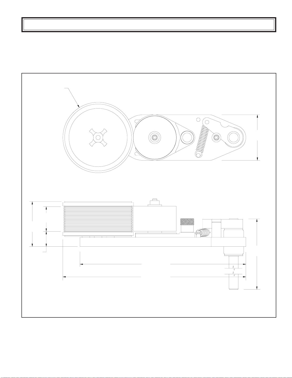
Universal MS-120NI User manual

POROUS
MIDSIZE CODERS
ALL MODELS
Pro Pack Solutions, Inc.
2421B Lance Court, Loganville, GA 30052
PH: (770) 554-1187
E-Mail: sales01@propacksolutions.com
Website: www.propacksolutions.com
MSP-12302
1
STENCILING & MARKING SYSTEMS
OWNER’S MANUAL
INSTALLATION - OPERATION - MAINTENANCE

2
PREFACE
SPECIFICATIONS
MS-120NI-LeftHandMount
MS-150NI-LeftHandMount
MS-180NI-LeftHandMount
MS-220NI-LeftHandMount
MS-250NI-LeftHandMount
MS-280NI-LeftHandMount
IndexingandNon-IndexingModels
MountingConfigurations
Printing Dies
InkRolls
Reservoir Roll Covers & 4oz. Reservoir Ink Cartridges
QUICK START
Pre-InkingMicrocell Rolls
InstallingthePre-InkedRoll
Installing the Printing Dies
Adjusting the Inking System
CODERINSTALLATION
CartonAlignment
Die Positioning for Indexing Coder Models
MAINTENANCE
Installing the Optional Reservoir Roll Covers
Installing the 4oz. Reservoir Ink Cartridges
Pre-Inking Neoprene & XF Neoprene Foam Rolls
Cleaning the Coder
Cleaning the Printing Dies
MOUNTINGCONFIGURATIONCONVERSION
Right-Hand & Left-hand Field Conversion
Changing Print Drum Sizes
PARTS DIAGRAMS & PARTS LISTS
IMPORTANT NOTE
UNIVERSAL products are manufactured to exacting standards and every available step has been taken to assure your
complete satisfaction. It is most important, however, that the instructions contained in this manual are read and carefully
followed for best results. Failure to do so may result in unsatisfactory performance, damage to the equipment and personal
injury.
- LIMITED WARRANTY -
UNIVERSAL PorousMidsizeCodersare guaranteedto befree fromdefects inmaterials andworkmanship fora periodof
90 days from the date of purchase. Components found to be defective during this time will be repaired free of charge if
returnedto thefactory.Damageresultingfrom useofimproperinks,improper installation,oroperation isnotcoveredunder
thescopeof thiswarranty. Forwarrantyservice pleasecontact ourCustomerService Department.
3
4
5
6
7
8
9
10
10
11
12
13
14
15
16
17
18
20
22
22
23
24
24
25
26
27
○○○○○○○○○○○○○○○○○○○○○○○○○○○○○○○○○○○○○○○○○○○○○○○○○○○○○○○○○
○○○○○○○○○○○○○○○○○○○○○○○○○○○○○○○○○○○○○○○○○
○○○○○○○○○○○○○○○○○○○○○○○○○○○○○○○○○○○○○○○○○
○○○○○○○○○○○○○○○○○○○○○○○○○○○○○○○○○○○○○○○○○○
○○○○○○○○○○○○○○○○○○○○○○○○○○○○○○○○○○○○○○○○○
○○○○○○○○○○○○○○○○○○○○○○○○○○○○○○○○○○○○○○○○○○
○○○○○○○○○○○○○○○○○○○○○○○○○○○○○○○○○○○○○○
○○○○○○○○○○○○○○○○○○○○○○○○○○○○○○○○○○○○○○○○○○○○
○○○○○○○○○○○○○○○○○○○○○○○○○○○○○○○○○○○○○○○○○○○○○○○○○○○
○○○○○○○○○○○○○○○○○○○○○○○○○○○○○○○○○○○○○○○○○○○○○○○○○○○○○○
○○○○○○○○○○○○○○○○○○○○○○○○○○
○○○○○○○○○○○○○○○○○○○○○○○○○○○○○○○○○○○○○○○○○○○
○○○○○○○○○○○○○○○○○○○○○○○○○○○○○○○○○○○○○○○○○○
○○○○○○○○○○○○○○○○○○○○○○○○○○○○○○○○○○○○○○○○○○
○○○○○○○○○○○○○○○○○○○○○○○○○○○○○○○○○○○○○○○○○○
○○○○○○○○○○○○○○○○○○○○○○○○○○○○○○○○○○○○○○○○○○○○○○○○
○○○○○○○○○○○○○○○○○○○○○○○○○○○○○○○○○○
○○○○○○○○○○○○○○○○○○○○○○○○○○○○○○○○
○○○○○○○○○○○○○○○○○○○○○○○○○○○○○○○○
○○○○○○○○○○○○○○○○○○○○○○○○○○○○○
○○○○○○○○○○○○○○○○○○○○○○○○○○○○○○○○○○○○○○○○○○○○○○
○○○○○○○○○○○○○○○○○○○○○○○○○○○○○○○○○○○○○○○○○○○
○○○○○○○○○○○○○○○○○○○○○○○○○○○○○○○○○○
○○○○○○○○○○○○○○○○○○○○○○○○○○○○○○○○○○○○○○○○○○
○○○○○○○○○○○○○○○○○○○○○○○○○○○○○○○○○○○○○○○○
○○○○○○○○○○○○○○○○○○○○○○○○○○○○○○○○○○○○○○○○○

3
The specification section includes drawings with the basic dimensions of the coders, the net weights, maximum
die capacities, maximum print width and print drum circumferences. This section also lists the specifications for
the printing dies and an explanation of the Indexing and Non-Indexing models and the various mounting con-
figurations.
PREFACE
CODER SPECIFICATIONS
The Universal Midsize Coder has been designed to print lot numbers, date codes, and text information on
cartons, web materials, and other conveyored products. Universal Midsize Coders are precision engineered to
give years of reliable service under the most demanding conditions.
Features Include:
•Indexing (spot printing) and non-indexing (continuous printing) models.
MS-120 print area is 1" x 12"
MS-150 print area is 1" x 15"
MS-180 print area is 1” x 18”
MS-220 print area is 2" x 12"
MS-250 print area is 2" x 15"
MS-280 print area is 2” x 18”
•Inter-changeable print drums provide additional versitility.
QUICK START
PAGES 14 THRU 17
This manual was written with a full understanding that very few people like to read manuals or have the
time to do so. To accommodate those who have little time to spare, we have included a Quick Start
section which will get your coder operating in just a few minutes.
• Optionalreservoirinking system which automatically feedsinkto the ink roll duringoperation. Patenteddispos-
able ink cartridges eliminate liquid ink mess and unnecessary down time.
• Universal’sRIBtype® Die systemallows text informationto be set using individual characters or one piece logo
dies. Custom dies can be produced from camera ready copy. Metric RIBtype® Die models are also available.
• Field convertible mounting configurations for printing on the top, side, or bottom of the product.
• Precision machined, impact resistant 6061-T6 aluminum construction with a black anodized finish for corro-
sion resistance.
• Permanently lubricated, sealed ball bearings provide extremely fast, low resistance drum rotation.
• Stainless steel mounting columns and shafts for durability even in harsh environments.
• Cam indexing mechanism which provides unsurpassed indexing accuracy.

4
SPECIFICATIONS
MIDSIZE CODER SPECIFICATIONS
MODELSHOWN: MS-120NI - LEFTHANDMOUNT
NET WEIGHT: 7 LBS. - 8 OZ. ( 3.4 KG.)
MAXIMUMDIESIZE -USSTANDARD: 1”(7RIBS) X11-3/8”LENGTH
MAXIMUMDIESIZE -METRIC CODERSONLY: 25.4 MM(7RIBS) X288.9MM LENGTH
PRINTDRUMCIRCUMFERENCE: APPROXIMATELY12.00" (305MM) MEASUREDAT DIEFACE
3.82
97 MM
3.05
77MM
1.13
29 MM
1.24
31MM 13.50
343MM
13.94
354MM
11.75
298MM
3.71
94 MM

5
MIDSIZE CODER SPECIFICATIONS
MODELSHOWN: MS-150NI - LEFT HAND MOUNT
NET WEIGHT: 7 LBS. - 13 OZ. (3.54 KG.)
MAXIMUMDIESIZE -USSTANDARD: 1”(7RIBS) X14-1/4”LENGTH
MAXIMUMDIESIZE -METRIC CODERSONLY: 25.4 MM(7RIBS) X362MM LENGTH
PRINTDRUMCIRCUMFERENCE: APPROXIMATELY15.00" (381MM) MEASUREDAT DIEFACE
SPECIFICATIONS
4.78
121MM
1.24
31 MM
3.05
77 MM
1.13
29 MM
13.50
343MM
14.41
366MM
11.75
298MM
3.71
94MM

6
SPECIFICATIONS
MIDSIZE CODER SPECIFICATIONS
MODELSHOWN: MS-180NI - LEFTHANDMOUNT
NET WEIGHT: 8 LBS. - 1 OZ. (3.67 KG.)
MAXIMUMDIESIZE -US STANDARD: 1” (7 RIBS)X 16-15/16”LENGTH
MAXIMUMDIESIZE -METRIC CODERSONLY: 25.4 MM(13RIBS) X430.2 MMLENGTH
PRINTDRUMCIRCUMFERENCE: APPROXIMATELY18.00" (457MM) MEASUREDAT DIEFACE
5.75
146MM
3.71
94 MM
11.75
298MM
13.50
343MM
14.90
378MM
3.66
93MM
1.13
29MM
1.24
31 MM

7
NET WEIGHT: 7 LBS. - 15.5 OZ. (3.61 KG.)
MAXIMUMDIESIZE -USSTANDARD: 1-15/16”(14 RIBS)X11-3/8” LENGTH
MAXIMUMDIESIZE -METRIC CODERSONLY: 49.2 MM(13RIBS) X288.9 MMLENGTH
PRINTDRUMCIRCUMFERENCE: APPROXIMATELY12.00" (305MM) MEASUREDAT DIEFACE
SPECIFICATIONS
MIDSIZE CODER SPECIFICATIONS
MODELSHOWN: MS-220NI - LEFT HAND MOUNT
3.82
97MM
3.71
94 MM
11.75
298MM
13.50
343MM
13.94
354MM
3.66
93 MM
2.05
52 MM
1.24
31 MM

8
SPECIFICATIONS
MIDSIZE CODER SPECIFICATIONS
MODELSHOWN: MS-250NI - LEFT HAND MOUNT
NET WEIGHT: 8 LBS. - 4 OZ. (3.74 KG.)
MAXIMUMDIESIZE -USSTANDARD: 1-15/16”(14 RIBS)X14-1/4”LENGTH
MAXIMUMDIESIZE -METRIC CODERSONLY: 49.2 MM(13RIBS) X362 MMLENGTH
PRINTDRUMCIRCUMFERENCE: APPROXIMATELY15.00" (381MM) MEASUREDAT DIEFACE
4.78
121MM
3.71
94MM
11.75
298MM
13.50
343MM
14.41
366MM
3.66
93 MM
2.05
52MM
1.24
31 MM

9
SPECIFICATIONS
MIDSIZE CODER SPECIFICATIONS
MODELSHOWN: MS-280NI - LEFTHANDMOUNT
NET WEIGHT: 8 LBS. - 10 OZ. (3.74 KG.)
MAXIMUMDIESIZE -USSTANDARD: 1-15/16”(14 RIBS)X 16-15/16”LENGTH
MAXIMUMDIESIZE -METRIC CODERSONLY: 49.2 MM(13RIBS) X430 MMLENGTH
PRINTDRUMCIRCUMFERENCE: APPROXIMATELY18.00" (457MM) MEASUREDAT DIEFACE
5.75
146MM
3.71
94 MM
11.75
298MM
13.50
343MM
14.90
379MM
3.66
93MM
2.05
52MM
1.24
31 MM

10
SPECIFICATIONS
INDEXING AND NON-INDEXING MODELS
Universal Midsize Coders are available in both indexing and non-indexing models.
Indexing coders contain a cam & spring return
mechanism (figure 1) which provides print registra-
tion capabilities when carton or drum printing. As
the trailing edge of a carton passes the coder, the
print drum is automatically rotated back to the same
startingor“home”position. Theremustbeadequate
space between cartons at any given line speed for
this mechanism to work properly. Printing with an
indexing coder will allow the imprint on each carton
to be registered in the same position relative to the
leading edge of the carton.
Non-indexingcoders have print drumswhichsimply rotate on bearingsand repeat the printat an interval equalto
the circumference of the print drum. If repeat intervals shorter than the print drum circumference are required,
duplicatesets of dies can beinstalled on the print drum. Non-Indexingcoders are generally used forweb printing
applications where the print drum stays in contact with the web at all times.
MOUNTING CONFIGURATION
The mounting configuration of a coder is determined by how the machine is assembled for mounting in relation
to the product and its movement. All references to mounting configuration are made as though you are viewing
the production line with the product moving away from you. Universal Midsize Coders are available from the
factory in either Right Hand and Left Hand configurations as shown in Figures 2 and 3.
The mounting configuration is easily field convertable.The Porous Midsize Coders can be installed forTop, Side
or Bottom printing without any additional modifications.
FIGURE1
FIGURE2 FIGURE3
CAM CAMFOLLOWER
COMPRESSIONSPRING
FOLLOWERGUIDEPIN
RIGHTHANDSIDEMOUNT
LEFTHANDSIDEMOUNT
LEFTHAND
TOPMOUNT RIGHTHAND
TOPMOUNT

11
SPECIFICATIONS
RUBBERPRINITNGDIE
MATINGRIBS
FIGURE5
MOLDEDRIBBACKING
FIGURE4
RIBtype® PRINTING DIES
The dies are manufactured to precision thickness toler-
ances which are very critical to the performance of these
coders. When installed, the face of the printing die should
extend only .015" - .016" beyond the radius of the Bearer
Rings as shown in Figure 5. Using dies that do not meet
thedesignspecifications will result in poorprintquality and
possible damage to the transfer roll.
Although there are several competitive rib backed die sys-
tems available, it is very important to note that they are not
all made to the same rib spacing or thickness specifica-
tions and are not interchangeable.
CODER MODELS DESIGNED FOR METRIC RIBtype® PRINTING DIES
Printing dies are also available in “logo” form in which a complete text message, company logo or trademark is
photographically reproduced from black and white art work on a single piece of rib backed rubber. These “logo”
dies are more dimensionally stable than individual characters when installed on the print drum so they generally
produce better print quality and are much faster to change in the field. For details on ordering custom logo dies,
please contact our Customer Service Department.
UniversalNon-PorousCoders are designed to use RIBtype® printingdieswhichhave a molded rib backing. The
ribs on the back of the die snap into mating ribs in the Drum Cover on the print drum as shown in Figure 4.
Universal also offers Metric RIBtype® Die Systems for use in countries where metric character sizes are the
standard. The Metric dies are thicker and the rib spacing differs slightly from the standard printing dies therefore
the two versions are not compatible. To accommodate the differences, the print drums for Metric dies are
machined to a slightly different diameter from the U.S. versions. The model numbers on Metric coders will have
a “-T” suffix and have a distinct pink color.
The standard printing dies are available in sets with many
sizes and character styles. The sets are a combination of
individual alphabetic and numeric characters or in sets con-
taining numeric characters only. These character sets or
“sorts” can be used to make up text messages and code
numbers as necessary.
BEARERRING
.015 - .016
PRINITNGDIE
DRUMCOVER

12
INK ROLLS
MICROCELL INK ROLLS
XF NEOPRENE INK ROLLS
NEOPRENE INK ROLLS
Microcellinkrollsarethemost durable rolls available on the
market today. This material is an extremely tough, hard
density urethane foam which will last up to a year or more
under normal conditions. Unless otherwise specified, Mi-
crocell Rolls are supplied with all new Midsize Coders and
are recommended for use with Universal #1150 Ink or
equivalent for printing on corrugated cartons and other po-
rous surface materials.
Universal’s XF Neoprene Ink Rolls are made from an extra
firm density neoprene material. While not quite as durable
as Microcell, the extremely fine cell structure of these rolls
provides exceptionally good print quality particularly when
using small character printing dies. Due to their greater
ability to compensate for slight die thickness variations,
these rolls are also recommended to correct print quality
problems when multiple lines of text are required.
Universal’sNeoprene ink rolls are madefrom a soft density
neoprene material. Because this material has a larger cell
structure,itisdesignedforusewithheavilypigmentedinks
for carton printing on porous materials.
Universal offers three ink roll options for the Midsize Coders each with unique characteristics which will help
determine the suitability for a specific printing application. The coders are designed to accommodate all three
types of ink rolls without modification. A detailed review of your printing requirements will determine the best
choice of ink rolls for your particular application. All of these rolls are re-inkable for maximum economy.
FIGURE6
FIGURE7
FIGURE8
SPECIFICATIONS

13
SPECIFICATIONS
RESERVOIR ROLL COVERS
AND 4 OZ. RESERVOIR INK CARTRIDGES
Optional Reservoir Roll Covers are available for both side mount and top mount coder installations. When
installed, these covers enable the use of Universal’s patented 4 Oz. Reservoir Ink Cartridges which re-ink the ink
roll automatically during the printing operation. This system can be installed in the field in a few minutes and can
be used with both Microcell and XF Neoprene Ink Rolls.
Unlike gravity fed systems which will allow ink to flow continuously, Universal’s Reservoir Ink Cartridges feed ink
only during the print cycle. Ink feed stops automatically when the coder is idle.
SIDE MOUNT RESERVOIR ROLL COVERS are
available in sizes to fit all models of the Midsize Coders
and mount with the standardAxle Cap Screw.
TOP MOUNT RESERVOIR ROLL COVERS are also
available in sizes to fit all models of the Midsize Coder and
mount with the standard Axle Cap Screw.
FIGURE9
Note: TheTopMountReservoirRollCoversfortheMidsize Cod-
ers are mounting configuration specific. These covers must be
orderedin RightHandTop Mountor LeftHandTop Mountmodels
tomatchthemountingconfigurationofthecoder.Figure10shows
anMS-RRC1-RTRight HandTop MountReservoirRollCover.
4 OZ. RESERVOIR INK CARTRIDGES are available
in all colors of #1150 Ink. When a Reservoir Roll Cover is
installed on the coder, a 4 Oz. Reservoir Ink Cartridge can
be inserted into the threaded bottle port on the cover. The
plastic ball tip of the 4 Oz. Cartridge operates in contact
with the face or the side of the Ink Roll. As the Ink Roll ro-
tates during a printing cycle, the plastic ball rotates and
metersout a very smallvolume of inkto re-ink the rollauto-
matically.
Note: Itisimportantthatthe 4Oz.Reservoir InkCartridgesshould
onlybe installedon thecoderwhenthepre-inkedinkrollbecomes
depletedof ink.Installing aReservoirCartridgeonafullyinked Ink
Rollcancause oversaturationof theroll.
FIGURE10
FIGURE11

14
Universal Midsize Coders are shipped from the factory fully assembled and, unless otherwise specified, include
a dry Microcell Ink Roll. The ink roll must be manually pre-inked prior to use. Dry ink rolls cannot be
properly inked using only the 4 Oz. Reservoir Ink Cartridges. The initial inking of any dry roll is a critical process.
The following instructions will guide you through the inking and installation process and have your coder ready to
use in a few minutes.
Ifyou ordered a pre-inkedroll,skipto page 15.
Microcell Ink Rolls are designed for use with Universal #1150 Ink for
markingonporous surfaces. Theinkrolls mustbe pre-inked manually
prior to installation on the coder. The 4 Oz. Reservoir Ink Cartridges
cannot be used to ink any dry roller.
2- Carefully place the ink roll into the ink. Do not force the roll to
submerge. The top surface of the roll must remain dry during this
process to allow air to escape as the ink is absorbed from the
bottom.
3- As the roll absorbs ink it will begin to sink into the container.
When the top surface becomes fully saturated the roll has ab-
sorbed as much ink as possible. Using a screwdriver, remove
the roll from the container.
4- To remove excess ink from the roller, place a round shaft or screw
driver through the core and roll the inked roller across a clean
piece of paper or cardboard.
1- Remove the ink roll from the plastic bag. Fill a clean dry container
with enough ink to allow the ink roll to fully submerge.
The roll should be allowed to float, undisturbed, in the container of ink.
Forcing the roll under the surface of the ink will prevent the roll from
absorbingink properly.
Thisprocessnormallytakes20-25 minutesfor a1-1/8”faceroll,longer
for the larger rolls. Proper inking of a dry roll is critical to ensure good
performanceof theroll. Whenfullysaturated,a1-1/8"face rollwill hold
approximately4ounces (118 ml.)ofink, a2" face rollwill hold approxi-
mately 8 ounces (236 ml) of ink.
Afterinking,therollwillbeoversaturated withink. Asmall volumeof ink
mustberemoved ortheroller willdrip.
Caution: Inks will stain clothing, furniture, carpeting and your hands. Rubber gloves should be worn
during the following procedures.
(If you ordered an XF Neoprene or Neoprene roll with your coder, go to page 23 for inking instructions.)
QUICK START
PRE-INKING MICROCELL ROLLS
FIGURE15
FIGURE14
FIGURE13
FIGURE12

15
FIGURE20
QUICK START
INSTALLING THE PRE-INKED ROLL
2- To install the ink roll, first remove the 1/4-20 Mounting Screw
and the Axle Cap from the Ink Roll Axle.
3-RotatetheInkingSystem EccentricAdjustment Knob in aclock-
wise direction to move the Ink Roller Axle away from the Print
Drum.
5- Replace Axle Cap with the recessed side up and reinstall
Mounting Screw.
Inks will stain clothing, furniture, carpeting and your hands. Rubber gloves should be worn during the following
procedures.
FIGURE16
FIGURE18
FIGURE17
4- Place the ink roll on the axle. Do not allow the ink roll to
contact the Print Drum Bearer Rings during installation.
PositioningtheInk RollerAxle the awayfrom thePrintDrum willenable
youto installthepre-inkedrollwithout havingitcontacttherubber bearer
rings on the Print Drum.
Thecounterbored orrecessed sideof theAxleCapmustbe facingaway
from the ink roll. The Axle Cap is required to keep the Ink Roll on the
Axle when the coder is mounted in a top or bottom mount orientation.
FIGURE19
1 -The pre-inked roller that comes with your coder will be slightly
oversaturated so you will have to remove the excess ink. Place
a round shaft or screw driver through the core and roll the inked
roller across a clean piece of paper or cardboard as shown.

16
INSTALLING THE PRINTING DIES
Note: Do not apply too much liquid or the dies will slip during
printing.Never applysilicone,oiloranyotherlubricating agentto
the rib backing or the dies will not hold properly during printing.
QUICK START
Although the Printing Dies can be installed with the coder assembled, removing the Print Drum will make die
installation more convenient.
1-To remove the Print Drum, grip the Print Drum with
one hand and remove the Print Drum Knob by turning
it in a counter-clockwise direction.
4 - Install the Printing Dies on the Print Drum by aligning
the ribbed backing on the dies with the mating drum
covering on the Print Drum and pressing firmly until
they are completely engaged.
2- Remove the Print Drum from the coder by lifting it off
the Axle.
The dies can now be installed with the Print Drum resting on a
workbench. Installing the dies with the Print Drum removed is
much more convenient, particularly after the coder is perma-
nentlymountedon theproductionline.
3 - To make die installation easier, moisten a sponge with
water containing a small amount of liquid dish deter-
gent. Lightly moisten the back of the printing die.
FIGURE21
FIGURE22
FIGURE23
If the Ink Roll has already been installed on the coder, before
removing the Print Drum, rotate the Inking System Eccentric
AdjustingKnob andmovetheInkRoll awayfrom thePrintDrum.
Thiswill preventthe RubberBearerringsonthePrintDrum from
contacting the lnk Roll during the removal process. (Refer to
Page 14, Step 3 for details.)
FIGURE24

17
QUICK START
6 - When using the smaller individual characters to make
up a code message, an optional Type Blocking Kit
can be used to support the leading and trailing ends
of the type as shown.
Characterswith onlya2or3 ribbacking donot havethe
stability of the larger sizes when snapped into the drum
cover. Adding the rib backed type blocks on either size
ofthe codewillprovideaddedstability. TheTypeBlocks
arenotas thickastheType and willnot pick upink from
the Ink Roll.
7 - If the Print Drum was removed for installation of the
printing dies, replace the Print Drum and the Print
Drum Knob and tighten the knob securely.
5 - Individual character codes or text messages are
installed in a mirror image of normal written text
or in other words right to left as shown. When
printed, codes or text installed in this orientation
will print in normal left to right order.
FIGURE25
ADJUSTING THE INKING SYSTEM
1- While rotating the Print Drum, turn the Inking System
Position Adjusting Knob to move the Ink Roll into con-
tact with the face of the Printing Dies.
Whenproperlyadjusted, theInk Rollwillrotate whencontacted
by the face of the printing dies. You want just enough contact
engagementto transferink totheentirefaceoftheprintingdies.
Moving the Inking System too far forward will cause an excess
amount of ink transfer and result in a poor imprint quality and
can restrict the free rotation of the print drum.
FIGURE26
FIGURE27
FIGURE28

18
CODER INSTALLATION
The Midsize Coders have a spring tension mechanism that presses the print drum against the carton surface on
contact. This pressure is necessary to accomplish the friction drive rotation of the print drum and ensure enough
printing pressure to give you a sharp impression. The spring tension mechanism on the coder will also compen-
sate for slight variations in the width of the cartons without jamming the conveyor line. Excessive pressure,
caused by improperly guided cartons, will result in smudged impressions and could cause damage to the exten-
sion spring that provides this printing pressure.
CARTON ALIGNMENT
Proper alignment of the cartons as they pass the printing station is imperative as shown. Improper alignment will
produce poor print quality, poor print registration, and in extreme cases, could damage the machine.
Theselectionof an appropriate place for installationonyour conveyor line or otherpackagingequipmentis a very
important consideration in the performance of your coder. The most important factor to consider is carton
alignment. To ensure print reliability and prevent damage to your coders, the cartons must be accurately guided
throughtheprintingstation by guide rails. If your conveyorisnot equipped with guide rails -theymustbe installed
before proceeding with coder installation.
FIGURE29
GUIDERAILS
IMPROPER ALIGNMENT PROPER ALIGNMENT

19
CODER INSTALLATION
Before tightening the mounting bolts, check alignment of the print drum. It is very important for proper tracking,
that the top of the print drum is parallel to the top of the conveyor (see Figure 31) and the side of the print drum is
parallel to the side of the carton (see Figure 32). If necessary, thin shims should be installed under the Mounting
Bracket to achieve proper side alignment. Once this alignment has been achieved, tighten the mounting bolts.
Universal Midsize coders are designed so the frame of the machine will pivot on the mounting column. This
allows the print drum to deflect, or swing, on contact with the leading edge of the carton a maximum of 3". It is
recommended that cartons be aligned between guide rails with no more than 1/4" clearance on each side as
shown. This should allow ample clearance for cartons and protect your printer from damage.
Inmost applications, installation ofthe printer can beaccomplished by attachingthe mounting bracket tothe side
rails of the powered conveyor using two 3/8" machine bolts. The printers should be mounted as close as
possible to the end of the guide rails to insure that proper carton alignment is maintained at the printing station as
shown in Figure 30.
FIGURE30
FIGURE31 FIGURE32
CLEARANCE1/4”
GUIDERAILS
PRINTERSMOUNTEDIN
CLOSEPROXIMITYTO
ENDOFGUIDERAILS
CLEARANCE1/4”
IMPROPERTOPALIGNMENT PROPERTOPALIGNMENT IMPROPERSIDE
ALIGNMENT PROPERSIDE
ALIGNMENT

20
2 - Check the print drum contact with the cartons while the conveyor is under power and adjust the
print drum position to obtain approximately 1/4" - 3/8" deflection as shown in Figure 34
DIE POSITIONING FOR INDEXING CODER MODELS
Non-Indexing models of the coder do not offer print registration capabilities, therefore mounting the printing dies
ataspecific location on theprintdrum is not important. OnNon-Indexing models, codes will beappliedat random
positions down the side of the cartons.
Indexing models of the coder have a spring indexing mechanism which returns the Print Drum to the same
rotational position after printing each carton. The position of the printing dies on the Print Drum will determine the
registration of the print, relative to the leading edge of each carton.
1 - Loosen the Mounting Column Clamping Screw and po-
sition the coder to the required height for printing. Next,
pivot the coder into position so the print drum will lightly
contact the side of the cartons as they emerge from be-
tween the guide rails and tighten the Clamping Screw.
FIGURE33
FIGURE34
CODER INSTALLATION
PIVOTPOINT
PIVOTPOINT
ADJUSTFOR
1/4” TO 3/8”
DEFLECTION
This manual suits for next models
5
Table of contents
Other Universal Industrial Equipment manuals
Popular Industrial Equipment manuals by other brands

ABB
ABB HT593433 Operation manual

LNS
LNS QUICK LOAD SERVO S2 Startup manual

Kobelt
Kobelt 7174 Owner's Operation, Installation & Maintenance Manual

Tokyo Keiki
Tokyo Keiki KRG-10 user guide

Annealing Made Perfect
Annealing Made Perfect MARK II Operator's manual

Gamry Instruments
Gamry Instruments Faraday Shield Operator's manual