2
UNIVERSALproductsaremanufacturedtoexactingstandardsandeveryavailablestephasbeentakentoassure
your complete satisfaction. It is most important, however, that the instructions contained in this manual are read
and carefully followed for best results. Failure to do so may result in unsatisfactory performance, damage to the
equipment and personal injury.
IMPORTANT NOTE
- LIMITED WARRANTY -
UNIVERSALWPNP-400NI-PIDSDigitalWebPrintersareguaranteedtobefreefromdefectsinmaterialsandworkmanship
foraperiodof90 days from thedateofpurchase. Componentsfoundto be defective duringthistimewillberepaired free of
charge if returned to the factory. Damage resulting from use of improper inks, improper installation, or operation is not
coveredunder the scopeofthis warranty. For warranty serviceplease contact our CustomerServiceDepartment.
PREFACE
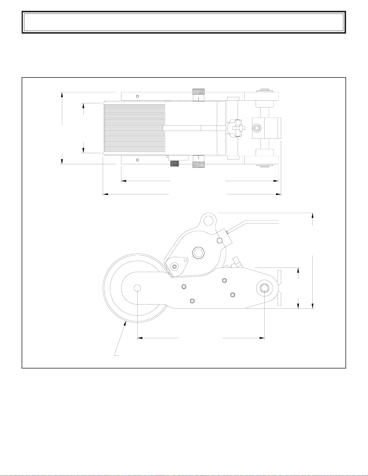
SPECIFICATIONS
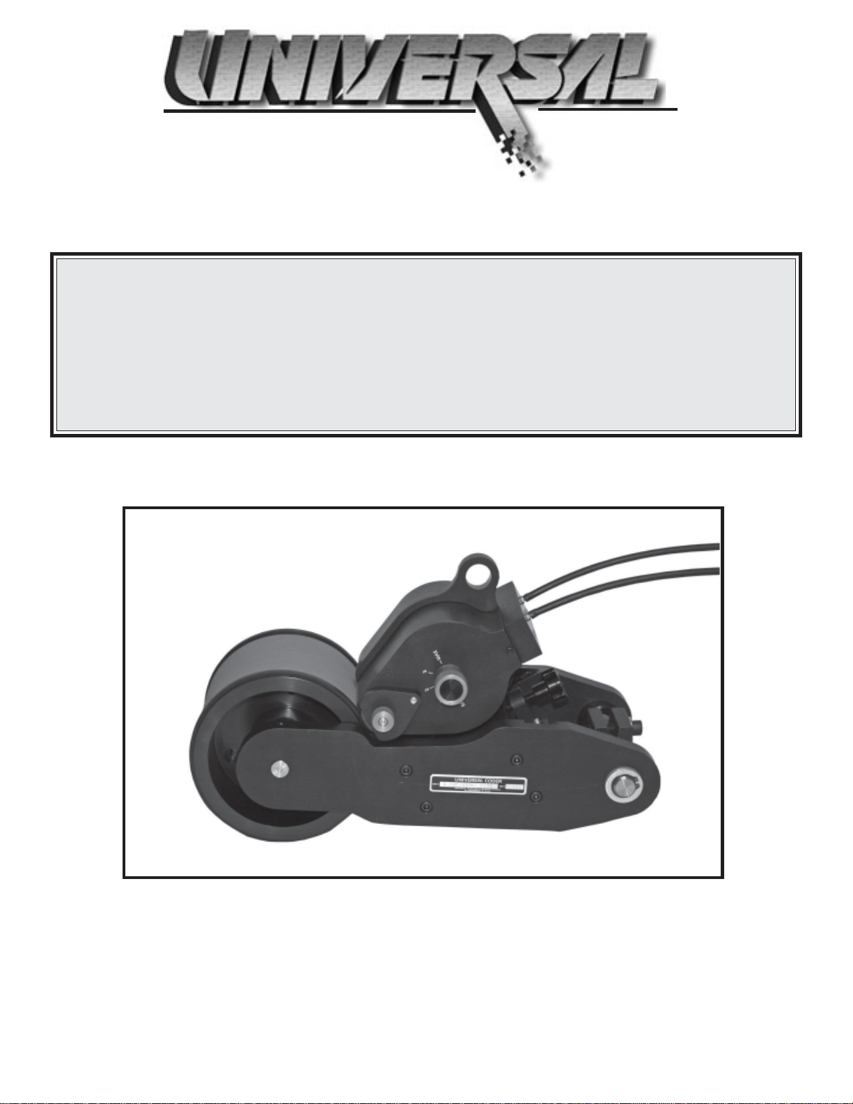
WPNP-400NI-PIDS&WPNP-400NI-T-PIDS
WPNP-400NI-PIDS-D & WPNP-400NI-T-PIDS-D
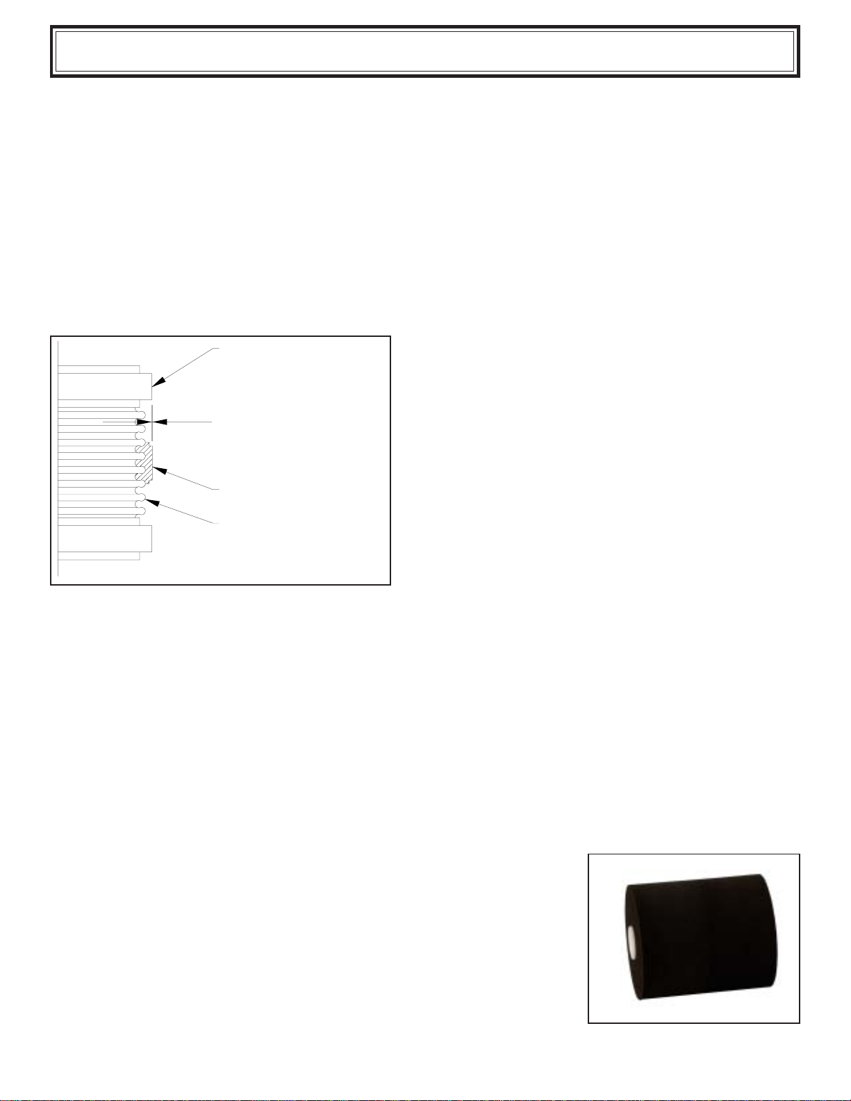
Printing Dies
XFNeopreneInkRolls
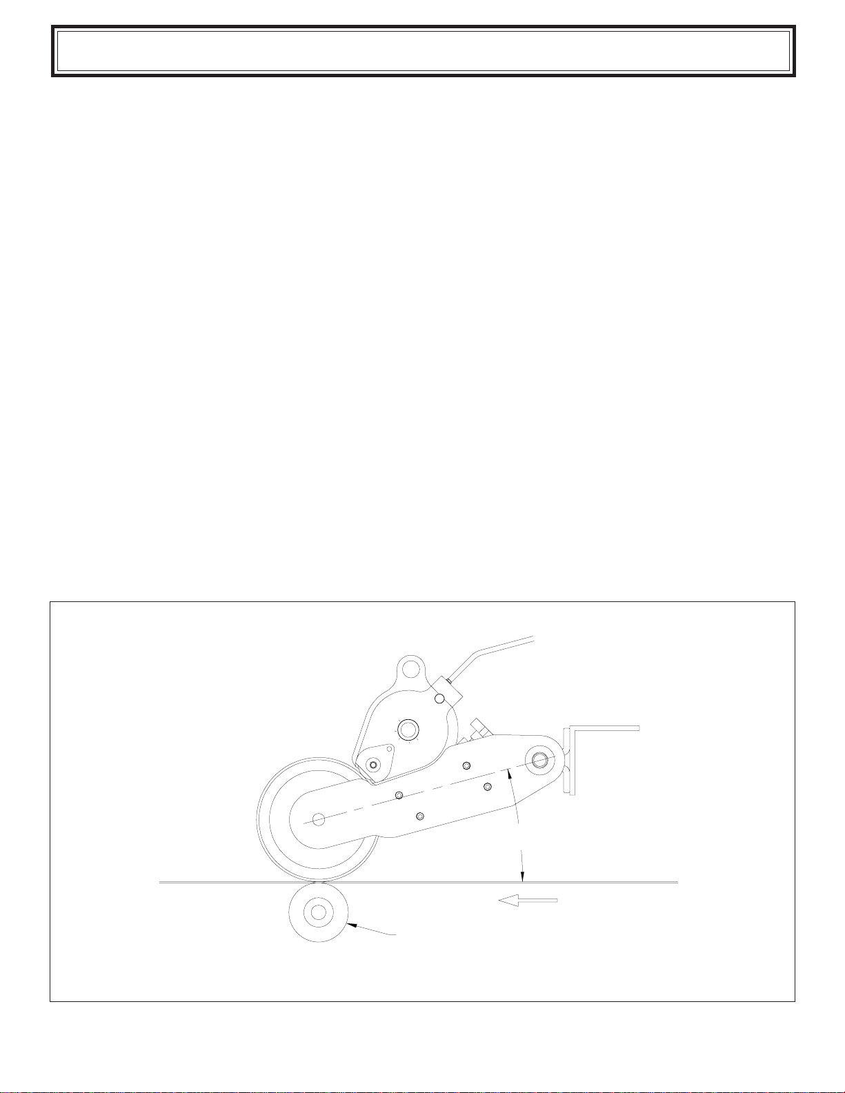
QUICK START
InstallingthePrinter
Preparing the Printer for installation of the Ink Roll
Preparing the Ink Roll for installation
InstallingtheInkRoll
Reinstalling the Inking System on the Printer
Installing the Printing Dies
Inking System PositionAdjusting Knobs
Pre-InkingtheXFNeopreneInk Roll
BASIC PRINCIPLES OF OPERATION
The Pids System
Pids-Digital-CE Programmable Ink Delivery Systems
WPNP Web Printer Interval Timer Setting
Endcoder Sensory Assembly
Installation orAdjustment of the Inductive Proximity Sensor
MAINTENANCE
Cleaning the Printer
Cleaning the Transfer Roll
Cleaning the Printing Dies
PARTS DIAGRAMS & PARTS LISTS
3
4
4
5
5
6
7
9
10
12
13
13
14
15
15
15
16
16
18
18
19
20
○○○○○○○○○○○○○○○○○○○○○○○○○○○○○○○○○○○○○○○○○○○○○○○○○○○○○○○○
○○○○○○○○○○○○○○○○○○○○○○○○○○○○○○○○○○○○○○○○○
○○○○○○○○○○○○○○○○○○○○○○○○○○○○○○○○○○○○○○○○○○○○○○○○○○○
○○○○○○○○○○○○○○○○○○○○○○○○○○○○○○○○○○○○○○○○○○○○○
○○○○○○○○○○○○○○○○○○○○○○○○○○○○○○○○○○○○○○○○○○○○○○○
○○○○○○○○○○○○○○○○○○○○○○○○○○○○○
○○○○○○○○○○○○○○○○○○○○○○○○○○○○○○○○○○○○○
○○○○○○○○○○○○○○○○○○○○○○○○○○○○○○○○○○○○○○○○○○○○○○
○○○○○○○○○○○○○○○○○○○○○○○○○○○○○○○○
○○○○○○○○○○○○○○○○○○○○○○○○○○○○○○○○○○○○○○○○○○○
○○○○○○○○○○○○○○○○○○○○○○○○○○○○○○○○○○○
○○○○○○○○○○○○○○○○○○○○○○○○○○○○○○○○○○○○○
○○○○○○○○○○○○○○○○○○○○○○○○○○○○○○○○○○○○○○○○○○○○○○○
○○○○○○○○○○○○○○○○○○○○○○○○○○○○○○○○○○○○○○○○○○
○○○○○○○○○○○○○○○○○○○○○○○○○○○○○○○○○○○○○○○○○○○
○○○○○○○○○○○○○○○○○○○○○○○○○○○○○○○○○○○○○○○○
○○○○○○○○○○○○○○○○○○○○○○○○○○○○○○○○○○○○○○○○○○○○○○○○
○○○○○○○○○○○○○○○○○○○○○○○○○○○○○○○○○
○○○○○○○○○○○○○○○○○○○○○○○
○○○○○○○○○○○○○○○○○○○○○○○○○○
○○○○○○○○○○○○○○○○○○○○○○○○○○○○○○○○
○○○○○○○○○○○○○○○○○○○○○○○○○○○○○