5
© UPLIFT Desk • 800-349-3839 • info@upliftdesk.com • upliftdesk.com
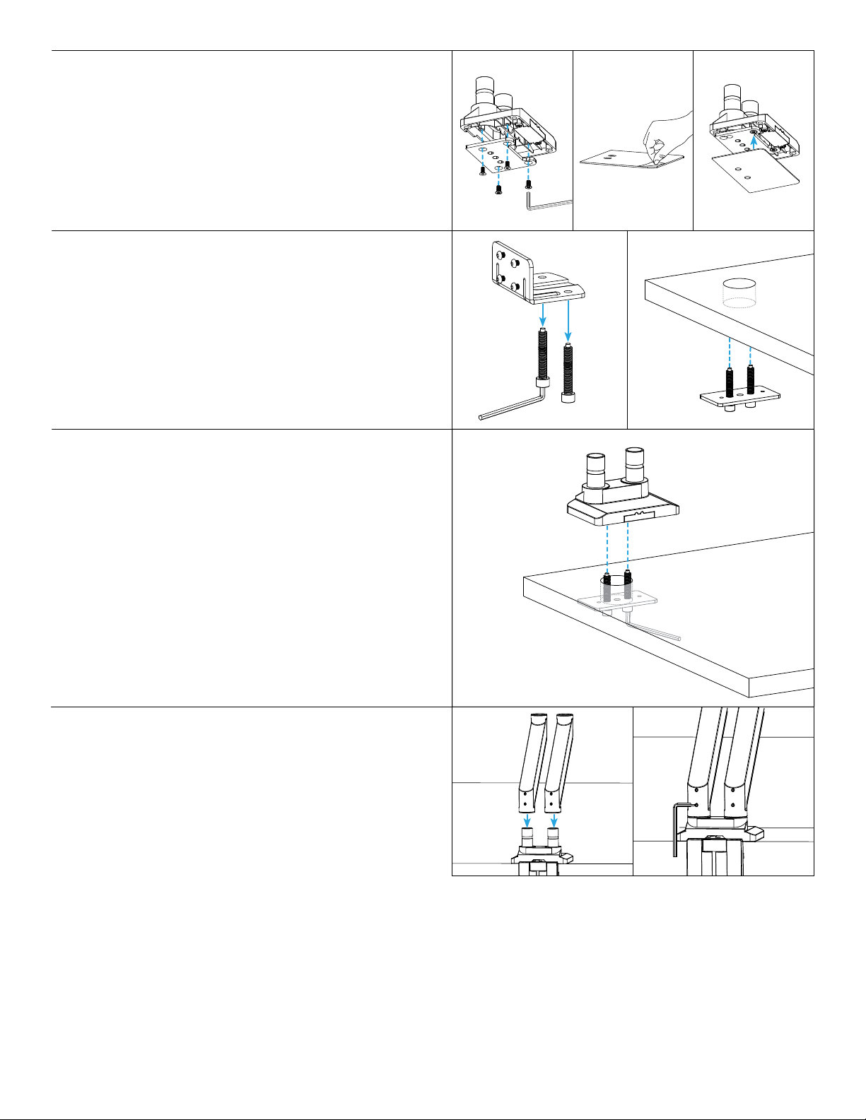
Step 9 (Bolt-Through Method)
A. While holding the Lower Base Plate and bolts in place
from below, line up the holes of the Base assembly
(from Step 7) with the top of the bolt.
B. Make sure the front of the Base assembly is facing
towards the front of your desk.
C. Hold the Base assembly in place on top as you hand
tighten each bolt, alternating from one bolt to the
other, allowing the Lower Base Plate to rise evenly. Once
each bolt is started, you can let go of the Lower Base
Plate. Use the 6mm Allen Wrench to nish tightening
the assembly to the desktop.
D. Proceed with the Arm Assembly, Step 10.
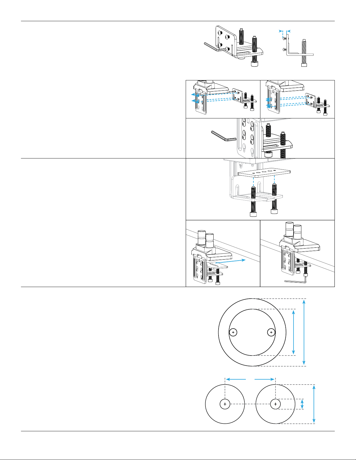
Step 7 (Bolt-Through Method)
A. Align the Upper Base Plate with the Base in the
orientation shown and attach it using the four M6 x 12
Flathead Screws and the 4mm Allen Wrench.
B. Peel the adhesive backing off of the Adhesive Pad and
attach it to the bottom of the Base and Upper Base
Plate as shown. Align the pad with the front edge of the
Base rst, then work to the back.
Step 8 (Bolt-Through Method)
A. Remove both bolts from the bottom of the Lower
Clamp using the 6mm Allen Wrench. Slip them
through the two holes on either side of the Lower Base
Plate’s center hole as shown.
B. If assembling on an adjustable height desk, raise the
desk so the desktop hole is easier to see. Then insert
the bolts through the desktop hole from below, and
hold them in place.
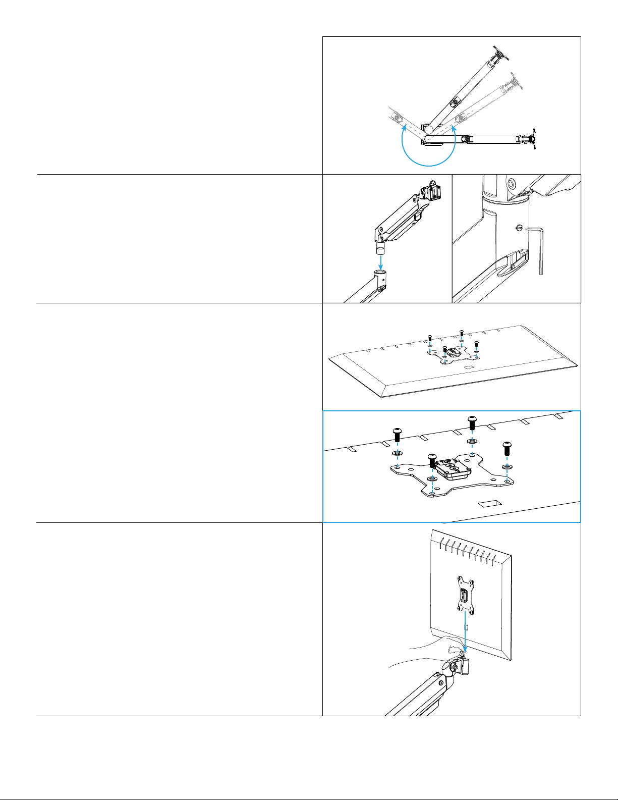
Step 10
A. Slide the Lower Arms onto the posts of the Base until
they are fully seated and tighten each lower set screw
with the at-head end of the 3mm Allen Wrench (or
a small at head screwdriver). This will secure the
Lower Arms to the Base and keep them from becoming
separated during adjustment.