iiii
Table of Contents (continued)
Section 7: Thermostat Operation .................25
Thermostat T-75 Display . . . . . . . . . . . . . . . . . . . . . . . 25
Changing the Temperature Format . . . . . . . . . . . . . . . . . . . 25
Changing the Temperature Setpoint . . . . . . . . . . . . . . . . . . 25
Setting the Minimum and Maximum Temperatures. . . . . . . . . . . . . 26
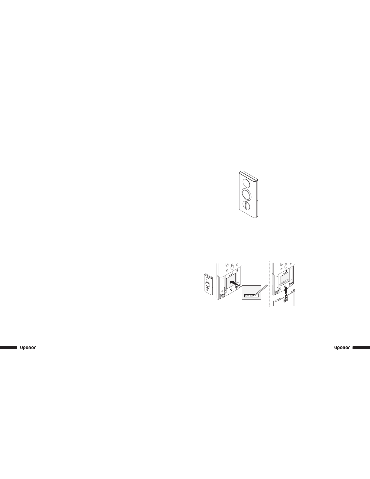
Thermostat Battery Replacement . . . . . . . . . . . . . . . . . . . 26
Section 8: Interface Operation ...................27
Interface Screens. . . . . . . . . . . . . . . . . . . . . . . . . . 28
Access Level . . . . . . . . . . . . . . . . . . . . . . . . . . . 28
Information Menu . . . . . . . . . . . . . . . . . . . . . . . . . 29
Room Temperature . . . . . . . . . . . . . . . . . . . . . . . . . 29
ECO (Economy) . . . . . . . . . . . . . . . . . . . . . . . . . . 29
Battery and Communication Status. . . . . . . . . . . . . . . . . . . 29
Thermostat and Actuator Status . . . . . . . . . . . . . . . . . . . . 29
Actuator Status . . . . . . . . . . . . . . . . . . . . . . . . . . 29
Settings menu. . . . . . . . . . . . . . . . . . . . . . . . . . . 30
Information Menu: System Information . . . . . . . . . . . . . . . . . 30
ECO Mode . . . . . . . . . . . . . . . . . . . . . . . . . . . . 30
Steps to Follow . . . . . . . . . . . . . . . . . . . . . . . . . . 30
Heating . . . . . . . . . . . . . . . . . . . . . . . . . . . . . 30
Editing the ECO Proles . . . . . . . . . . . . . . . . . . . . . . . 31
Apply ECO Prole . . . . . . . . . . . . . . . . . . . . . . . . . 31
Setting Time and Date . . . . . . . . . . . . . . . . . . . . . . . 31
Exercise Actuators and Pumps . . . . . . . . . . . . . . . . . . . . 32
Temperature Unit . . . . . . . . . . . . . . . . . . . . . . . . . 32
Backlight. . . . . . . . . . . . . . . . . . . . . . . . . . . . . 32
Installer Level . . . . . . . . . . . . . . . . . . . . . . . . . . . 32
Vacation Mode . . . . . . . . . . . . . . . . . . . . . . . . . . 32
Section 9: Technical Data . . . . . . . . . . . . . . . . . . . . . . . 33
Base Unit Connection Diagrams . . . . . . . . . . . . . . . . . . . . 34
Section 10: System Maintenance .................37
Section 11: Troubleshooting .....................39
Normal System Operating Conditions . . . . . . . . . . . . . . . . . . 39
Identifying and Resolving Alarms and Errors . . . . . . . . . . . . . . . 39
Contacting an Installer . . . . . . . . . . . . . . . . . . . . . . . 40
Contacting Uponor . . . . . . . . . . . . . . . . . . . . . . . . . 40
Troubleshooting Solutions . . . . . . . . . . . . . . . . . . . . . . 41
Section 12: Installation Report . . . . . . . . . . . . . . . . . . 47
Section 1
General
Recommendations
Safety Measures
• Read and follow the instructions in this guide.
• Installation must be performed by a qualied person
according to local code.
• It is prohibited to make changes or modications not
specied in this guide.
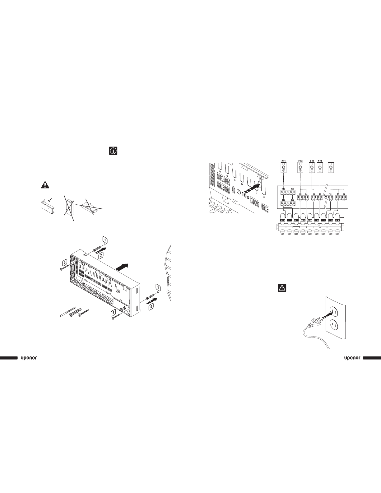
• Power must be switched off when wiring.
• Uponor is not responsible for damages and
breakdowns that may result from not following the
instructions in this guide.
Symbols Used in This Manual
Warning: Risk of bodily injuries.
Nonobservance may harm health or cause
damage to product components.
Caution: Important note on functionality
Information: Important operating advice
and information
See another document.
Press button
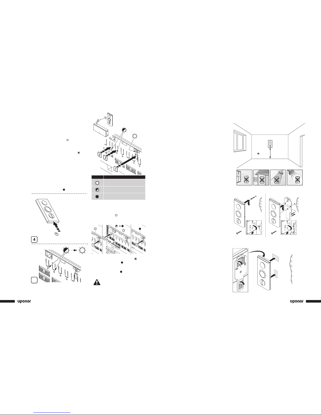
LED off
LED on
LED blinks
LED ickers
Power Supply
• The Uponor Climate Co˘ntrol™ Zoning System
uses a 110VAC/60Hz power supply.
• In case of emergency, immediately disconnect
the plug from the power.
• Do not use water to clean the Zoning System.
• Switch off power when wiring.
• Do not expose the Zoning System to ammable
vapors or gases.
Limitations for Radio Waves
The Zoning System uses radio waves. The frequency
used is reserved for similar applications, and the
chances of interference from other radio sources is
very low. However, in some rare special cases, it may
not be possible to establish a perfect communication.
The transmission range is sufcient for most
applications, but each building has different
obstacles affecting communication and maximum
transmission distance. If communication trouble exists,
Uponor can support the system with accessories, such
as repeaters, for solving the exceptional issues.
Technical Constraints
• Keep installation and data cables away from power
cables greater than 50VAC to avoid interference.
• The electrical circuits of the boiler and the pump
must be protected by a maximum 10A circuit breaker.