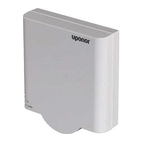
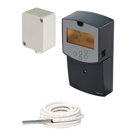
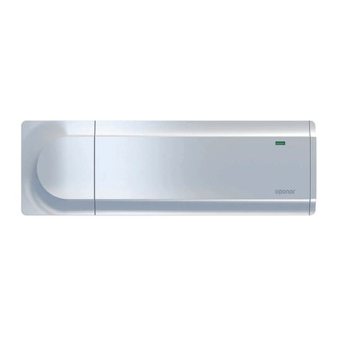
Uponor C-46 User manual

11 | 2010
INDOOR CLIMATE
CLIMATE CONTROLLER C-46
Installation and operation manual

CLIMATE CONTROLLER C-46 - INSTALLATION AND OPERATION MANUAL
2
Contents
1 Copyright and Disclaimer ............................ 4
2 Preface ........................................................... 5
2.1 Safety instructions ........................................... 5
2.2 Limitations for radio transmission .................... 5
2.3 Disposal ........................................................... 5
3 Climate Controller C-46 overview .............. 6
3.1 Description ...................................................... 6
3.1.1 Heating and cooling system example............... 6
3.1.2 Meltaway example ........................................... 7
3.2 Sensor handling ............................................... 7
3.2.1 Wired sensors................................................... 7
3.2.2 Radio thermostats............................................ 7
3.2.3 Radio thermostats through Controller C-56
Radio ............................................................... 7
3.2.4 Considerations in Heating and cooling mode... 7
3.2.5 Sensor priorities ............................................... 8
3.3 Operating modes ............................................. 8
3.3.1 Heating modes ................................................ 8
3.3.2 Cooling modes ................................................. 9
3.3.3 Meltaway mode ............................................... 9
3.3.4 Operating modes and sensor use ..................... 10
3.3.5 Heating and cooling ........................................ 10
4 System integration of Climate Controller
C-46 and Controller C-56 Radio ................. 12
5 Installing Climate Controller C-46.............. 13
5.1 Preparing the installation................................. 13
5.2 Opening the Climate Controller C-46............... 13
5.3 Wall-mounting the Climate Controller C-46..... 13
5.4 Connecting the Climate Controller C-46 .......... 14
6 Setting Up the Climate Controller C-46 .... 15
6.1 Operation interface.......................................... 15
6.1.1 Navigation keys ............................................... 15
6.1.2 Alarm indicator ................................................ 15
6.1.3 Reset button.................................................... 15
6.1.4 Data stick connector........................................ 15
6.1.5 Display............................................................. 15
6.2 Installation wizard............................................ 16
6.2.1 Language......................................................... 16
6.2.2 Set time and date ............................................ 16
6.2.3 Operating mode............................................... 16
6.2.4 Heating............................................................ 16
6.2.5 Cooling ............................................................ 17
6.2.6 Meltaway ......................................................... 17
6.2.7 H/C switchover................................................ 18
6.2.8 Switch mode .................................................... 18
6.2.9 Mixing valve mode ........................................... 18
6.3 Restarting the installation wizard ..................... 18
6.4 Operation ......................................................... 18
7 Quick menu .................................................... 19
7.1 Uponor............................................................. 19
7.2 Information screens.......................................... 19
7.2.1 Navigating information screens........................ 19
7.2.2 Date and time .................................................. 19
7.2.3 Average temperature........................................ 19
7.2.4 Return temperature.......................................... 19
7.2.5 Supply temperature.......................................... 19
7.2.6 Outdoor temperature ....................................... 19
7.2.7 Indoor temperature .......................................... 19
7.2.8 Relative humidity ............................................. 19
7.3 Parameter screens ............................................ 20
7.3.1 Navigating parameter screens .......................... 20
7.3.2 System standby mode ...................................... 20
7.3.3 Heating supply setpoint ................................... 20
7.3.4 Indoor setpoint ................................................ 20
7.3.5 T-slope............................................................. 20
7.3.6 T-adjustment ................................................... 20
7.3.7 Supply information........................................... 20
7.3.8 Cooling supply setpoint.................................... 20
7.3.9 Cooling indoor setpoint.................................... 20
7.3.10 Dew point margin............................................. 21
7.3.11 Dew point offset .............................................. 21
7.3.12 Calculated dew point........................................ 21
7.3.13 Idle setpoint ..................................................... 21
7.3.14 Melting supply setpoint ................................... 21
8 Operating the Climate Controller C-46...... 22
8.1 Main menu ....................................................... 22
8.2 Climate controller (menu) ................................ 22
8.2.1 Operating mode ............................................... 22
8.2.2 Supply temperature.......................................... 22
8.2.3 Return temperature.......................................... 22
8.2.4 Average temperature........................................ 23
8.2.5 Outdoor temperature ....................................... 23
8.2.6 Indoor temperature .......................................... 23
8.2.7 Relative humidity ............................................. 23
8.3 Zones ............................................................... 23
8.4 Control settings................................................ 23
8.4.1 Standby mode .................................................. 24
8.5 Heating ............................................................ 24

CLIMATE CONTROLLER C-46 - INSTALLATION AND OPERATION MANUAL 3
8.5.1 Supply setpoint ................................................ 24
8.5.2 Indoor setpoint ................................................ 24
8.5.3 Average setpoint .............................................. 25
8.5.4 Min./Max. supply............................................. 25
8.5.5 T-slope............................................................. 25
8.5.6 T-adjustment ................................................... 25
8.5.7 Supply information........................................... 26
8.5.8 Indoor sensor influence.................................... 26
8.5.9 Indoor sensor mode ......................................... 26
8.5.10 Heating activation............................................ 26
8.6 Cooling............................................................. 27
8.6.1 Supply setpoint ................................................ 27
8.6.2 Indoor setpoint ................................................ 27
8.6.3 Min./Max. supply............................................. 28
8.6.4 Indoor sensor influence.................................... 28
8.6.5 Dew point ........................................................ 28
8.6.6 Cooling activation ............................................ 29
8.6.7 Dehumidifier control ........................................ 29
8.7 H/C switchover ................................................ 30
8.7.1 Bus master and No bus modes ......................... 30
8.7.2 Outdoor-indoor/supply temp. ......................... 30
8.7.3 Supply water temp. .......................................... 31
8.8 Meltaway ......................................................... 31
8.9 Advanced control ............................................. 31
8.9.1 Operating mode (select) .................................. 31
8.9.2 Control response .............................................. 32
8.9.3 Filtering temp. constant ................................... 32
8.9.4 Frost protection ............................................... 32
8.9.5 Mixing valve..................................................... 33
8.9.6 Mixing valve manual operation ........................ 33
8.9.7 Pump manual operation ................................... 33
8.9.8 Valve and pump exercise.................................. 33
8.9.9 Pump management .......................................... 34
8.10 ECO mode........................................................ 34
8.10.1 Heating ............................................................ 34
8.10.2 Cooling............................................................. 36
8.11 Alarms .............................................................. 37
8.11.1 All alarms ......................................................... 37
8.11.2 Battery alarms .................................................. 37
8.12 General settings ............................................... 37
8.12.1 Access level...................................................... 38
8.12.2 Clock settings................................................... 38
8.12.3 Language ......................................................... 39
8.12.4 Temperature unit ............................................. 39
8.12.5 Backlight.......................................................... 39
8.12.6 Log mode......................................................... 39
8.12.7 General purpose output................................... 39
8.12.8 GPO status ...................................................... 40
8.12.9 Controller ID .................................................... 40
8.12.10 Software version .............................................. 40
8.13 Radio links ....................................................... 40
8.13.1 View links ........................................................ 41
8.13.2 Add links ......................................................... 41
8.13.3 Reset all links................................................... 41
8.13.4 Test radio range............................................... 41
9Menustructure............................................. 42
10 Hints and examples ...................................... 44
10.1 Economy and comfort modes .......................... 44
10.1.1 Eco off mode................................................... 44
10.1.2 Eco all mode .................................................... 44
10.1.3 Eco night mode ............................................... 45
10.1.4 Eco night and day mode.................................. 45
10.1.5 Operation example with economy mode.......... 45
10.2 Adjusting the heat curve ................................. 46
10.2.1 Description ...................................................... 46
10.2.2 Operation example .......................................... 46
10.3 Heating summer shut-off and cooling winter
shut-off ........................................................... 47
10.3.1 Heating mode without summer shut-off ......... 47
10.3.2 Heating mode with summer shut-off............... 47
10.3.3 Cooling mode without winter-shut-off............ 48
10.3.4 Cooling mode with winter-shut-off ................. 48
10.3.5 Heating and cooling mode without season shut-
offs.................................................................. 49
10.3.6 Heating and cooling mode with season shut-
offs.................................................................. 49
11 Trouble shooting .......................................... 51
12 Technical data............................................... 53

CLIMATE CONTROLLER C-46 - INSTALLATION AND OPERATION MANUAL 4
1 Copyright and Disclaimer
Uponor has prepared this Uponor Control System Installation and
Operation Manual and all the content included solely for
information purposes. The contents of the Manual (including
graphics, logos, icons, text, and images) are copyrighted and
protected by worldwide copyright laws and treaty provisions. You
agree to comply with all copyright laws worldwide in your use of
the Manual. Modification or use of any of the contents of the
Manual for any other purpose is a violation of Uponor's
copyright, trademark and other proprietary rights.
The presumption for the Manual is that the safety measures have
been fully complied with and, further, that the Uponor Control
System, including any components that are part of such system,
covered by the Manual:
•is selected, planned and installed and put into operation by a
licensed and competent planner and installer in compliance
with current (at the time of installation) installation
instructions provided by Uponor as well as in compliance with
all applicable building and plumbing codes and other
requirements and guidelines;
•has not been (temporarily or continuously) exposed to
temperatures, pressure and/or voltages that exceed the
limits printed on the products or stated in any instructions
supplied by Uponor;
•remain in its originally installed location and is not repaired,
replaced or interfered with, without prior written consent of
Uponor;
•is connected to potable water supplies or compatible
plumbing, heating and/or cooling products approved or
specified by Uponor;
•is not connected to or used with non-Uponor products, parts
or components except for those approved or specified by
Uponor; and
•does not show evidence of tampering, mishandling,
insufficient maintenance, improper storage, neglect or
accidental damage before installation and being put into
operation.
While Uponor has made efforts to ensure that the Manual is
accurate, Uponor does not guarantee or warrant the accuracy of
the information contained herein. Uponor reserves the right to
modify the specifications and features described herein, or
discontinue manufacture of the Uponor Control System
described at any time without prior notice or obligation. The
Manual is provided “as is” without warranties of any kind, either
expressed or implied. The information should be independently
verified before using it in any manner.
To the fullest extent permissible, Uponor disclaims all
warranties, expressed or implied, including, but not
limited to, the implied warranties of merchantability,
fitness for particular purpose and noninfringement.
This disclaimer applies to, but is not limited to, the accuracy,
reliability or correctness of the Manual.
Under no circumstances shall Uponor be liable for any
indirect, special, incidental or consequential damages or
loss that result from the use of or the inability to use the
materials or information in the Manual, or any claim
attributable to errors, omission or other inaccuracies in
the Manual, even if Uponor has been advised of the
possibility of such damages.
This disclaimer and any provisions in the Manual do not
limit any statutory rights of consumers.

CLIMATE CONTROLLER C-46 - INSTALLATION AND OPERATION MANUAL 5
2Preface
The Uponor Climate Controller installation manual describes how
to install and operate the components of the system. Example
applications and possible configurations of the system are also
included.
2.1 Safety instructions
Warnings used in this manual
The following symbols are used in the manual to indicate special
precautions when installing and operating any Uponor
equipment:
Safety measures
Conform to the following measures when installing and operating
any Uponor equipment:
•Read and follow the instructions in the installation and
operation manual.
•Installation must be performed by a competent person in
accordance with local regulations.
•It is prohibited to make changes or modifications not
specified in this manual.
•All power supply must be switched off before starting any
wiring work.
•Do not use water to clean Uponor components.
•Do not expose the Uponor components to flammable
vapours or gases.
•We cannot accept any responsibility for damage or
breakdown that can result from ignoring these instructions!
Power
Technical constraints
2.2 Limitations for radio transmission
The Uponor system uses radio transmission. The frequency used
is reserved for similar applications, and the chances of
interference from other radio sources are very low.
However, in some rare cases, it might not be possible to establish
perfect radio communication. The transmission range is sufficient
for most applications, but each building has different obstacles
affecting radio communication and maximum transmission
distance. If communication difficulties exist, Uponor can support
the system with accessories, such as repeaters, for solving
exceptional problems.
2.3 Disposal
The Uponor Control System consists of various recyclable
components. Uponor would be grateful if the components
(batteries, plastics, and electric or electronic parts) are sorted and
disposed of at a suitable recycling centre.
WARNING!
Risk of injury. Ignoring warnings can cause injury or
damage components.
CAUTION
Ignoring cautions can cause malfunctions.
WARNING!
The Uponor system uses 50 Hz, 230 V AC power. In
case of emergency, immediately disconnect the power.
CAUTION
To avoid interference, keep installation/data cables
away from power cables of more than 50 V.

CLIMATE CONTROLLER C-46 - INSTALLATION AND OPERATION MANUAL
6
3 Climate Controller C-46 overview
This section is a brief description of the Climate Controller C-46
as a system component and its operating modes.
3.1 Description
The Climate Controller C-46 is a primary controller for heating,
cooling and meltaway systems.
Examples of applications are:
•Underfloor heating and cooling systems
•Wall heating and cooling systems
•Ceiling cooling and heating systems
•Radiator heating system
•Meltaway system
Its main function is to regulate supply water temperature by
controlling a mixing valve actuator.
Other functions include:
•Circulation pump control
•Output for heating/cooling switchover relay
•Dew point control
3.1.1 Heating and cooling system example
The figure below shows how the Climate Controller C-46 can be
set up in a climate system. The figure also shows several system
components that can be connected to the Climate Controller
C-46. The system can use either wired sensors or radio
thermostats.
The figure is applicable for heating, cooling and heating/cooling
switchover systems. Some of the components are intended for
use with specific system modes as indicated in the table below.
NOTE!
Only Uponor sensors and thermostats should be used
in combination with the Climate Controller C-46.
Item Description
C-46 Climate Controller C-46
H-56 Relative Humidity Sensor H-56
(only used in cooling systems with dew point control)
T-54 Thermostat Public T-54 Radio
T-55 Thermostat T-54 Radio
T-75 Thermostat T-75 Radio
1 Radio antenna
2 Outdoor sensor
3 Indoor sensor
4 Supply sensor
5 Return sensor
6 Circulation pump
7 Mixing valve actuator
•Thermal, 24 V DC, 3 W, NC (see illustration above)
•Motorized, 0–10 V DC, externally powered
8 H/C switchover relay box
(only used in Heating/cooling switchover systems)
9 Diverting valve
(only used in Heating/cooling switchover systems)
10 Pipes to heating source
11 Pipes to cooling source

CLIMATE CONTROLLER C-46 - INSTALLATION AND OPERATION MANUAL 7
3.1.2 Meltaway example
The figure below shows how the Climate Controller C-46 can be
set up in a meltaway system. The figure also shows several system
components that can be connected to the Climate Controller
C-46.
3.2 Sensor handling
The Climate Controller C-46 can use sensors connected in
different ways:
•Wired sensors directly connected to the Climate Controller
C-46
•Radio thermostats linked through an antenna connected to
the Climate Controller C-46
•Radio thermostats linked through an antenna connected to
the Controller C-56 Radio, which in its turn is connected to
the Climate Controller C-46 with a cable
3.2.1 Wired sensors
The following Uponor wired sensors can be connected to the
Climate Controller C-46:
•Supply sensor
•Return sensor
•Indoor sensor
•Outdoor sensor
Each sensor type has a dedicated connector on the Climate
Controller C-46, see section 5.4 Connecting the Climate
Controller C-46, page 14.
3.2.2 Radio thermostats
If an antenna is connected to the Climate Controller C-46, the
following thermostats and sensors can be used:
•Relative Humidity Sensor H-56
•Thermostat Public T-54 Radio
•Thermostat T-55 Radio
•Thermostat T-75 Radio
•Floor sensor connected to a Thermostat Public T-54 Radio
•Outdoor sensor connected to a Thermostat Public T-54
Radio
•Indoor sensor connected to a Thermostat Public T-54 Radio
3.2.3 Radio thermostats through Controller C-56 Radio
If the Controller C-56 Radio is connected to the Climate
Controller C-46, then the following thermostats and sensors liked
to Controller C-56 Radio can be used:
•Relative Humidity Sensor H-56
•Thermostat Public T-54 Radio
•Thermostat T-55 Radio
•Thermostat T-75 Radio
•Outdoor sensor connected to a Thermostat Public T-54
Radio
•Indoor sensor connected to a Thermostat Public T-54 Radio
Note: A floor sensor connected to a Thermostat T-54 Radio,
which is linked to the Controller C-56 Radio, will not be visible on
the system bus and cannot be used by the Climate Controller
C-46.
3.2.4 Considerations in Heating and cooling mode
If the Climate Controller C-46 is working in Heating and cooling
mode, the following conditions apply:
•Wired sensors
Setpoints for heating and cooling are set separately in the
Climate Controller C-46.
•Radio thermostats
The setpoint in this case is adjusted in the thermostat.
The heating setpoint is defined as the setpoint set in the
thermostat.
The cooling setpoint is defined as the heating setpoint plus
1.5 °C.
•Radio thermostats through Controller C-56 Radio
NOTE!
Only Uponor sensors and should be used in
combination with the Climate Controller C-46.
Item Description
C-46 Climate Controller C-46
1 Simplified meltaway using timer and pushbutton
(alternative solution)
2 Meltaway controller with snow-and-ice sensor
(alternative solution)
3 Supply sensor
4 Return sensor
5 Circulation pump
6 Mixing valve actuator
•Thermal (see illustration above)
•Motorized, externally powered
7 Pipes to meltaway system
8 Pipes to heating source

CLIMATE CONTROLLER C-46 - INSTALLATION AND OPERATION MANUAL
8
Setpoint adjustment and definitions are the same as for the
case with radio thermostats connected to the Climate
Controller C-46, see above.
3.2.5 Sensor priorities
When sensors and thermostats are connected to the Climate
Controller C-46 in different ways, the following priorities apply:
1. Thermostats linked to the Climate Controller C-46 through an
antenna have the first priority.
2. Sensors directly connected to the Climate Controller C-46
have the second priority.
3. Thermostats linked to the Controller C-56 Radio, connected
to the Climate Controller C-46, have the third priority.
Example
A house is heated using a system set up in Heating – indoor
controlled mode. In this case, a Thermostat T-75 Radio is linked
to the Climate Controller C-46, using the antenna. As a backup,
an indoor sensor is directly connected to the Climate Controller
C-46.
Under normal conditions, the Climate Controller C-46 will use the
readings from Thermostat T-75 Radio to monitor the indoor
temperature.
However, if the batteries in the Thermostat T-75 Radio fail, it will
not be able to send any temperature readings to the Climate
Controller C-46. Then the Climate Controller C-46, will switch the
monitoring to the inhouse sensor instead.
When the used batteries in the Thermostat T-75 Radio are
replaced, the Thermostat T-75 Radio will go back to sending
temperature readings again. Then the Climate Controller C-46
senses this and the monitoring of indoor temperature is switched
back to the Thermostat T-75 Radio.
3.3 Operating modes
The following operating modes are available for the Climate
Controller C-46:
•Heating
•Cooling
•Heating and cooling
•Meltaway
The following sections give a brief description of the different
operating modes and list which sensors must be connected and
which operating parameters must be set as a minimum.
3.3.1 Heating modes
Depending on the sensors used, the following heating modes are
described in the sub-sections below:
•Heating – fixed supply
•Heating – outdoor controlled supply
•Heating – outdoor controlled supply with indoor
compensation
•Heating – indoor controlled
•Heating – outdoor controlled average
See also an overview in section 3.3.4 Operating modes and sensor
use, page 10.
Heating – fixed supply
In this operating mode, the Climate Controller C-46 maintains a
constant supply temperature.
The user must adjust the Heating supply setpoint parameter to
meet the heating need of the house.
The Climate Controller C-46 uses the following input:
•Readings from supply sensor
•Setting of Heating supply setpoint parameter, see section
7.3.3 Heating supply setpoint, page 20
Heating – outdoor controlled supply
In this operating mode, the Climate Controller C-46 adjusts the
supply temperature depending on the outdoor temperature. That
is to say, the supply temperature increases with falling outdoor
temperature and the other way around.
When the parameters are correctly set, the indoor temperature is
kept at a constant level. See also section 10.2 Adjusting the heat
curve, page 46.
The Climate Controller C-46 works with the following input:
•Readings from supply sensor
•Readings from outdoor sensor
•Readings from floor sensor (optional)
•Setting of T-slope parameter, see section 7.3.5 T-slope,
page 20
•Setting of T-adjustment parameter, see section 7.3.6 T-
adjustment, page 20
•Setting of Min./Max. supply parameter, see section 6.2.4
Heating, page 16
Heating – outdoor controlled supply with indoor
compensation
In this operating mode, the Climate Controller C-46 adjusts the
supply temperature depending on both the outdoor and indoor
temperatures. That is to say, the supply temperature increases
with falling outdoor temperature and the other way around.
When the parameters are correctly set, the indoor temperature
will be kept at a constant level. See also section 10.2 Adjusting
the heat curve, page 46.
The supply temperature is adjusted as the Climate Controller
C-46 compares the readings from the indoor sensor against the
indoor setpoint temperature. A deviation of 1 °C in indoor
temperature results in a 4 °C compensation of the supply
temperature (default setting).
The Climate Controller C-46 works with the following input:
•Readings from supply sensor
•Readings from outdoor sensor
•Readings from indoor sensor
•Setting of Indoor setpoint parameter, see section 7.3.4
Indoor setpoint, page 20
•Setting of T-slope parameter, see section 7.3.5 T-slope,
page 20
•Setting of T-adjustment parameter, see section 7.3.6 T-
adjustment, page 20

CLIMATE CONTROLLER C-46 - INSTALLATION AND OPERATION MANUAL 9
•Setting of Min./Max. supply parameter, see section 6.2.4
Heating, page 16
•Setting of Indoor sensor influence parameter, see section
8.5.8 Indoor sensor influence, page 26
Heating – outdoor controlled average
In this operating mode, the Climate Controller C-46 adjusts the
supply temperature depending on the average supply–return
temperature.
When the parameters are set, the indoor temperature will be kept
at a constant level. See also section 10.2 Adjusting the heat
curve, page 46.
The supply temperature is adjusted as the Climate Controller
C-46 compares the mean value of the readings from the return
and supply sensors against the average setpoint temperature.
The Climate Controller C-46 works with the following input:
•Readings from supply sensor
•Readings from outdoor sensor
•Readings from return sensor
•Setting of Average setpoint parameter, see section 8.5.3
Average setpoint, page 25
•Setting of T-slope parameter, see section 7.3.5 T-slope,
page 20
•Setting of T-adjustment parameter, see section 7.3.6 T-
adjustment, page 20
•Setting of Min./Max. supply parameter, see section 8.5.4
Min./Max. supply, page 25
Heating – indoor controlled
In this operating mode, the Climate Controller C-46 adjusts the
supply temperature to make the indoor temperature meet the
indoor setpoint.
The Climate Controller C-46 works with the following input:
•Readings from supply sensor
•Readings from indoor sensor
•Setting of Indoor setpoint parameter, see section 7.3.4
Indoor setpoint, page 20
•Setting of Min./Max. supply parameters, see section 8.5.4
Min./Max. supply, page 25
3.3.2 Cooling modes
Depending on the sensors used, the following cooling modes are
available:
•Cooling – fixed supply
•Cooling – indoor compensated supply with dew point control
See also an overview in section 3.3.4 Operating modes and sensor
use, page 10.
Cooling – fixed supply
In this operating mode, the Climate Controller C-46 maintains a
constant supply temperature.
The user must adjust the Cooling supply setpoint parameter to
meet the cooling need of the house.
The Climate Controller C-46 works with the following input:
•Readings from supply sensor
•Readings from floor sensor (optional)
•Setting of Indoor setpoint parameter, see section 8.6.2
Indoor setpoint, page 27
•Setting of Min./Max. supply parameters, see section 8.6.3
Min./Max. supply, page 28
Cooling – indoor controlled
In this operating mode, the Climate Controller C-46 adjusts the
supply temperature to make the indoor temperature meet the
indoor setpoint.
The user must adjust the Cooling supply setpoint parameter to
meet the cooling need of the house.
The Climate Controller C-46 works with the following input:
•Readings from supply sensor
•Readings from indoor sensor
•Readings from floor sensor (optional)
•Setting of Cooling supply setpoint parameter, see section
7.3.8 Cooling supply setpoint, page 20
Cooling – indoor compensated supply with dew point
control
In this operating mode, the Climate Controller C-46 adjusts the
supply temperature depending on the calculated dew point to
prevent condensation.
The Climate Controller C-46 works with the following input:
•Readings from supply sensor
•Readings from indoor sensor
•Readings from Humidity sensor H-56
•Setting of Cooling supply setpoint parameter, see section
7.3.8 Cooling supply setpoint, page 20
•Setting of Indoor setpoint parameter, see section 8.5.2
Indoor setpoint, page 24
•Setting of Indoor sensor influence parameter, see section
8.5.8 Indoor sensor influence, page 26
•Setting of Dew point margin parameter, see section 8.6.7
Dehumidifier control, page 29
•Setting of Dew point offset parameter, see section 8.6.7
Dehumidifier control, page 29
3.3.3 Meltaway mode
In this operating mode, the Climate Controller C-46 maintains a
constant supply temperature to either meet the Idle setpoint
temperature or the Melting supply setpoint temperature.
A separate snow and ice meltaway product with a snow sensor
can also be connected to the Climate Controller C-46.
The Climate Controller C-46 works with the following input:
•Readings from supply sensor
•Readings from return sensor
•Setting of Idle setpoint parameter, see section 7.3.13 Idle
setpoint, page 21
•Setting of Melting supply setpoint parameter, see section
7.3.14 Melting supply setpoint, page 21

CLIMATE CONTROLLER C-46 - INSTALLATION AND OPERATION MANUAL
10
3.3.4 Operating modes and sensor use
The table below shows which sensors are used in which operating
mode.
3.3.5 Heating and cooling
H/C switchover – indoor-outdoor temperature controlled
In this switchover mode, the Climate Controller C-46 switches
between heating and cooling mode depending on the
temperature readings from the indoor and outdoor sensors. The
Climate Controller C-46 can also control an external diverting
valve through a relay contact.
This switchover mode requires that either the Bus master or No
bus function is selected from the H/C switchover menu. See
section 8.7 H/C switchover, page 30. The bus settings refer to
the Uponor Control Systems internal bus.
Both an indoor sensor and an outdoor sensor must be connected
to the Climate Controller C-46 for the switchover function. The
same sensors are also used for the heating and cooling functions
if required.
It is possible to select any of the available heating modes for the
heating function and any of the available cooling functions for
the cooling mode. See sections above.
The Climate Controller C-46 works with the following input for
the H/C switchover function:
•Readings from indoor sensor
•Readings from outdoor sensor
•Setting of Outdoor trigger temp. parameter, see section
8.7.2 Outdoor-indoor/supply temp., page 30
•Setting of Outdoor trigger delay parameter, see section
8.7.2 Outdoor-indoor/supply temp., page 30
•Setting of Indoor trigger temp. parameter, see section
8.7.2 Outdoor-indoor/supply temp., page 30
•Setting of Indoor trigger delay parameter, see section
8.7.2 Outdoor-indoor/supply temp., page 30
H/C switchover – supply temperature controlled
In this switchover mode, the Climate Controller C-46 switches
between heating and cooling mode depending on the primary
supply water temperature.
If the water supplied is below a defined trigger value, the Climate
Controller C-46 switches over to cooling mode. If the water
supplied is above the same trigger value and a defined hysteresis
value, the Climate Controller C-46 switches over to heating mode.
A hysteresis parameter is defined to achieve correct switchover
operations.
This switchover mode requires that either the Bus master or No
bus function is selected from the H/C switchover menu. See
section 8.7 H/C switchover, page 30. The bus settings refer to
the Uponor Control Systems internal bus.
It is possible to select any of the available heating modes for the
heating function and any of the available cooling modes for the
cooling function. See sections above.
The Climate Controller C-46 works with the following input for
the H/C switchover function:
•Readings from supply sensor
•Setting of Supply temperature parameter, see section
8.7.3 Supply water temp., page 31
•Setting of Hysteresis parameter, see section 8.7.3 Supply
water temp., page 31
H/C switchover manual mode
In this switchover mode, the Climate Controller C-46 switches
between heating and cooling when the user manually sets it to
either mode.
The Climate Controller C-46 enters heating mode when the user
selects Heating in the H/C switchover menu. See section 8.7
H/C switchover, page 30.
The Climate Controller C-46 enters cooling mode when the user
selects Cooling in the H/C switchover menu. See section 8.7
H/C switchover, page 30.
Operating mode Supply
sensor
Outdoor
sensor
Indoor
sensor
Return
sensor
Relative
humidity
sensor
Floor
sensor
Heating – fixed supply X
Heating – outdoor controlled supply X X O
Heating – outdoor controlled supply with indoor compensation X X X
Heating – outdoor controlled average X X X
Heating – indoor controlled X X
Cooling – fixed supply X O
Cooling – indoor controlled X X O
Cooling – indoor compensated supply with dew point control X X X X O
Meltaway X X
X = the sensor must be used in this operating mode
O = the sensor is optional

CLIMATE CONTROLLER C-46 - INSTALLATION AND OPERATION MANUAL 11
It is possible to select any of the available heating modes for the
heating function and any of the available cooling modes for the
cooling function. See sections above.
H/C switchover in slave mode
In this switchover mode, the Climate Controller C-46 switches
between heating and cooling mode controlled from an external
source.
There are two ways to set the Climate Controller C-46 in slave
mode:
•If the Bus slave function is selected from the H/C
switchover menu, the switchover function will be controlled
from a Controller C-56 Radio.
•If the General purpose input function is selected in either
the Bus master menu or the No bus menu, the switchover
function will be controlled from an external source. See
section 8.7.1 Bus master and No bus modes, page 30.
An external source can for example be a manual switch or a
heat pump.

CLIMATE CONTROLLER C-46 - INSTALLATION AND OPERATION MANUAL
12
4 System integration of Climate Controller C-46 and
Controller C-56 Radio
The Climate Controller C-46 can be integrated with the Controller
C-56 Radio to enhance the capabilities of the climate system.
Controllers C-56 Radio with assembly date 4010 or later have the
correct software version. Date format is WWYY. A sticker with the
assembly date can be found on the high voltage compartment
when the cover is removed.
Controllers C-56 Radio with an older assembly date can be
upgraded by Uponor. Please contact Uponor for more
information.
Some typical configurations with Climate Controller C-46 and
Controller C-56 Radio interconnected are listed below:
•If a circulation pump is connected to the Climate Controller
C-46, the pump management decisions can be made by
Controller C-56 Radio. This means that the pump will be
stopped when there is no heating or cooling demand.
•One or more Relative Humidity Sensors H-56 connected
through Controller C-56 Radio. This configuration can use
the average or maximum relative humidity in a zone.
•One or more extra indoor thermostats connected through
Controller C-56 Radio. This configuration can be used to
calculate the average temperature or the greatest deviation
from the setpoint temperature in a zone.
•Outdoor temperature sensor connected through Controller
C-56 Radio
•Economy and comfort modes controlled by the timer
function in Interface I-76 through Controller C-56 Radio.
•Holiday mode controlled by the timer function in Interface
I-76 through Controller C-56 Radio
•Heating/cooling switch controlled from the menu in
Interface I-76 through Controller C-56 Radio or from external
Heating/cooling switch connected to the Controller C-56
Radio
The illustration below shows an example configuration.
For instructions how to connect the Controller C-56 Radio to
Climate Controller C-46, see section 5.4 Connecting the Climate
Controller C-46, page 14.
For instructions how to connect and link components to the
Controller C-56 Radio, see Uponor Control System, Installation
and Operation Manual.
NOTE!
The Controller C-56 Radio must be equipped with
software version 5.0.3 or later to work correctly in
connection with Climate Controller C-46.
NOTE!
The Climate Controller C-46 will go to economy mode
only if all zones controlled by Controller C-56 Radio
are in economy mode.

CLIMATE CONTROLLER C-46 - INSTALLATION AND OPERATION MANUAL 13
5 Installing Climate Controller C-46
5.1 Preparing the installation
Follow the guidelines below to determine the best installation
position:
1. Study the connection diagrams of the Climate Controller
C-46, see section 5.4 Connecting the Climate Controller C-
46, page 14.
2. Ensure that AC power is available for connection of the
Climate Controller C-46.
3. Ensure that the installation position is free from running and
dripping water.
4. Ensure that there is no risk for overheating of the Climate
Controller C-46 due to high ambient temperature.
5. Select a mounting position on a vertical surface at a height
that is convenient for operation of the Climate Controller
C-46.
5.2 Opening the Climate Controller C-46
To open the Climate Controller C-46:
1. Carefully lift the cover, starting at the upper edge.
2. Loosen the captive screw which fixes the upper compartment
to the lower.
3. Lift the upper compartment to reach the signal cable
connected between the upper and lower compartments.
4. Disconnect the signal cable from the lower compartment.
5.3 Wall-mounting the Climate Controller
C-46
The Climate Controller C-46 is delivered in a kit including screws
and wall plugs. The figure below shows the Climate Controller
C-46 dimensions and the mounting hole positions.
Pos. Item
1Cover
2 Upper compartment
3 Lower compartment
4 Fixing screw
5 Interconnection signal cable
6 Fuse T 5 A/250 V and spare fuse

CLIMATE CONTROLLER C-46 - INSTALLATION AND OPERATION MANUAL
14
5.4 Connecting the Climate Controller C-46
Connections of sensors and other equipment is made in both the
lower and upper compartments.
Lower compartment
The figure below shows an example of cable connection in the
lower compartment.
* Only one of these ports can be used in the same installation
1. Connect cables to be used as indicated in the figure and table
above.
2. Loosen the cable clamp closest to each cable and route the
cable through the clamp.
3. Tighten the cable clamp firmly and ensure that the cables are
fixed.
Upper compartment
The figure below shows an example of cable connection in the
upper compartment. On top of the illustration is the cover inside
with label.
1. Connect cables to be used as indicated in the figure and table
above.
2. Loosen the cable clamp closest to each cable and route the
cable through the clamp.
3. Tighten the cable clamp firmly and ensure that the cables are
fixed.
4. Reconnect the signal cable from the upper compartment to
the lower.
5. Put back the upper compartment on top of the lower and
tighten the fixing screw.
6. Put back the cover onto the upper compartment.
Connectors Connections in lower compartment
A-B Supply temperature sensor input
C-D Return temperature sensor input
E-F * +24 V DC output for thermal actuator
G-H * 0–10 V DC output for motorized valve
I-J Pump output
K-L 230 V AC power supply
7 Earth ground
Connectors Connections in upper compartment
1-2 Active antenna connection
3-4 C-56 connection
5-6 General purpose input
7-8 Indoor temperature sensor input
9-10 Outdoor temperature sensor input
11-12 General purpose output relay

CLIMATE CONTROLLER C-46 - INSTALLATION AND OPERATION MANUAL 15
6 Setting Up the Climate Controller C-46
The Climate Controller C-46 features a four row display and a set
of navigation keys for the operation.
6.1 Operation interface
The Climate Controller C-46 operating interface is shown in the
figure below.
6.1.1 Navigation keys
Each of the five navigation keys on the front has dual functions
as described in the table below.
6.1.2 Alarm indicator
The alarm indicator flashes in case there is any alarm detected in
the Climate Controller C-46. See section 8.11.1 All alarms, page
37.
6.1.3 Reset button
Pushing the reset button resets the settings made on Language
and Time and date screens. See sections 6.2.1 Language, page
16 and 6.2.2 Set time and date, page 16.
6.1.4 Data stick connector
The data stick connector is for Uponor data stick use only.
6.1.5 Display
The display shows the basic system information in the default
state. There are three different screen modes to display further
information to the user:
•Installation wizard
This screen mode is presented when the Climate Controller
C-46 is powered up for the very first time at installation. This
screen mode is also used after changing or resetting the
operating mode. See section 6.2 Installation wizard, page 16
for more information.
•Quick menu
This screen mode is used to display a number of screens
displaying basic information for daily use. If the Climate
Controller C-46 is set to Installer access level, it is also
possible to set some basic parameters. See section 7 Quick
menu, page 19 for more information.
•Main menu
The main menu and all its sub-menus are used for displaying
any accessible information, parameter settings, and selecting
operating modes that are accessible in the system. See
section 8 Operating the Climate Controller C-46, page 22 for
more information.
Pos. Description
1 Navigation keys
2 Alarm indicator
3 Reset button
4 Data stick connector
5 Display
Key Functions
Displays next menu or Moves to next field
Displays previous menu or Moves to previous
field
Moves to line above or Increases value
Moves to line below or Decreases value
OK Displays next screen or Confirms selections;
displays current
menu
Key Functions

CLIMATE CONTROLLER C-46 - INSTALLATION AND OPERATION MANUAL
16
The following screen is displayed as default in basic access level:
6.2 Installation wizard
When the Climate Controller C-46 is started the very first time, it
will guide the operator to make the necessary primary settings of
the system.
The installation wizard is also started after changing or resetting
the operating mode.
6.2.1 Language
1. Use the and keys to
select the preferred
language.
2. Press OK to display the
next screen, see section
6.2.2 Set time and date.
6.2.2 Set time and date
1. Use the and keys to
change the highlighted
setting.
2. Use the and keys to
move to the next field.
3. Press OK to display the
next screen, see section 6.2.3 Operating mode
6.2.3 Operating mode
1. Use the and keys to
select the Operating
Mode.
Depending on the
configuration of the
Climate Controller C-46,
the following operating modes are available:
•Heating
•Heating + Cooling
•Cooling
•Meltaway
2. Press OK to display the next screen, see section 6.2.4
Heating, page 16, 6.2.5 Cooling, page 17, or 6.2.6 Meltaway,
page 17.
6.2.4 Heating
The screen Heating: Sensors Used is displayed if either
Heating or Heating + Cooling mode has been selected in the
previous screen.
The Supply sensor is selected by default and cannot be
unselected.
One to three sensors can be selected, including the default
Supply sensor.
Pos. Icon Description
1Basic access level
Installer access level
2Supply
or
Measured Supply temperature in most
Heating and all Cooling operating modes
Indoor
or
Measured Indoor temperature in Heating
– indoor controlled mode
Idle
Melting
Idle or Melting in Meltaway operating
mode
3Power-on indicator
•On = Climate Controller C-46 is
powered on
•Flashing = Climate Controller C-46 is in
standby mode
4Heating mode indicator
Cooling mode indicator
5Mixer valve
Mixer valve is opening
Mixer valve is closing
6Supply circuit pump operating
Supply circuit pump standby
Supply circuit pump not managed
7Comfort mode
Economy mode
Pos. Icon Description

CLIMATE CONTROLLER C-46 - INSTALLATION AND OPERATION MANUAL 17
1. Use the navigation keys to
highlight a sensor to be
used.
2. Press OK to select the
sensor.
3. Press OK again to clear a
selection if necessary.
4. Navigate to the OK field and press OK to display the next
screen.
5. In the screen Min./max.
supply, set the required
minimum and maximum
temperatures in the
supply circuit.
Minimum supply temperature:
•Default setting: 5 °C
•Setting range: 5–35 °C
•Setting accuracy: 1 °C
Maximum supply temperature:
•Default setting: 40 °C
•Setting range: 5–70 °C
•Setting accuracy: 1 °C
6. Press OK to confirm the settings.
7. In the screen Heating
Deact. Mode, use the
navigation keys to
highlight the heating
deactivation mode to be
used.
The following modes are available:
•Outdoor
•Always active
8. Press OK to confirm the selection.
The next screen is displayed, see section 6.2.5 Cooling, page
17, or 6.2.9 Mixing valve mode, page 18.
6.2.5 Cooling
The screen Cooling: Sensors Used is displayed if either Cooling
or Heating + Cooling mode has been selected in the previous
screen.
The Supply sensor is selected by default and cannot be cleared.
One to four sensors can be selected, including the default
Supply sensor.
1. Use the navigation keys to
highlight a sensor to be
used.
RH = relative humidity
sensor.
2. Press OK to select a
sensor.
3. Press OK again to clear a selection if necessary.
4. Navigate to the OK field and press OK to display the next
screen.
5. In the screen Min./max.
supply, set the required
minimum and maximum
temperatures in the
supply circuit.
Minimum supply temperature:
•Default setting: 8 °C
•Setting range: 5–40 °C
•Setting accuracy: 1 °C
Maximum supply temperature:
•Default setting: 25 °C
•Setting range: 5–40 °C
•Setting accuracy: 1 °C
6. Press OK to confirm the settings.
7. In the screen Cooling
Deact. Mode, use the
navigation keys to
highlight the cooling
deactivation mode to be
used.
The following modes are available:
•Outdoor
•Always active
8. Press OK to confirm the selection.
The next screen is displayed, see section 6.2.7 H/C
switchover, page 18, or 6.2.9 Mixing valve mode, page 18.
6.2.6 Meltaway
The screen Meltaway: Sensors Used is displayed if Meltaway
mode has been selected in the previous screen.
All three sensors, Supply, Return, and Meltaway are selected
by default and cannot be cleared.
1. Press OK to confirm the
default selection of all
three sensors.
2. In the screen Min./max.
supply, set the required
minimum and maximum
temperatures in the
supply circuit.
Minimum supply temperature:
•Default setting: 5 °C
•Setting range: 5–35 °C
•Setting accuracy: 1 °C
Maximum supply temperature:
•Default setting: 40 °C
•Setting range: 5–70 °C
•Setting accuracy: 1 °C
3. Press OK to confirm the settings.

CLIMATE CONTROLLER C-46 - INSTALLATION AND OPERATION MANUAL
18
The next screen is displayed, see section 6.2.9 Mixing valve
mode, page 18.
6.2.7 H/C switchover
The internal system bus is used to control the heating/cooling
swithover function when a Controller C-56 Radio is connected to
the Climate Controller C-46.
The following bus modes are selectable:
•Bus master = the Climate Controller C-46 controls the
communication on the system bus
•Bus slave = the Climate Controller C-46 works as a slave on
the bus, which is controlled by the Controller C-56 Radio
•No bus = the internal system bus is not used
1. Use the navigation keys to
highlight the system bus
to be used.
2. Press OK to display the
next screen, see section
6.2.8 Switch mode.
6.2.8 Switch mode
1. Use the navigation keys to
highlight the switched
mode to be used.
2. Press OK to display the
next screen, see section
6.2.9 Mixing valve mode.
6.2.9 Mixing valve mode
1. Use the navigation keys to
highlight the mixing valve
mode to be used.
2. Press OK to display the next screen.
The installation wizard is
complete and the Uponor
screen is displayed.
6.3 Restarting the installation wizard
If there is any kind of mistake made when using the installation
wizard, then do this to restart it:
1. Preferred method:
1.1. Press the the two keys
and
simultaneously until
the screen Access
level is displayed:
1.2. Confirm the selection by pressing OK.
Continue with step 2. below.
Alternative method:
1.1. Navigate through the screens using the navigation keys:
Uponor > Main menu > General settings >
Access level
Example screen:
1.2. Select the Installer access level and press OK.
Continue with step 2. below.
2. Navigate through the screens using the navigation keys
Uponor > Main menu > Control settings > Advanced >
Operating mode
Example screen:
3. Select the preferred operating mode using the and keys.
4. Confirm the selection by pressing OK.
5. To answer the question
Change Operating
mode, are you sure?,
select Yes and press OK.
The installation wizard is now restarted and the next screen
displays sensors to be selected. See section section 6.2.4
Heating, page 16, 6.2.5 Cooling, page 17, or 6.2.6 Meltaway,
page 17.
6.4 Operation
Starting operation
1. Press the OK button to display the Main menu screen.
The operation of the Climate Controller C-46 is described in the
Operation Manual, that is found on the CD supplied with the
equipment.

CLIMATE CONTROLLER C-46 - INSTALLATION AND OPERATION MANUAL 19
7 Quick menu
The Quick menu consists of a series of screens easily accessible
from the Uponor screen. These screens displays readings for daily
use. If the Climate Controller C-46 is set to Installer access level,
it is also possible to modify some parameters.
For a full access to all screens in the Climate Controller C-46, see
section 8 Operating the Climate Controller C-46, page 22.
7.1 Uponor
The Uponor screen is the start
screen. It is the default screen
shown when the Climate
Controller C-46 is not
accessed by the user.
For a complete description of
the information displayed on the Uponor screen, see section
6.1.5 Display, page 15.
1. Press the key to display the Date and time screen.
2. Press the key to display the first temperature information
screen.
7.2 Information screens
The information screens can be accessed when the Climate
Controller C-46 is set up in Basic access level as well as Installer
access level.
7.2.1 Navigating information screens
To navigate through the information screens:
1. Press the key to display the next information screen.
Press the key to display the previous information screen.
Example screen:
7.2.2 Date and time
The Date and time screen
can be displayed in any
Climate Controller C-46 mode.
7.2.3 Average temperature
The average temperature is
the mean value of the supply
and return temperatures. This
screen is displayed if the
Climate Controller C-46 is set
up in Heating – outdoor controlled average mode.
7.2.4 Return temperature
The return temperature is
displayed if the Climate
Controller C-46 is set up in
Heating – outdoor
controlled average mode or
Meltaway mode.
7.2.5 Supply temperature
The supply temperature is
displayed if the Climate
Controller C-46 is set up in
Heating – indoor
controlled mode or
Meltaway mode.
7.2.6 Outdoor temperature
The outdoor temperature is
displayed if the Climate
Controller C-46 is set up in
any Heating – outdoor
controlled mode.
7.2.7 Indoor temperature
The indoor temperature is
displayed if the Climate
Controller C-46 is set up in
Heating – outdoor
controlled supply with
indoor compensation mode
or Cooling – fixed supply with dew point control mode.
7.2.8 Relative humidity
The relative humidity is
displayed if the Climate
Controller C-46 is set up in
Cooling – fixed supply with
dew point control mode.
NOTE!
Depending on both the operating mode of Climate
Controller C-46 and its access level, only a selection
of the screens described below will be accessible. See
description for each screen.

CLIMATE CONTROLLER C-46 - INSTALLATION AND OPERATION MANUAL
20
7.3 Parameter screens
The parameter setting screens can only be accessed when the
Climate Controller C-46 is set up in Installer access level.
7.3.1 Navigating parameter screens
To navigate through the parameter setting screens:
1. Press OK for two seconds to highlight the parameter.
2. Press the and keys to change the parameter value.
3. Press OK to confirm the setting.
4. Press the key to display the next screen.
Press the key to display the previous information screen.
Example screens:
7.3.2 System standby mode
The System standby mode can be set in any Climate Controller
C-46 operating mode.
Standby modes:
•Normal operation
(default)
•System standby
7.3.3 Heating supply setpoint
The Heating supply setpoint can be set if the Climate
Controller C-46 is set up in Heating – fixed supply mode.
Setpoint values:
•Default setting: 35 °C
•Setpoint range: 5–40 °C
7.3.4 Indoor setpoint
The Indoor setpoint can be set if a wired indoor sensor is used
and the Climate Controller C-46 is set up in Heating – indoor
controlled mode or Heating – outdoor controlled supply
with indoor compensation mode.
Setpoint values:
•Default setting: 22 °C
•Setpoint range: 5–35 °C
7.3.5 T-slope
The T-slope parameter can be set if the Climate Controller C-46
is set up in any Heating – outdoor controlled mode.
The T-slope parameter defines the gradient of the temperature
graph. For more information, see section 10.2 Adjusting the heat
curve, page 46.
Parameter values:
•Default setting: 0.2
•Parameter range: 0.1–1.6
7.3.6 T-adjustment
The T-adjustment parameter can be set if the Climate Controller
C-46 is set up in any Heating – outdoor controlled mode.
The T-adjustment parameter defines the offset used for the
temperature graph. For more information, see section 10.2
Adjusting the heat curve, page 46.
Parameter values:
•Default setting: 3
•Parameter range: -8 to +8
7.3.7 Supply
information
The Supply information can be displayed if the Climate
Controller C-46 is set up in any Heating – outdoor controlled
mode.
The supply information is
used as a tool when tuning the
temperature graph with the
T-slope and T-adjustment
parameters. The screen
displays the supply
temperature for four different outdoor temperatures. For more
information, see section 10.2 Adjusting the heat curve, page 46.
7.3.8 Cooling supply setpoint
The Cooling supply setpoint can be set if the Climate
Controller C-46 is set up in any Cooling mode.
Setpoint values:
•Default setting: 18 °C
•Setpoint range: 5–25 °C
7.3.9 Cooling indoor
setpoint
The Cooling indoor setpoint can be set if a wired indoor sensor
is used and the Climate Controller C-46 is set up in Cooling –
indoor compensated supply with dew point control mode.
Setpoint values:
•Default setting: 20 °C
•Setpoint range: 5–35 °C
Table of contents
Other Uponor Temperature Controllers manuals

Uponor
Uponor Smatrix Base PULSE User manual

Uponor
Uponor Climate Control Zoning System User manual

Uponor
Uponor UponorControl System User manual

Uponor
Uponor SmatrixMove User manual

Uponor
Uponor SETPOINT 500 SERIES User manual

Uponor
Uponor Smatrix Move User manual

Uponor
Uponor c56 User manual

Uponor
Uponor KRS 6 User manual

Uponor
Uponor C-33 User manual
Popular Temperature Controllers manuals by other brands

Gira
Gira 396 operating instructions

Eaton
Eaton TC 48 user manual

Honeywell
Honeywell T775A Product data

Kamstrup
Kamstrup MULTICAL 403 Installation and user guide

dixell
dixell iPro SERIES Installing and operating insructions

MEIER-BRAKENBERG
MEIER-BRAKENBERG D-Line + MBWeich 4 Assembly instructions and operator's manual