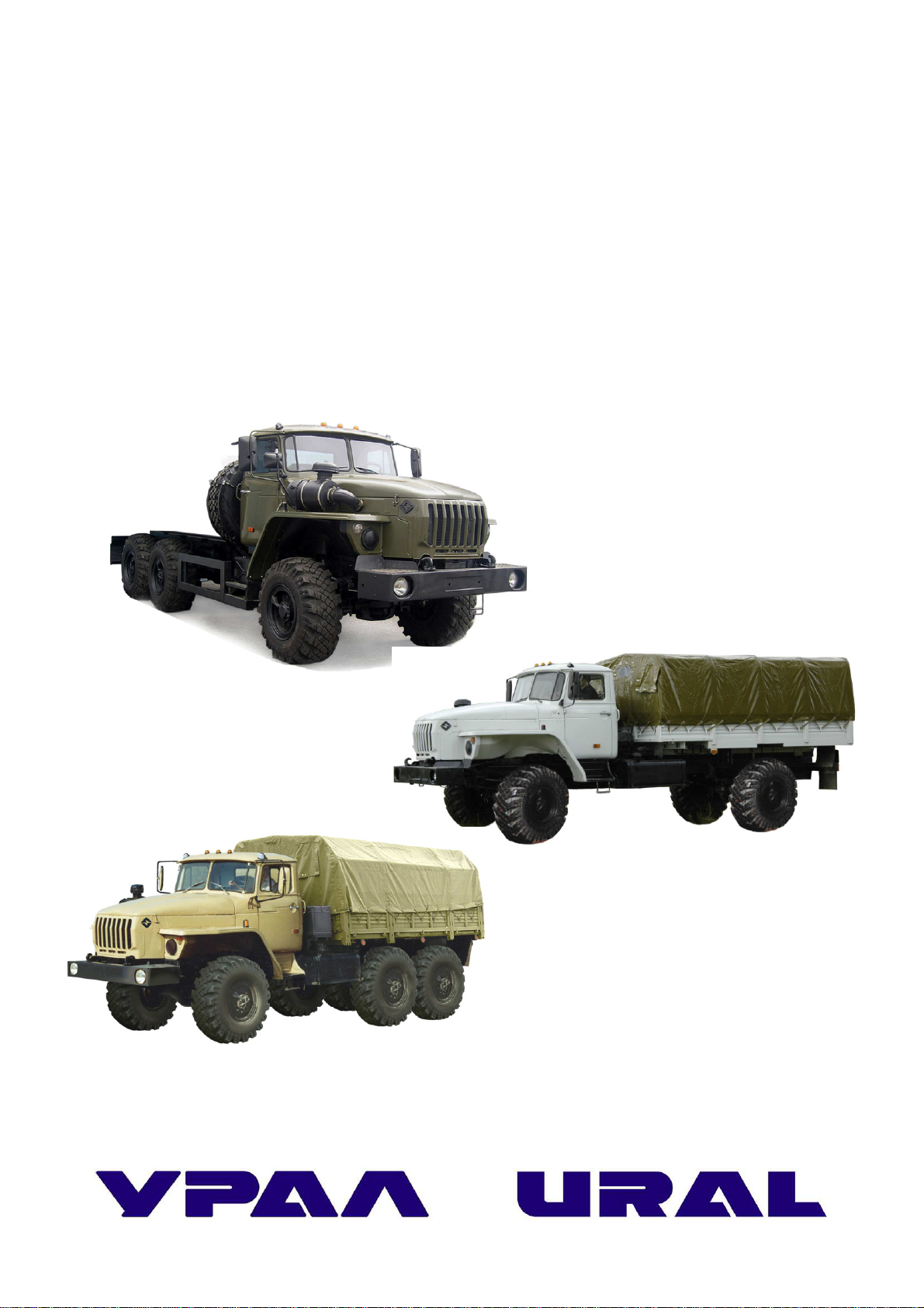
URAL Motorcycles URAL-4320-60 User manual

URAL-4320-60/61, URAL-43206-61, URAL-5557-60
TRUCKS
AND THEIR MODIFICATIONS

РДР №4588 от 19.12.2014г
URAL-4320-60/61, URAL-43206-61, URAL-5557-60
TRUCKS
AND THEIR MODIFICATIONS
Operation Manual
4320-3902037 РЭ
(First edition, revised)
© UralAZ
Reprinting, duplicating or translating
in whole or in part without written
permission of the «Ural» Automobile
Plant Open Joint-Stock Company is
prohibited
Miass – 2014

2
The Operation Manual is to be used by drivers and motor service staff involved in Ural
trucks operation. This Operation Manual includes the trucks technical specification, a brief de-
scription of the truck units and subunits, their adjustment and maintenance, and reference data.
Due to constant product improvement enhancing its reliability and operating conditions,
certain changes not included in this Manual may be made to the design.
When operating the trucks, use the present Operation Manual, Yaroslavl Motor Works
YAMZ-236НЕ2, YAMZ-236НЕ, YAMZ-236Н, YAMZ-236БЕ2, YAMZ-236БЕ, YAMZ-236Б
Power Units Operation Manual, and Addendum YAMZ-6565, YAMZ-65651, YAMZ-65652,
YAMZ-65653, YAMZ-65654 Engines and their configurations to the Operation Manual for
YAMZ-236НЕ2, YAMZ-236НЕ, YAMZ-236Н, YAMZ-236БЕ2, YAMZ-236БЕ, YAMZ-236Б
Power Units, Air Heater Specification and installation instruction, Storage Batteries Operation
Manual, Starting preheater Operation Manual, Gearbox Operation Manual, Tow unit 21-202 In-
stallation and Operation Manual, Tachograph Operation Manual.
Compiler: N. Tebenjkova
Editor-in-Chief: V. Trofimov

3
CONTENTS
1 Foreword . . . . . . . . . . . . . . . . . . . . . .. . . . . . . . . . . . . . . . . . . . . . . . . . . . . . . . . . . . . . . . . . . . . . . 4
2 Safety Requirements and Precautions. . . . . . . . . . . . . . . . . . . . . . . . . . . . . . . . . . . . . . . 9
2.1 Safety Requirements. . . . . . . . . . . . . . . . . . . . . . . . . . . . . . . . . . . . . . . . . . . . . . . . . 9
2.2 Precautions . . . . . . . . . . . . . . . . . . . . . . . . . . . . . . . . . . . . . . . . . . . . . . . . . . . . . . . 11
3 Specifications. . . . . . . . . . . . . . . . . . . . . . . . . . . . . . . . . . . . . . . . . . . . . . . . . . . . 15
4 Controls and Instruments. . . . . . . . . . . . . . . . . . . . . . . . . . . . . . . . . . . . . . . . . . . . . . . 33
5 Adjustment and Servicing of Truck Components (Brief Description) . . . . . . . . . . . . . . . . . . . . . . 38
5.1 Engine. . . . . . . . . . . . . . . . . . . . . . . . . . . . . . . . . . . . . . . . . . . . . . . . . . . . . . . . . . . . . . . . . 38
5.1.1 Fuel System. . . . . . . . . . . . . . . . . . . . . . . . . . . . . . . . . . . . . . . . . . . . . . . . . . . . . 38
5.1.2 Engine Starting Preheating System. . . . . . . . . . . . . . . . . . . . . . . . . . . . . . . . . . . . 41
5.1.3 Gas Exhaust System. . . . . . . . . . . . . . . . . . . . . . . . . . . . . . . . . . . . . . . . . . . . . . . 43
5.1.4 Cooling System. . . . . . . . . . . . . . . . . . . . . . . . . . . . . . . . . . . . . . . . . . . . . . . . . . 44
5.1.5 Power Unit Suspension . . . . . . . . . . . . . . . . . . . . . . . . . . . . . . . . . . . . . . . . . . . 46
5.2 Transmission . . . . . . . . . . . . . . . . . . . . . . . . . . . . . . . . . . . . . . . . . . . . . . . . . . . . . . . . . . . 47
5.2.1 Clutch Release Drive with Air-Hydraulic Booster. . . . . . . . . . . . . . . . . . . . . . . . 47
5.2.2 Transfer Case . . . . . . . . . . . . . . . . . . . . . . . . . . . . . . . . . . . . . . . . . . . . . . . . . 50
5.2.3 Cardan Drive . . . . . . . . . . . . . . . . . . . . . . . . . . . . . . . . . . . . . . . . . . . . . . . . . . 54
5.2.4 Driving Axles. . . . . . . . . . . . . . . . . . . . . . . . . . . . . . . . . . . . . . . . . . . . . . . . . . 57
5.3 Running Gear. . . . . . . . . . . . . . . . . . . . . . . . . . . . . . . . . . . . . . . . . . . . . . . . . . . . . . . . . . 66
5.3.1 Frame. . . . . . . . . . . . . . . . . . . . . . . . . . . . . . . . . . . . . . . . . . . . . . . . . . . . . . . . . . . 66
5.3.2 Truck Suspension. . . . . . . . . . . . . . . . . . . . . . . . . . . . . . . . . . . . . . . . . . . . . . 67
5.3.3 Wheels and Tires. . . . . . . . . . . . . . . . . . . . . . . . . . . . . . . . . . . . . . . . . . . . . . . . 74
5.3.4 Spare Wheel Holder . . . . . . . . . . . . . . . . . . . . . . . . . . . . . . . . . . . . . . . . . . . 83
5.4 Steering. . . . . . . . . . . . . . . . . . . . . . . . . . . . . . . . . . . . . . . . . . . . . . . . . . . . . . . . . . . . . 84
5.4.1 Steering . . . . . . . . . . . . . . . . . . . . . . . . . . . . . . . . . . . . . . . . . . . . . . . . . . . . . 84
5.4.2 Maintenance of Steering. . . . . . . . . . . . . . . . . . . . . . . . . . . . . . . . . . . . . . . . . 89
5.5 Brake Systems. . . . . . . . . . . . . . . . . . . . . . . . . . . . . . . . . . . . . . . . . . . . . . . . . . . . . . . . 92
5.5.1 Service Brake System. . . . . . . . . . . . . . . . . . . . . . . . . . . . . . . . . . . . . . . . . . . 92
5.5.2 Pneumatic Drive of Service Brakes . . . . . . . . . . . . . . . . . . . . . . . . . . . . . . . . . . . 101
5.5.3 Maintenance of Brakes Pneumatic Drive. . . . . . . . . . . . . . . . . . . . . . . . . . . . . . . . 113
5.5.4 Emergency Brake system. . . . . . . . . . . . . . . . . . . . . . . . . . . . . . . . . . . . . . . . . . 114
5.5.5 Parking Brake System. . . . . . . . . . . . . . . . . . . . . . . . . . . . . . . . . . . . . . . . . . . . 114
5.5.6 Truck Brake System with Anti-Lock Braking System (ABS). . . . . . . . . . . . . . . . 117
5.5.7 Auxiliary Brake System. . . . . . . . . . . . . . . . . . . . . . . . . . . . . . . . . . . . . . . . . . . . .
125
5.6 Electric Equipment. . . . . . . . . . . . . . . . . . . . . . . . . . . . . . . . . . . . . . . . . . . . . . . . . . . . . . . 127
5.6.1 Electronic Speedometer. . . . . . . . . . . . . . . . . . . . . . . . . . . . . . . . . . . . . . . . . . . . . 130
5.6.2. Electric Generator. . . . . . . . . . . . . . . . . . . . . . . . . . . . . . . . . . . . . . . . . . . . . . . . . 133
5.6.3. Storage Batteries. . . . . . . . . . . . . . . . . . . . . . . . . . . . . . . . . . . . . . . . . . . . . . . . . . 133
5.6.4 Lighting and Alarm System. . . . . . . . . . . . . . . . . . . . . . . . . . . . . . . . . . . . . . . . . . 134
5.7 Cab, Hood and Fender Assembly and Truck Platform Body . . . . . . . . . . . . . . . . . . . . . . .
138
5.7.1 Cab. . . . . . . . . . . . . . . . . . . . . . . . . . . . . . . . . . . . . . . . . . . . . . . . . . . . . . . . . . . . .
138
5.7.2 Hood and Fender Assembly . . . . . . . . . . . . . . . . . . . . . . . . . . . . . . . . . . . . . . . . . 143
5.7.3 Truck Platform Body. . . . . . . . . . . . . . . . . . . . . . . . . . . . . . . . . . . . . . . . . . . . . . .
143
5.8 Bolster Unit. . . . . . . . . . . . . . . . . . . . . . . . . . . . . . . . . . . . . . . . . . . . . . . . . . . . . . . . . . . . .
147
5.9 Special Equipment. . . . . . . . . . . . . . . . . . . . . . . . . . . . . . . . . . . . . . . . . . . . . . . . . . . . . . . .
151
5.9.1 Power Take-Off . . . . . . . . . . . . . . . . . . . . . . . . . . . . . . . . . . . . . . . . . . . . . . . . . . .
151
5.9.2 Auxiliary Power Take-Off . . . . . . . . . . . . . . . . . . . . . . . . . . . . . . . . . . . . . . . . . . 152
5.9.3 Winch . . . . . . . . . . . . . . . . . . . . . . . . . . . . . . . . . . . . . . . . . . . . . . . . . . . . . . . . . . 154
5.9.4 Tire Pressure Control System. . . . . . . . . . . . . . . . . . . . . . . . . . . . . . . . . . . . . . . . .
160
5.9.5 Sealing System. . . . . . . . . . . . . . . . . . . . . . . . . . . . . . . . . . . . . . . . . . . . . . . . . . . .
162
6 Possible Troubles and Methods of Trouble Shooting. . . . . . . . . . . . . . . . . . . . . . . . . . . . . . . . . . . .
163
7 Peculiar Features of Operation. . . . . . . . . . . . . . . . . . . . . . . . . . . . . . . . . . . . . . . . . . . . . . . . . . . . .
170
7.1 Preparing New Truck for Operation. . . . . . . . . . . . . . . . . . . . . . . . . . . . . . . . . . . . . . . . . . 170

4
7.2 Engine Start and Stop. . . . . . . . . . . . . . . . . . . . . . . . . . . . . . . . . . . . . . . . . . . . . . . . . . . . . 170
7.3 Running-in a New Truck . . . . . . . . . . . . . . . . . . . . . . . . . . . . . . . . . . . . . . . . . . . . . . . . . . 172
7.4 Driving Technique . . . . . . . . . . . . . . . . . . . . . . . . . . . . . . . . . . . . . . . . . . . . . . . . . . . . . . . 172
7.5 Truck Towing. . . . . . . . . . . . . . . . . . . . . . . . . . . . . . . . . . . . . . . . . . . . . . . . . . . . . . . . . . . 175
8 Maintenance. . . . . . . . . . . . . . . . . . . . . . . . . . . . . . . . . . . . . . . . . . . . . . . . . . . . . . . . . . . . . . . . . . . 177
8.1 Maintenance Categories. . . . . . . . . . . . . . . . . . . . . . . . . . . . . . . . . . . . . . . . . . . . . . . . . . . 177
8.2 Maintenance Schedule . . . . . . . . . . . . . . . . . . . . . . . . . . . . . . . . . . . . . . . . . . . . . . . . . . . . 177
8.3 List of Maintenance Operations. . . . . . . . . . . . . . . . . . . . . . . . . . . . . . . . . . . . . . . . . . . . . 180
8.4 Truck Lubrication . . . . . . . . . . . . . . . . . . . . . . . . . . . . . . . . . . . . . . . . . . . . . . . . . . . . . . . .
197
8.4.1 General . . . . . . . . . . . . . . . . . . . . . . . . . . . . . . . . . . . . . . . . . . . . . . . . . . . . . . . . . 197
8.4.2 Chart of Lubricants and Working Fluids. . . . . . . . . . . . . . . . . . . . . . . . . . . . . . . .
198
9 Storage. . . . . . . . . . . . . . . . . . . . . . . . . . . . . . . . . . . . . . . . . . . . . . . . . . . . . . . . . . . . . . . . . . . . . . . 220
10 Transportation . . . . . . . . . . . . . . . . . . . . . . . . . . . . . . . . . . . . . . . . . . . . . . . . . . . . . . . . . . . . . . . . 224
11 Salvaging . . . . . . . . . . . . . . . . . . . . . . . . . . . . . . . . . . . . . . . . . . . . . . . . . . . . . . . . . . . . . . . . . . . .
226
Appendices. . . . . . . . . . . . . . . . . . . . . . . . . . . . . . . . . . . . . . . . . . . . . . . . . . . . . . . . . . . . . . . . . . . . . 228

5
1. FOREWORD
1.1. Ural all-terrain trucks (4х4, 6х6), with YAMZ-65654 diesel engine, with a
three-seat, all-metal cab located behind the engine are intended for transporting cargoes, people
and towing trailers on all kinds of roads and terrain.
Ural-4320-0111-61 truck shown in Fig. 1 is intended for transporting various cargoes,
people and towing trailers on all kinds of roads and terrain.
Ural-4320-1151-61 chassis is intended for packaging specialties.
Ural-43203-1151-61 chassis is intended for mounting box van body.
Ural-4320-0911-60 truck with an enhanced base is intended for transportation of various
cargoes and people and for towing trailers on all kinds of roads and particular terrain.
Ural-4320-1951-60 special chassis with an enhanced base is intended for mounting
technological equipment and specialties (oilfield, crane, drilling, tankers, fire fighting, municipal
etc), towing trailers on all kinds of roads and particular terrain.
Ural-5557-1151-60, Ural-55571-1151-60 chassis shown in Fig. 2 are intended for
mounting various bodies and equipment.
Ural-43206-0111-61 truck shown in Fig. 3 is intended for transporting various cargoes,
people and towing trailers on all kinds of roads and terrain.
Ural-43206-1151-61 multipurpose chassis without a spare wheel holder is intended for
packaging specialties.
Ural-44202-0311-60 bolster truck is intended for towing semi-trailers on all kinds of
roads. Ural-44202-0511-60 bolster truck with a two-door cabin with a berth is intended for
towing semi-trailers on all kinds of roads.
Fig. 1 – Ural-4320-61 Truck

6
Fig. 2 – Ural-55571-60 Chassis
Fig. 3 – Ural-43206-61 Truck

7
The trucks are designed for operation at ambient temperatures ranging from +50 °C
down to –45 °C (a short-time operation at –50 °C).
The trucks meet the requirements of Specifications 37.165.404-2012 "Ural" 4x4, 6x6
Trucks".In case of using the trucks for other purposes, or with violations of operating instructions,
as well as introducing any design changes without the consent of the “URAL” Automobile Works
OE JSC, the manufacturer will not accept reclamations from customers or consider any claims.
The first overhaul period for the first category of the operational conditions in accordance
with the "Regulations on the maintenance and repair of rolling stock of automobile transport",
subject to all the rules specified in the Operation manual, for the trucks should be not less than: for
Ural-43206-61, Ural-5557-60, Ural-55571-60 vehicles and their modifications — 200 000 km, for
Ural-4320-60/61 vehicles and their modifications — 250 000 km.
During this period, the replacement of components and assemblies that have covered
their predetermined haulage is permissible, which is also valid for purchased items which resource
specified in the manufacturer plants technical documents and standards, is shorter than the vehicle
resource.
The trucks and chassis are available in various packaging for design variants and nomen-
clature of the components.
On the basis of the trucks and chassis various products (tank trucks, crane trucks, oil field
equipment, vans, etc.) are manufactured as well. All comments and proposals regarding their work
should be referred to manufacturers of those products).
It is allowed to use the trucks with pull-type systems which have air outlets and electric
outlets as per GOST 9200-76 (version II), the brake system air outlet as per GOST 4364-81 Stan-
dard, brake systems as per GOST 22895-77 Standard, a gross weight corresponding to the specifi-
cations, and drawbars: for trailers – a coupling pin having “A” diameter as per GOST 12017-81
Standard that is equal to 50.8 mm and mounting dimensions as per GOST 12105-74 Standard for
rated load on the fifth wheel over 83.3 kN (8.5 tf)2349 Standard or a coupling pivot as per GOST
R 41.55 Standard for semi-trailers having “A” diameter as per GOST; for trailers* — a trailer
hitch (drawbar eyelet) must comply with class D50 as per GOST R 41.55-2005 (for non-clearance
tow unit), basic dimensions must comply with GOST R 41.55-2005 Standard and ISO 1102-75.
Application of eyelets of other dimension is not allowed.
Mounting of various equipment and mechanisms onto the truck and its chassis is allowed
only after agreeing it upon with the Engineering Department of the “URAL” Automobile
Works. Otherwise, a customer shall be deprived to make any claims relating to premature failure
of truck components.
1.2. Marking of Ural trucks and chassis comprises the truck marking as a whole
transport means, marking of the chassis and cab and engine as constituent parts of the transport
means. The structure of the marking corresponds to a "Wheeled vehicles safety technical regula-
tion».
* Upon the Customer request it is technically feasible to install a towing coupler of «hook-loop»
type (delivered as spare parts to Ural vehicles) for using with trailers as per GOST 2349-75 dimension-type
3. The towbar (coupling hook lug) should correspond to GOST 2349-75.
The VIN identification number (or that of the chassis) is marked by impact method on
the back of the truck right side member:

8
- for 4х4 trucks (chassis) at the distance of 200-300 mm back from the rear axle and 40-
60 mm down from the sidemember upper flange;
- for 6х6 trucks (chassis) at the distance of 1000-1250 mm back from the bogie axis and
40-60 mm down from the sidemember upper flange.
The nameplate is attached to the r. h. panel of the cab side near the footstep. The name-
plate contains:
- manufacture trademark;
- identification number;
- modification;
- technically permissible maximum weight;
- technically permissible maximum axle loads;
- technically permissible gross combination weight;
- maximum load on fifth wheel arrangement load;
- Vehicle (chassis) Type Approval number.
To the left of the nameplate, the cab number is marked on the right panel of the cab in-
step plate. The marking contains 14 digits and is applied by hammering
Structure of the vehicle identification number and its explanation:
1 2 3 4 5 6 7 8 9 10 11 12 13 14 15 16 17
Х1 Р∗
∗
∗
∗
∗
∗
∗
∗
∗
∗
∗
∗
∗
∗
∗
- Variable data
Item 1-3
Х1Р– “URAL” Automobile Works” JSC, Miass, Chelya
binsk Region,
Russia (manufacturer’s international identification code)
Item 4-9
Product designation
Item 10
Year of manufacture
Item 11-17
Serial production number of vehicle
Letters used for indicating the year of manufacture:
D - 2013 F-2015
E - 2014 G - 2016
Data on engine marking are given in «YAMZ-236НЕ2, YAMZ-236НЕ, YAMZ-236Н,
YAMZ-236БЕ2, YAMZ-236БЕ, YAMZ-236БPower Units» Operation Manual, «YAMZ-6565,
YAMZ-65651, YAMZ-65652, YAMZ-65653, YAMZ-65654 Engines and their configurations»
Addendum to the Operation Manual «YAMZ-236НЕ2, YAMZ-236НЕ, YAMZ-236Н, YAMZ-
236БЕ2, YAMZ-236БЕ, YAMZ-236БPower Units».

9
2 Safety requirements and precautions
2.1 Safety requirements
2.1.1 Before you start working, make sure that the truck and its coupling devices are in
good working order.
2.1.2 While driving the vehicle, the driver and passengers must wear seat belts.
2.1.3 Do not start the truck engine, without making sure that the gearbox is in neutral.
2.1.4 Service and repair the truck on a level ground, after having braked the parking
brake by disconnecting the batteries using the switch and placing wheel chocks under the wheels.
2.1.5 Keep the engine and starting preheater clean and maintain their working order,
make sure there are no fuel and oil leakages: this may cause fire. During the preheater operation,
do not leave the vehicle unattended.
2.1.6 In the process of filling the truck with fuel, the pre-heater must be switched off.
2.1.7 Do not warm up the engine, if the truck is indoors, and ventilation is poor.
2.1.8 Coolants (low-freezing) and brake fluids are toxical: handle with care.
2.1.9 To climb the truck front bumper and descend it, use the step plate, central and left-
most (in direction of travel) grille ribs having on the inserts on the inner side, as shown in Figure
4. 2.1.10 When servicing the engine, fix the hood lifting mechanism with a safety hook 1
(Fig.5). 2.1.11 Before dismantling the wheel put the wheel chocks under the unlifted axle wheels
in order to avoid the vehicle self-motion. Unfasten the wheel nuts, hang out the wheel with jack or
other hoisting device, unscrew the nuts and dismantle the wheel.
To lift the front axle with the jack, insert its screw head in the spring clamp socket; to lift
the rear axle – under the spring supporting bracket.
1- safety hook
Fig. 5 - Hood Lifting
Mechanism Safety Lock
Fig. 4 - How to Use Step and Radiator Grill Ribs,
When Climbing Bumper and Coming Down It

10
2.1.12 It is prohibited to remove any wheel from the truck, if all air has not been let out
of its tyre before.
2.1.13 It is prohibited to mount a just assembled and uninflated wheel with its tire onto
the truck and inflate the tire using the tire inflation system.
2.1.14 The manufacturer draws your special attention to strict compliance with
safety regulations changing / mounting the wheel (see «Wheels and Tires» Section).
2.1.15 While lowering the spare wheel, keep yourself out of reach of the wheel holder
hinged bracket.
2.1.16 Before the truck full stop, it is prohibited to remove the ignition key out of the ig-
nition lock, because this leads to loss of control of the truck due to a steering shaft lock by an anti-
theft device.
2.1.17 It is prohibited to use the truck without lock spring ring 14 (See Fig.118) and
winged nut 5 of the storage battery compartment cover.
2.1.18 To avoid falling down the storage batteries in the course of their servicing on the
truck move the battery out of the container only on the container hinged cover, make sure it is
fixed securely in its horizontal position.
2.1.19 In case of electrolytic solution contact with skin, within 5-10 min it is necessary to
rinse the affected area with abundant jets of water and moisten with 10% liquid ammonia aqueous
solution and then with a weak solution of soda.
2.1.20 Check condition of the insulation of the wire from “+” battery terminal to the
starter: damaged insulation can cause fire.
2.1.21 Perform welding on the truck, observing fire safety measures. When carrying out
electric welding disconnect wires from the generator, batteries and electronic control units, to
protect the plastic pipes and fuel lines from damage. Connect the welder ground conductor close
to the weld spot, having prevented the electric current passing through bearings and friction pairs.
2.1.22 When moving upgrade, it is necessary to select the required gear in advance.
2.1.23 When transporting passengers, fix the right door lock of the cab 4 as shown in
Figure 116.
2.1.24 Hitch and unhitch the trailer (semi-trailer) on an even flat site.
2.1.25 When using the winch:
- do not stay under the cargo to be transferred as well as close to the tensioned rope;
- avoid kinks or knots on the rope as they can result in its damage and break. When
extending the rope across the road, put a guard and warning signs prohibiting to pass.
2.1.26 When using the independent air heater keep in mind that the heater mishandling,
as well as heater failures, are the sources of extreme fire danger and may cause exhaust fumes
poisoning.
Prohibited:
- leaving the working heater unattended;
- using the heater with faulty wiring (electric junction sparking);
- using the heater when the inlet and exhaust branches are partially or completely over-
lapped; - opening the case top cap when the heater is working and touch the hot components;

11
- placing explosive and inflammable substances or devices (e.g. spray bottles, etc.) in the
heater heat flow area;
- using the heater in an unaired area;
- using the heater with the damaged fuel supply system;
- starting and using the heater poured over with fuel;
- switch on heating when transporting flammable cargoes at temperatures above minus
5°Сin order to avoid fire;
- switching on and using the heater near gas-filling stations and other places with in-
flammable vapors or significant amounts of explosive dust (carbon, wood dust, etc.) in the air.
Keep the independent air heater switched off at gas-filling stations and during fuel tank-
ing. In case of the fuel ignition, switch off the independent air heater immediately and use the
fire extinguisher if necessary.
Attention! Do not extinguish burning fuel with water.
2.1.27 If burnout loss signs or fuel and combustion products smell is detected in the cab,
switch off the heater. Further operation of the heater is possible after removing the causes occa-
sioned the exhaust gases penetration in the cab.
2.2. Precautions
Proper operation of the truck and its long service life can be ensured if you observe all
recommendations given in this Manual.
2.2.1 Before operating the truck, you should carefully read the section "PRECAU-
TIONS", "SAFETY REQUIREMENTS".
2.2.2 When running the first 1000 km (50 hours of engine operation), comply with the
rules described in Section “New Truck Running-in”.
2.2.3 Before starting the engine, you must carefully read the section "Power unit start,
operation and stop" of the power units operating manual.
2.2.4 To prevent air penetration in the fuel feed system do not burn all the fuel from the
fuel tank.
2.2.5 See that the preheater fuel pump is adjusted correctly, not allowing open flame in
the gas conduit of the heat exchanger.
2.2.6 Do not allow the preheater to operate for more than 15 sec without a coolant in the
heat exchanger. Upon washing the truck or its fording, engage the pump unit for 2-3 min to re-
move water from the preheater air duct.
2.2.7 Warm up the engine till switching on all the cylinders and changing the engine
speed when changing the fuel supply; start travelling at low gear.
It is recommended after the engine start for its uniform heating and increasing the tem-
perature in the cab, start traveling at low gear after the coolant has been heated up to 40 °C.
The optimum temperature of the working engine coolant should be 75-100 °C.

12
2.2.8 To drain the fluid from the engine cooling system completely, place the truck on a
flat site or incline it forward.
2.2.9 Drain the coolant from the engine cooling system through three cocks (on the heat
exchanger, on the pump unit and on the water pump inlet branch) with the open cab heater cock
and the open plugs of the radiator and preheater filling pipe. If water is used in the engine cooling
system in an emergency situation, remove the rest of water from the preheater liquid pump by en-
gaging the pump unit for 10-15 sec to avoid the fan impeller freezing-on. Upon draining the fluid,
close the cocks.
2.2.10 Transfer gearbox and rear axles differential lock switches should be in «off» posi-
tion when the differentials are unlocked.
2.2.11 Shifting gears in the transfer case is only allowed after the vehicle full stop.
2.2.12 Cross-axle differential locking is to be used in certain conditions only as per
«Truck Driving» Section.
2.2.13 Lock and unlock differentials after the vehicle has been completely stopped. If the
differentials failed to lock, it is necessary to pull away smoothly and drive the vehicle at a speed
not exceeding 5 km / h till the differentials lock, performing the interaxle differential locking.
2.2.14 With a cross-axle differential locked, drive the vehicle at speed not exceeding 20
km/h on the straight only.
1.2.15 When driving out of a rut, do not go for a long time with the steering wheel turned
in the extreme position since oil can be overheated in the hydraulic system and the pump may be
broken. For the same reason, when taking off power in steady-state condition, release the steering
control shaft by turning the steering wheel until it turns freely.
It is recommended to set the steering gear sliding valve to the neutral position in the fol-
lowing order:
- when the engine is running turn the front wheels to the extreme left or to the extreme
right position and release the steering wheel;
- stop engine;
- after wheels partial self-return, set the steering wheel to the middle position within free
motion at that wheels position.
Having performed these actions the engine can be started and the vehicle can be operated
in steady-state conditions.
2.2.16 Before the truck starts travelling, the air pressure in the brake system should be
not less than 440 kPa (4,7 kgf/cm
2
). If alarm lamp 3 (see Fig.20) on the dashboard turns on, rem-
edy a fault occurred in the pneumatic part of the drive.
2.2.17 Before travelling, check if the alarms of the pilot lamp assemblies (see Fig. 20) are
in good working order 9.
2.2.18 Do not use the truck with the lowered tailgate, because in this position it closes the
rear signalling lights.
2.2.19 If the engine has not been started or has stalled by any reasons, first set the key
into its initial upright position, than switch on the starter in 1–2 min.
2.2.20 Frequent starting of the engine with its short-term operation result in quick dis-
charge of the storage battery.

13
2.2.21 Do not move the truck using the starter: this may cause starter breakdown and
quick storage batteries discharge.
2.2.22 To avoid generator breakdown attach the starter cable to the positive terminal of
the storage battery and attach the storage battery switch cable to the negative terminal..
2.2.23 Attach cables to the generator set according to the marking.
2.2.24 Prior to removing the generator from the engine switch off the storage battery.
2.2.25 During long-term parking of the truck disconnect the storage battery from the
“ground” with the help of the “ground” switch button 37 (see Fig. 18).
2.2.26 When starting the engine from an external source, it is required to switch on the
storage battery. It is prohibited to use a direct-current source with ratings exceeding 24 V at a cur-
rent of 0 (zero) A and 18.3 V at a current of 1000 A and the storage battery that has a rated capac-
ity different from 190 A.h by more than
+
20 A.h.
2.2.27 Removal of the seals from the speedometer and speedometer sender in the warran-
ty period without the permission of the manufacturer drive flexible shaft deprives a customer to
make any claims.
2.2.28 At an ambient temperature lower than –25 °C use an auxiliary power take-off
only after a short run (approximately 15 km) or warming-up of the oil in the transfer box by oth-
er method, for example, by hot air.
2.2.29 During the truck travelling the wheel valves of the tire pressure control system
should be opened. When the truck has been parked for a long time, close the wheel valves. At an
ambient temperature lower that –35 °C open the wheel valves 15–20 km after beginning of travel.
Upon opening the wheel valves blow through the tire pressure control system with the air from the
tires (see the Section “Central Tire Pressure Control System”).
2.2.30 When towing, in order to avoid the gearbox failure, engage the neutral gear in the
transfer gearbox. Towing is performed limiting the maximum towing speed to 50 km/h.
2.2.31 Manoeuvring, particularly while reversing, do not allow big angles of the road
train folding to avoid damage of the drawbar.
2.2.32 When using a trailer at an ambient temperature less than -25 °C, do not leave the
rubber buffer of the drawbar under load before a long parking to avoid freezing of the pressed
rubber bumper and appearing an axial clearance in the drawbar. Disconnect the trailer or unload
the axial load from the rubber buffer by moving the truck forwards and backwards.
2.2.33 When a loader having a total weight exceeding 3200 kg is running onto the truck
platform, put shields (boards) under its wheels.
2.2.34 Put heavy small-sized cargoes, which can cause local sagging of the platform floor
or damage the body sides and seat components, onto sills (boards) and fix them securely. Place
the cargo so that its centre of inertia is located in the middle of the truck platform.
2.2.35 If after parking the truck for a long time or for the reason of high air leaks, the
complete air leakage occurred and the gear is engaged, it is necessary to disengage the gear (set-
ting in the neutral position) by alternate turning the engine crankshaft to the right and left through
approximately 180
o
, using the technique described in the Section “Adjustment of Valve Timing
Mechanism” of the engine Operation manual or release the clutch by filling the pneumatic system
by the compressed air with the help of another truck via the towing valve.

14
2.2.36 Transportation of goods or towing trailers (or transport means) exceeding the max
weights indicated in the Operation Manual is not admissible.
2.2.37 After a long-term travelling in snowfall conditions or on snow-covered roads —
remove the air filter cover and shake out the snow from the filter compartment.
2.2.38 When operating the truck with a trailer it is not admissible to:
- use a towing coupler on GOST Р41.55-2005, if the control pin projects relative to the
handle (see the Installation and Operation Instructions «Towing coupler 21-202», Section «Opera-
tion and description», subsection «Coupling control»).
- use a towing coupler on GOST 2349-75 with unsecured latch of the towing hook by the
locking pin (see «Running Gear» Section).
2.2.39 Using tires of different manufacturing plants on the same truck is not admissible.

3 Specifications
3.1 Basic parameters and dimensions
3.1.1 Basic parameters are given in Table 1 and 2.
Table 1 - 6х6 Trucks basic parameters
Parameters Ural-
4320-
0111-61
Ural-
4320-
1151-61
Ural-
43203-
1151-61
Ural-
4320-
0911-60
Ural-4320-
1951-60 Ural-5557-
1151-60 Ural-
55571-
1151-60
Ural-
44202-
0311-60
Ural-
44202-
0511-60
General data
Payload, kg
6000
-
-
10 000
-
-
-
-
-
Payload on chassis, kg - 6875 6845 - 12 000 12 000/
9000* 12 000 - -
Truck (chassis) bare weight,
kg 8940 8000/
8500*
1
8285 - 8520 8335 8410 8640 8765
Total vehicle weight with
cargo, driver and passengers (225
kg) disregarding the curb weight
tolerance, kg
15 165
15 100/
17 300*
2
15 355/
17 300*
2
21 300*
2
20 745/
21 300*
2
20 560/
21 300*
2
20 635/
21 300*
2
19 865/
14 215*
19 990/
14 340*
Gross trailer (semitrailer)
weight, kg
11 500/7000*
11 500/7000*
11 500
19 100/12 500*
Weight distribution of empty
truck (chassis) with additional
equipment and outfit, kg:
on the front axle 4710 4540 4685 4900 4860 4350 4695 4765 4830
on rear bogie
4230 3460 3600 4740 3660 3985 3715 3875 3935
15

Table 1 continuation
Parameters Ural-
4320-
0111-61
Ural-
4320-
1151-61
Ural-
43203-
1151-61
Ural-
4320-
0911-60
Ural-4320-
1951-60 Ural-5557-
1151-60 Ural-
55571-
1151-60
Ural-
44202-
0311-60
Ural-
44202-
0511-60
Gross vehicle weight distri-
bution, kg:
on the front axle 4910
5060/
5300*
2
4970/
5300*
2
5300*
2
5260/
5300*
2
5090/
5300*
2
5275/
5300*
2
5725/
4265* 5190/
4300*
on rear bogie 10 255 10 040/
12 000*
2
10 390/
12 000*
2
16 000*
2
15 490/
16 000*
2
15 885/
16 000*
2
15 360/
16 000*
2
14 740/
9950* 14800/
10 040*
Operational data
Maximum travelling speed
at gross weight, km/h
80
Truck (chassis, bolster truck
(road train) ) estimated fuel con-
sumption*3 at speed of 60 km/h per
100 km, l, max
36
40
37
36
47
Cruising range on truck
(chassis) control fuel consumption
at a speed of 60 km/h, km
572 (fuel tank 210 l)
816 (fuel tank 300 l) 515 (fuel tank 210 l)
785 (fuel tank 300 l) 730
Braking distance with GVW
when travelling at a speed of 60
km/h, m, max
36,7
Maximum ascent at GVW,
degrees, (%), no less than
60 (31)
27 (15)
18 (11)
The least turning radius on
the front outer wheel track axis
(relative to the turning center), m,
max
11,5
13,0
11,5
-
16

Table 1 continuation
Parameters Ural-
4320-
0111-61
Ural-
4320-
1151-61
Ural-
43203-
1151-61
Ural-
4320-
0911-60
Ural-4320-
1951-60 Ural-5557-
1151-60 Ural-
55571-
1151-60
Ural-
44202-
0311-60
Ural-
44202-
0511-60
Fordability
(
hard
#
bottom ford) at natural wave
(not produced by the truck), m
0,7
Engine
Model, type
YAMZ-65654, ignition by compression, four-stroke, turbocharged, 6-cylinder -engine
Operating capacity, l
11,15
Rated
capacity
,
kW
(hp),
no less than
169(230)
Maximum torq
ue,
gross, N.m (kgf·m), no less
than
882(90)
Nominal s
peed, min
-
1
2100
50
20
+
−
Rpm corresponding to
themax torque, min
-1
1100-1500
Engine lubricating system
Mixed
,
under
pressure
with
injection
and
with
the
oil
cooling
in
the
liquid
-
to
-
oil
heat
e
x-
changer
Engine feed system
Main fuel tank, l
210 (refill capacity 206) or
300 (refill capacity 294)
Engine air feed system
with
dry
air
filter
with
the
replaceable
cardboard
filtering
element
,
air
-
cooling
and
with
a
contamination indicator
Exhaust system
with the release from the turbo-charger backwards, pipeline with wearproof (auxiliary) brake,
noise suppressor, the end of the exhaust pipe is directed to the truck axis
17

Table 1 continuation
Parameters Ural-
4320-
0111-61
Ural-
4320-
1151-61
Ural-
43203-
1151-61
Ural-
4320-
0911-60
Ural-4320-
1951-60 Ural-5557-
1151-60 Ural-
55571-
1151-60
Ural-
44202-
0311-60
Ural-
44202-
0511-60
Cooling system
hydronic, closed
-
type with forced
-
circulation of liquid coolants.
Corrugated
-
vane
radiator
Transmission
Clutch YAMZ-183-15, friction clutch, dry, single-disk with a pull-out diaphragm spring, asbestos-free clutch lin-
ings, hydraulically operated, pneumo-hydraulic booster
Gearbox YAMZ-2361, mechanical, three-throw, five-gear, with speed synchronizers for the second, third, fourth and
fifth gear
gear ratios first gear-5,22; second gear-2,90; third gear-1,52; fourth gear-1,00 fifth gear-0,664 or 0,71; reverse-5,22
Transfer gearbox
gear ratios
Mechanical, two-step blocked interaxle differential distributing the torque between the front and the rear
axle with the 1:2 ratio, with the front axle drive
high gear ,)-)1,04
,-).
+
Exposed, with four shafts, joints on the needle bearings
Axles Driving, combined axle case consists of a cast middle part and half-axle casings pressed in it. The front axle
is a steerable one, with constant velocity joints of disk-type
Main gear
Double, drive-through type, two conical spiral tooth gears and two cylindrical skew gears. Main gears of all
axles are interchangeable
Differential is symmetrical, conical with four pinions. Semi axles are fully offloaded, spline joint with the
hub
gear ratio 7,49
Running gear
Frame Stamped, riveted
Towing devices In the front: rigid towing hooks, in the rear: double-action towing unit
Truck suspension:
front
Conventional suspension on two semi-elliptic springs, operating jointly with two bilateral hydraulic snubbers
rear Conventional balancing suspension with torque rods, on two longitudinal semi-elliptic springs
18

Table 1 continuation
Parameters Ural-
4320-
0111-61
Ural-
4320-
1151-61
Ural-
43203-
1151-61
Ural-
4320-
0911-60
Ural-4320-
1951-60 Ural-5557-
1151-60 Ural-
55571-
1151-60
Ural-
44202-
0311-60
Ural-
44202-
0511-60
Wheels
515
-
254 (254
Г
-
508)
disk
split wheels with divided semi-deep
rim, having toroidal bead seats, cen-
tered at the chamfers of the clamp-
ing holes, wheel offset 120 mm
533-310 (310
-
533)
533
-
310 (310-533) disk wheels with divided
semi-deep rim, having toroidal bead seats, centered at the chamfers of the
clamping holes, wheel offset 100 mm
Tires 14.00-20, 146G (НС14/PR14)
model ОИ-25 pneumatic, tubed,
conventional profile, with heavy-
duty tread pattern, adjustable tire
pressure, max admissible load 30,40
kN (3100 kgf)
According to the truck package:
а) 425/85R21 156G, (НС16/PR16) КАМА-1260 (with heavy-duty
tread pattern) or model КАМА-1260-1 (with versatile tread pattern), pneu-
matic, radial, tubed, wide-section, with, controllable tire pressure, max ad-
missible load 39,46 kN (4000 kgf) or
б) 425/85R21, 156J (НС18/PR18) m О-184 pneumatic, tubed, con-
ventional profile, with heavy-duty tread pattern, with controllable tire pres-
sure, max admissible load 39,46 kN (4000 kgf) or
в) 425/85R21 156G, (НС16/PR16) Бел-1260, pneumatic, radial,
tubed, with heavy-duty tread pattern, with controllable tire pressure, max
admissible load 39,46 kN (4000 kgf)
Spare wheel holder location Vertical, behind the cab*
5
or secured by means of the technological service support -
Steering
Type of transmission Mechanical, with hydraulic booster
Steering gear (type, marking) MAZ – 64229 or RBL C-700 (Germany), «screw – ball nut-rack-sector» with hydraulic booster (for RBL C-
700), steering drive with hydraulic booster (for MAZ – 64229)
Booster unit Hydraulic, double-action type
Booster unit pump Blade, double-action, rotor type, driven by engine crankshaft
19
This manual suits for next models
3
Table of contents
Other URAL Motorcycles Truck manuals