manuals.online logo
Brands
  1. Home
  2. •
  3. Brands
  4. •
  5. ESD SYSTEMS
  6. •
  7. Test Equipment
  8. •
  9. ESD SYSTEMS 41220 Installation and operating instructions

ESD SYSTEMS 41220 Installation and operating instructions

Multi-Range Tester
Installation, Operation, and Maintenance
Features
• Tests static dissipative shoes per
ANSI-Z41 Standard
• Tests foot grounders
• Tests wrist straps and coil cords
• Fast response - detects intermittent
failures in wrist straps and coil
cords
- All types
- When being worn (system tests)
- When not being worn
- Detects intermittent failures such
as connection to resistor
• 30 VDC test voltage
• Verifies outlet’s polarity and
ground integrity
• Audible and visual indication
PS-2094 7/05 Page 1 of 4
Description
The ESD Systems.com 41220 Wrist
Strap/Footwear Tester is a versatile,
low-cost test instrument which
confirms the integrity and safety of
the static discharge path from the
operator to earth ground via wrist
strap and foot grounding systems.
This product can be used as one of
the tools to fulfill the ANSI ESD
S20.20 paragraph 6.1.3.2
“Compliance Verification Plan.
Verification should include routine
checks of the Technical
Requirements of the Plan.” By
touching the test button on the
Multi-Range Tester, a person can
quickly and easily ensure that his/her
wrist strap or foot grounding system
contains adequate current limiting
resistance and that there is continuity
from one’s skin to earth ground. The
Model 41220 also detects
excessively dry skin, poorly fitting
wrist straps, and intermittent wrist
straps and coil cords.
The Model 41220 includes a number
of innovations:
•Outlet Wiring Verification:
When plugged into an AC outlet
the yellow lamp lights if the
polarity is correct and the path to
earth ground via the equipment
ground (green or green and
yellow wire) is intact. If either
condition isn’t met, the alarm
sounds continuously.
•Detects intermittent wrist straps
and coil cords: Coil cords and
fabric wrist straps often become
intermittent before they fail
completely.
•30 VDC Test Voltage: This is
sufficient to overcome the
inaccuracies of 9 volt battery-
powered wrist strap testers and
high enough to comply with the
ANSI-Z41 standard for Static
Dissipative Shoes.
•Transient and Noise Immunity:
Circuitry is impedance protected
from line conducted voltage and
current transients and surges.
General Instructions
In the following test configurations,
the 41220 can be used to test wrist
straps, foot grounders, or shoes
while they are worn. Model 41213
will also allow the user to test
footwear.
Tech Brief
Figure 1. ESD Systems.com Multi-Range Tester, Item No. 41220
Made in America
© 2005 DESCO INDUSTRIES INC.
Employee Owned
WRIST STRAP TESTING WITH
MODEL 41220
This test safely checks that a
continuous path between the
operator, wrist strap and coil cord
exists.
A. While wearing the wrist strap
snugly on wrist, plug the banana
plug end of the cord into the jack on
the face of the unit.
B. Switch toggle switch toward
“WRIST STRAP”.
C. Touch the test button so that the
unit activates. Hold for 2-3 seconds
while flexing coil cord area near
resistor. Audio “chirping indicates
intermittents. Note: Often the initial
intermittency will be failure of strain
relief connection to resistor as
simulated by ESD S1.1-1998
paragraph 5.7 Bending Life Test.
Note: DO NOT TOUCH ANY
OTHER METAL WHILE
PERFORMING TEST.
Figure 2. Testing of wrist strap
grounding assemblies.
D. Lighting of the green “PASS”
LED indicates that the wrist strap
and ground cord assemblies are
functioning properly.
E. If either “FAIL LO” or “FAIL
HI” LEDs light, the wrist strap
wearer should investigate the cause
of the failure.
TESTING FOOT GROUNDING
DEVICES WITH MODEL 41220
AND 41213 FOOTPLATE
Conductive shoes or foot grounders
should be worn on both feet. Test
each foot separately to ensure proper
operation and complete protection.
A. Place the Footplate on the floor
in front of the Multi-Range Tester.
B. Plug the plate’s ground cord into
the jack on the left hand side of the
unit.
Figure 3. Testing foot grounding
devices with the 41220/41213
C. Switch toggle switch to “FOOT
STRAP” OR “SHOE”, as
appropriate.
D. Place one foot on the plate. If the
floor is conductive, you may need to
lift the foot you are not testing off of
the floor during this test. Make sure
there is no cord plugged into the
“WRIST STRAP” jack.
E. Touch the test button so that the
unit activates. Hold down for 2-3
seconds.
F. Lighting of the green “PASS”
LED indicates that the foot ground
assemblies are functioning properly.
G. If either “Fail LO” or “Fail HI”
LEDs light, the wearer should
investigate the cause of the failure.
H. Repeat steps C through G with
other foot.
ASSEMBLY OF THE 41226
STAND
The 41226’s rugged steel pedestal
tube is powder coated in a non-
conductive white finish that helps to
prevent false readings if contacted
by skin or loose smocks.
Figure 4. Attaching pedestal to
baseplate
Assembly
A. Remove 3 screws from baseplate.
B. Position pedestal on the baseplate
with the Tester mounting bracket
sloping toward the operator. Attach
pedestal to baseplate using the three
screws provided. Tighten with hex
wrench provided.
B. Attach poster to the wall at eye
level in front of the Tester location.
C. Attach ring terminal end of small
cord supplied under thumb screw.
PS-2094 Page 2 of 4 © 2005 DESCO INDUSTRIES INC.
Employee Owned
D. Install the Tester on the bracket
by aligning keyholes on the back of
tester with mounting studs on
bracket. While pushing up on thumb
screw, insert the mounting studs into
the keyholes and slide the tester
down. See Figure 4.
E. Twist the thumb screw clockwise
to secure the tester to the bracket.
F. Attach banana plug from small
cord to jack marked “FOOTPLATE”
on tester.
Figure 4. Installing tester on bracket
and securing tester to bracket
TESTING FOOT GROUNDING
DEVICES WITH MODEL 41220
Conductive shoes or foot grounders
should be worn on both feet. Test
each foot separately to ensure proper
operation and complete protection.
A. Switch toggle switch to “FOOT
STRAP” OR “SHOE”, as
appropriate.
B. Place one foot on the plate. If the
floor is conductive, you may need to
lift the foot you are not testing off of
the floor during this test. Make sure
there is no cord plugged into the
“WRIST STRAP” jack.
THUMB SCREW
C. Touch the test button so that the
unit activates. Hold down for 2-3
seconds.
D. Lighting of the green “PASS”
LED indicates that the foot ground
assemblies are functioning properly.
E. If either “Fail LO” or “Fail HI”
LEDs light, the wearer should
investigate the cause of the failure.
F. Repeat steps A through E with
other foot.
Figure 5. Testing foot grounding
devices with the 41220
PS-2094 Page 3 of 4
Specifications:
Operating Voltage
100-240 VAC, 50/60 Hz
Current Drain <20mA
Test Voltage, Open Circuit 30 VDC
Equipment Ground Resistance
Limit 1 kilohm
Resistance Limits, Wrist Strap
750 kilohms to 10 megohms
Resistance Limits, Foot Strap
750 kilohms to 35 megohms
Resistance Limits, Shoes
750 kilohms to 1 gigohm
Tolerance On All Limits ±10%
Size 1 x 5 x 7"
(2.54 x 12.7 x 17.78cm)
Weight 1 lb
Line Cord 5' long, 18-3 AWG
Calibration
The model 41220 is calibrated to
NIST traceable standards. We
recommend that calibration is
performed annually to ensure that
the Tester is operating within limits.
We offer a calibration unit that is
specifically designed to simplify the
calibration procedure. This unit is
sold as item 41230. The Calibration
Unit comes calibrated to NIST
traceable standards. For additional
information on the 41230, ask for
Tech Brief PS-2006.
Consider adding the 41220 to your list
of “test equipment that shall be selected
to make measurements of appropriate
properties of the technical requirements
that are incorporated into the ESD
program plan” as required by
paragraph 6.1.3.1 of ANSI/ESD S20.20.
© 2005 DESCO INDUSTRIES INC.
Employee Owned
PS-2094 Page 4 of 4
Visit our online
library of Tech Briefs:
http://www.esdsystems.com
432 NORTHBORO ROAD CENTRAL
MARLBORO, MA 01752-3170
PHONE (508) 485-7390
FAX (508) 480-0257
Limited Warranty
ESD Systems.com expressly warrants that for a period of one
(1) year from the date of purchase, Multi-Range Testers will be
free of defects in material (parts) and workmanship (labor).
Within the warranty period, a unit will be tested, repaired, or
replaced at our option, free of charge. Call Customer Service at
508-485-7390 for Return Material Authorization (RMA) and
proper shipping instructions and address. Include a copy of
your original packing slip, invoice, or other proof of date of
purchase. Any unit under warranty should be shipped prepaid
to the ESD Systems.com factory. Warranty replacements will
take approximately two weeks.
Warranty Exclusions
THE FOREGOING EXPRESS WARRANTY IS MADE IN
LIEU
OF ALL OTHER PRODUCT WARRANTIES,
EXPRESSED AND IMPLIED, INCLUDING MER-
CHANTABILITYAND FITNESS FOR A PARTICULAR
PURPOSE WHICH ARE SPECIFICALLY DISCLAIMED.
The express warranty will not apply to defects or damage due
to accidents, neglect, misuse, alterations, operator error, or
failure to properly maintain, clean or repair products.
Limit of Liability
In no event will ESD Systems.com or any seller be responsible
or liable for any injury, loss or damage, direct or consequential,
arising out of the use of or the inability to use the product.
Before using, users shall determine the suitability of the
product for their intended use, and users assume all risk and
liability whatsoever in connection therewith.
DRILL PATTERN
FOR
MULTI-RANGE
TESTER
ACTUAL SIZE
2.4"
4.1"
© 2005 DESCO INDUSTRIES INC.
Employee Owned

Other ESD SYSTEMS Test Equipment manuals

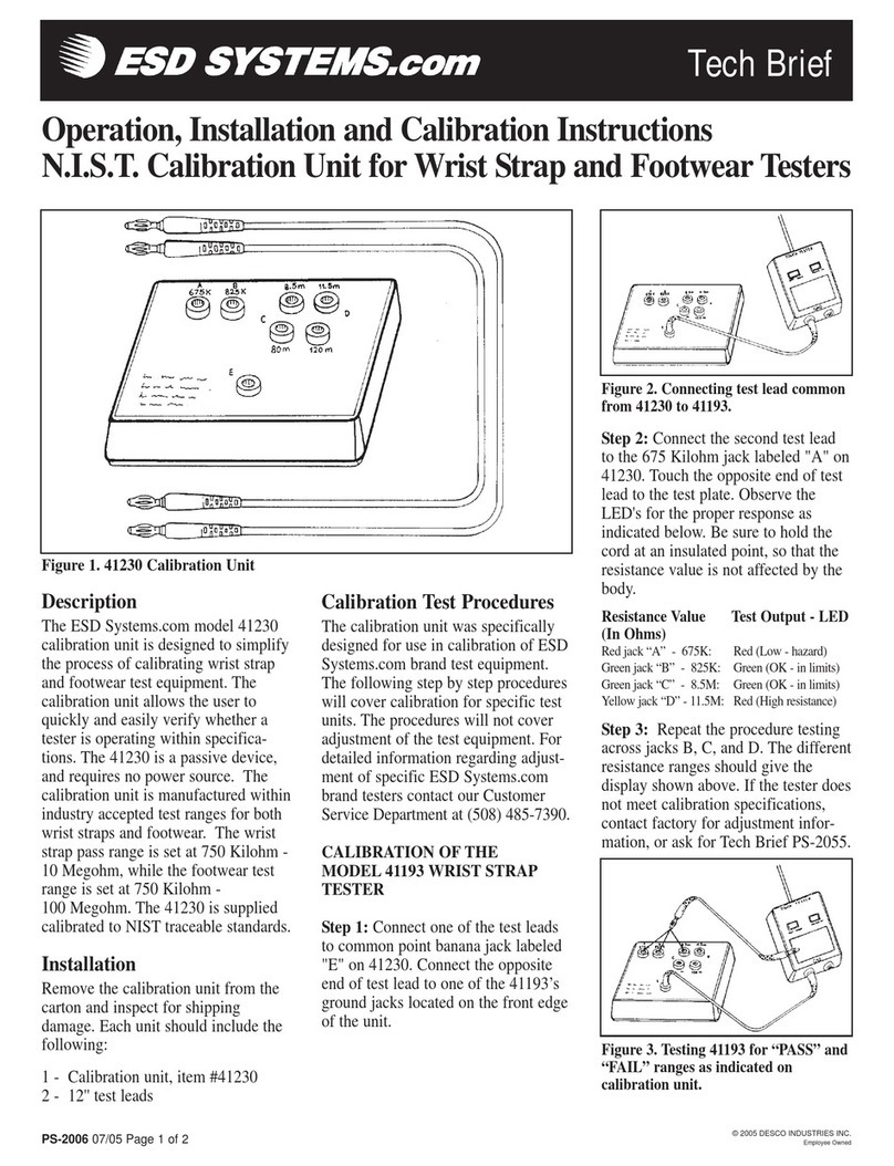
ESD SYSTEMS 41230 Use and care manual

ESD SYSTEMS

ESD SYSTEMS 41230 Use and care manual

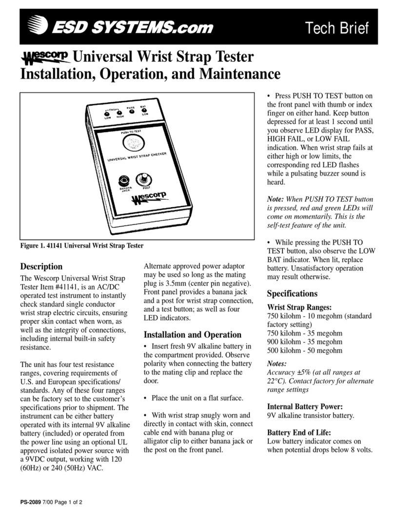
ESD SYSTEMS 41141 Installation and operating instructions

ESD SYSTEMS

ESD SYSTEMS 41141 Installation and operating instructions

ESD SYSTEMS 41290 Installation guide

ESD SYSTEMS

ESD SYSTEMS 41290 Installation guide

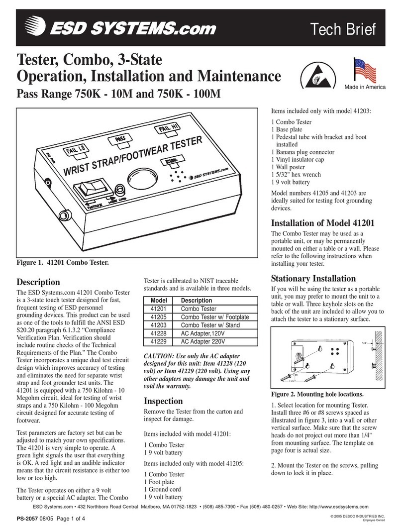
ESD SYSTEMS 41201 Instruction Manual

ESD SYSTEMS

ESD SYSTEMS 41201 Instruction Manual

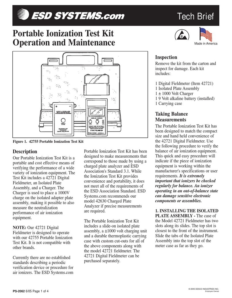
ESD SYSTEMS 42755 Installation guide

ESD SYSTEMS

ESD SYSTEMS 42755 Installation guide

Popular Test Equipment manuals by other brands

DMC MPT-250B Specification and operating instructions

DMC

DMC MPT-250B Specification and operating instructions

Inder Hydraulic P-231D User instruction manual

Inder

Inder Hydraulic P-231D User instruction manual

Tektronix 2440 Programmer's reference guide

Tektronix

Tektronix 2440 Programmer's reference guide

Ponovo PCT200 Series user manual

Ponovo

Ponovo PCT200 Series user manual

MRD Rail Technologies RelayDoc user manual

MRD Rail Technologies

MRD Rail Technologies RelayDoc user manual

AFL FlexScan FS200 OTDR Quick reference guide

AFL

AFL FlexScan FS200 OTDR Quick reference guide

Tektronix 7D11 instruction manual

Tektronix

Tektronix 7D11 instruction manual

Intact BTJ41 quick start guide

Intact

Intact BTJ41 quick start guide

Greenlee DVC-6 instruction manual

Greenlee

Greenlee DVC-6 instruction manual

Picotest PerfectPulse J2154 quick start guide

Picotest

Picotest PerfectPulse J2154 quick start guide

MULTI MEASURING INSTRUMENTS MIS-PV2 instruction manual

MULTI MEASURING INSTRUMENTS

MULTI MEASURING INSTRUMENTS MIS-PV2 instruction manual

Cirris 4200 Series user manual

Cirris

Cirris 4200 Series user manual

GW Instek GCP-1000 instruction manual

GW Instek

GW Instek GCP-1000 instruction manual

Elation C-LOADER II user guide

Elation

Elation C-LOADER II user guide

Dwyer Instruments UHH Installation and operating instructions

Dwyer Instruments

Dwyer Instruments UHH Installation and operating instructions

RS PRO IPT 1800 instruction manual

RS PRO

RS PRO IPT 1800 instruction manual

Fluke i1000s user manual

Fluke

Fluke i1000s user manual

Fluke CopperPro 990 quick start guide

Fluke

Fluke CopperPro 990 quick start guide

manuals.online logo
manuals.online logoBrands
  • About & Mission
  • Contact us
  • Privacy Policy
  • Terms and Conditions

Copyright 2025 Manuals.Online. All Rights Reserved.