URC B-292 User manual


AC-PRO®& AC-PRO-II®B-292 Secondary Injection Test Set Instruction Manual Rev 1.1
www.utilityrelay.com
Table of Contents
1.0 Introduction..........................................................................................................................1
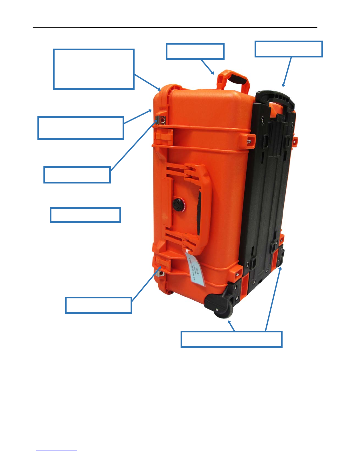
2.0 Overview..............................................................................................................................1
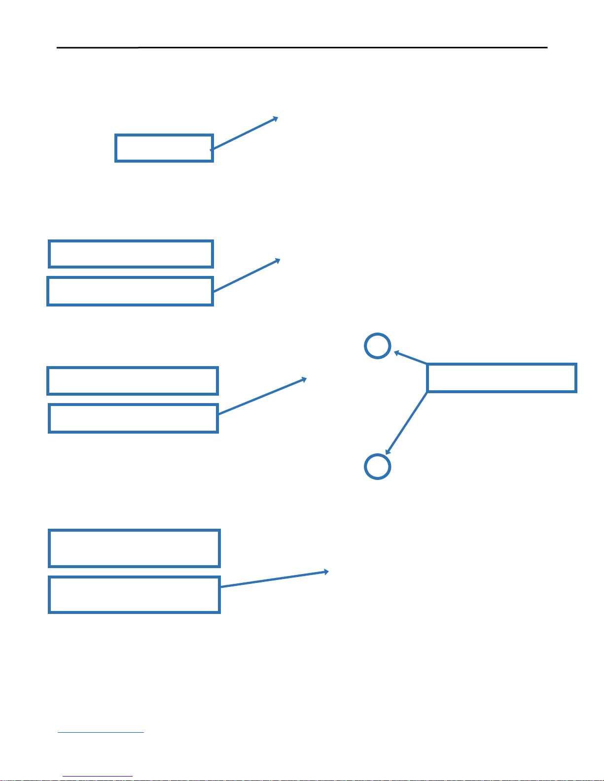
3.0 Test Set Controls..................................................................................................................6
3.1 Power...................................................................................................................6
3.2 Time Display .......................................................................................................6
3.3 Timer Clear Push Button .....................................................................................6
3.4 Start Push Button and LED.................................................................................. 6
3.5 Stop Push Button ................................................................................................. 6
3.6 Test Current display.............................................................................................6
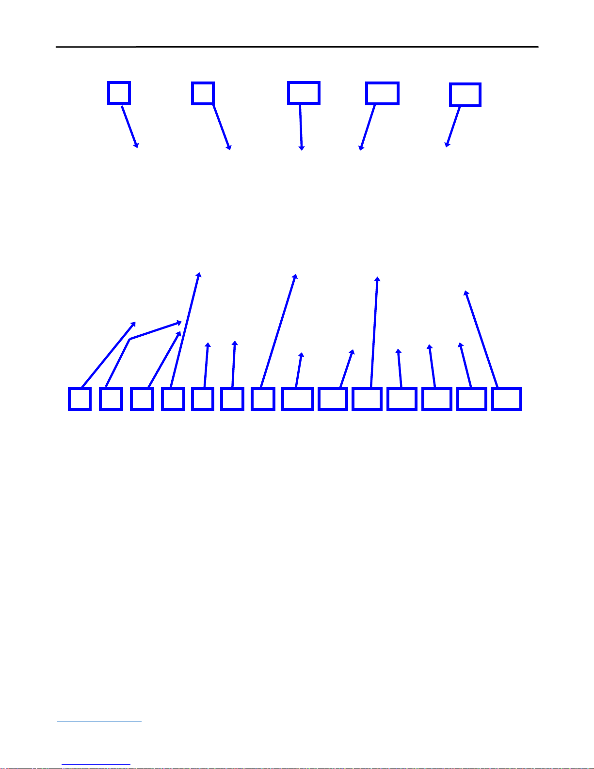
3.7 Current Preset Push Button..................................................................................7
3.8 Amp Coarse Adjust..............................................................................................7
3.9 Amp Fine Adjust..................................................................................................7
3.10 Phase Selector.................................................................................................... 7
3.11 Frequency Selector ............................................................................................7
3.12 Contrast Push Button.........................................................................................7
3.13 Ground Fault Type Selector Switch................................................................... 7
3.14 24V Fuse / Fuseholder....................................................................................... 7
4.0 Operation............................................................................................................................10
4.1 Connecting to AC-PRO or AC-PRO-II .............................................................10
4.1.1 AC-PRO-GR, Ground Return Trip Unit............................................... 10
4.2 Select the Frequency..........................................................................................10
4.3 Calculate Long Time (LT) Pick-Up Secondary Current.................................... 10
4.4 Long Time (LT) Pick-Up Test........................................................................... 11
4.5 Long Time (LT) Time Test................................................................................ 11
4.6 Calculate Short Time (ST) Pick-Up Secondary Current.................................... 12
4.7 Short Time (ST) Pick-Up Test...........................................................................12
4.8 Short Time (ST) Test.........................................................................................13
4.9 Calculate Instantaneous (I) Pick-Up Secondary Current...................................13
4.10 Instantaneous (I) Pick-Up Test ........................................................................14
4.11 Calculate Ground Fault (GF) Pick-Up Secondary Current.............................. 14
4.12 Ground Fault (GF) Pick-Up Test..................................................................... 15
4.13 Ground Fault (GF) Time Test.......................................................................... 15
4.14 AC-PRO Unbalance Testing............................................................................ 15
4.15 Calculate Neutral Overload (NOL) Pick-Up Secondary Current ....................16
4.16 Neutral Overload (NOL) Pick-Up Test............................................................16
4.17 Neutral Overload (NOL) Time Test ................................................................17
5.0 Quick-Trip®Testing........................................................................................................... 20
5.1 Calculate Quick-Trip Instantaneous (QT-I) Pick-Up Secondary Current..........20
5.2 Quick-Trip Instantaneous (QT-I) Pick-Up Test................................................. 20
5.3 Calculate Quick-Trip Ground Fault (QT-GF) Pick-Up Secondary Current ...... 21
5.4 Quick-Trip Ground Fault (QT-GF) Pick-Up Test .............................................21
6.0 Clearing Last Trip Data...................................................................................................... 22
7.0 Error/Fault Conditions .......................................................................................................22
7.1 Current Error......................................................................................................22
7.2 Thermal Limit.................................................................................................... 22
7.3 Unexpected GF Trip ..........................................................................................22
8.0 Specifications.....................................................................................................................22
For latest version, visit:
http://www.utilityrelay.com/Side_Bar/Instruction_Manuals.html

AC-PRO®& AC-PRO-II®B-292 Secondary Injection Test Set Instruction Manual Rev 1.1
www.utilityrelay.com
Figure 1: Test Set Exterior............................................................................................................ 2
Figure 2: Test Set Case Interior .................................................................................................... 3
Figure 3: Test Set Cables .............................................................................................................. 4
Figure 4: Control Panel Overview ................................................................................................5
Figure 5: AC-PRO Breaker Test Set Connections........................................................................8
Figure 6: AC-PRO-II Breaker Test Set Connections....................................................................9
Figure 7: AC-PRO Quick-Trip Testing Connections..................................................................18
Figure 8: AC-PRO-II Quick-Trip Testing Connections.............................................................. 19
Figure 9: AC-PRO Overload TCC..............................................................................................24
Figure 10: AC-PRO Unbalance TCC & Ground Fault TCC ......................................................25
Figure 11: AC-PRO Quick-Trip TCC.........................................................................................26
Figure 12: AC-PRO-II Overload TCC........................................................................................ 27
Figure 13: AC-PRO-II Ground Fault TCC .................................................................................28
Figure 14: AC-PRO-II Quick-Trip TCC.....................................................................................29
Figure 15: AC-PRO-II Neutral Overload TCC...........................................................................30
For latest version, visit:
http://www.utilityrelay.com/Side_Bar/Instruction_Manuals.html

AC-PRO®& AC-PRO-II®B-292 Secondary Injection Test Set Instruction Manual Rev 1.1
www.utilityrelay.com Page 1
1.0 Introduction
The Model B-292 Secondary Injection Test Set
is a single-phase test set specifically designed
for testing the operation of the AC-PRO and
AC-PRO-II microcontroller based trip units
manufactured by Utility Relay Company.
The earlier version test set with the “Red”
panel, can only be used to test the AC-PRO. It
cannot be used to test the AC-PRO-II.
The test set can test pick-up and time delays of
the various protection functions by driving
current into the trip unit on the secondary side
of the CT circuit.
The test set will test 60, 50, 40 or 25 Hertz
AC-PRO trip units. (The AC-PRO-II can be
set for either 50 Hertz or 60 Hertz).
The test set will test the AC-PRO or
AC-PRO-II trip system with the exception of
the CTs and associated wiring harness.
Important:
Secondary injection testing is not a
substitute for primary injection testing
that should be performed for any circuit
breaker retrofit.
2.0 Overview
The basic function of the test set is to deliver an
accurate level of AC current directly to the trip
unit under test and to verify the pick-up values
and times required for the AC-PRO or
AC-PRO-II to trip.
The technician running the test will operate the
Start (5), Stop (7), Clear (8) and Current Preset
(13) push buttons, adjust the Amp Coarse (14)
and Amp Fine (15) potentiometers (pots), and
adjust the Phase (11) and Frequency (16)
Selector switches. The two displays (6 & 12)
are used to indicate elapsed time in seconds and
test current in amps.
Note: Numbers in parentheses refer to the
labeled items in Figure 4.
Please reference the AC-PRO and
AC-PRO-II users manuals for complete
trip unit instructions.

AC-PRO®& AC-PRO-II®B-292 Secondary Injection Test Set Instruction Manual Rev 1.1
www.utilityrelay.com Page 2
Figure 1: Test Set Exterior
Copolymer Polypropylene
Compound
Chemical Resistant
Replaceable Steel-Axle Wheels
Padlock Provisions
Telescoping Handle
Large Handles
Rugged Construction for
protection during
operation, transport,
and shipping
Durable Latches

AC-PRO®& AC-PRO-II®B-292 Secondary Injection Test Set Instruction Manual Rev 1.1
www.utilityrelay.com Page 3
Figure 2: Test Set Case Interior
Interior Panel
Abbreviated
Instruction Manual
Long Time
Test Chart
Cable Storage

AC-PRO®& AC-PRO-II®B-292 Secondary Injection Test Set Instruction Manual Rev 1.1
www.utilityrelay.com Page 4
Figure 3: Test Set Cables
Power Cord
AC-PRO Test Set Harness
AC-PRO-II Test Set Harness
Labeled “For AC-PRO”
Labeled “For AC-PRO-II”
Note: different connector
AC-PRO Test Set Harness for
Breaker Test Port
Labeled “AC-PRO Test Set to
Breaker Test Port”

AC-PRO®& AC-PRO-II®B-292 Secondary Injection Test Set Instruction Manual Rev 1.1
www.utilityrelay.com Page 5
1Power Cable/Fuse Holder
Power cable connector with main fuse.
(120Vac 50/60Hz).
2Cooling Airflow Exhaust
Cooling air for the test set exits via this
filter opening (must not be blocked).
3Power ON/OFF Switch
4Start LED
Illuminates when test current
is flowing.
5Start Push Button
Starts test current flow and starts
the timer.
6Timer Display
Displays elapsed time of test current
flow in seconds.
7Stop Push Button
Stops test current flow and freezes
the timer.
8Clear Push Button
Resets the timer to zero.
9Contrast Push Button
Hold this button in until the desired
display contrast is reached.
10 Ground Fault Type Select Switch
Selects between Standard Residual GF
or Ground Return GF.
11 Phase Select Switch
Selects one of the phases (A,B,C) or
ground fault as the test current path.
12 Current Display
Displays measured true RMS current
and Current Preset value.
13 Current Preset Push Button
When held, the current display
indicates the setting of the Amp Coarse
and Fine pots but does not send current
to the trip unit.
14 Amp Coarse Pot
Used to make large adjustments
in current.
15 Amp Fine Pot
Used to make small adjustments
in current.
16 Frequency Select Switch
This switch selects the AC frequency;
25, 40, 50 or 60 Hertz for AC-PRO.
50 or 60 Hertz for AC-PRO-II.
17 Cooling Airflow Intake
Cooing air for the test set enters
via this filter opening (must not
be blocked).
18 AC-PRO or AC-PRO-II Test
Harness Connector
The trip unit connects to the test-set
with the supplied wire harness via
this connector.
19 24V Fuse / Fuseholder (fuse
is rated 1A/250V, 3AG slow
blow fuse)
Figure 4: Control Panel Overview
2
1
13
14
16
18
17
8
11
9
7
15
4
3
5
12
6
10
19

AC-PRO®& AC-PRO-II®B-292 Secondary Injection Test Set Instruction Manual Rev 1.1
www.utilityrelay.com Page 6
3.0 Test Set Controls
A brief description of the operation of the
various test set controls is given below.
The numbers in parentheses refer to the labels
in Figure 4.
3.1 Power
Power to the test set is controlled with the
Power On-Off switch.
An AC cord is supplied with the test set. The
recommended AC power source is 120V AC at
either 50 or 60 Hz. The 120 VAC receptacle
also contains the 5 Amp, 250V, 5 x 20mm main
power fuse.
3.2 Time Display
The test set will measure the time elapsed while
current is being delivered to the trip unit, and
display the time on the Timer display.
The displayed time is in seconds with 1/100 of
a second resolution.
The time will stop accumulating when a
trip occurs or when the Stop (7) push button
is pushed.
The timer display is cleared when the Clear (8)
push button is pushed.
3.3 Timer Clear Push Button
The Clear (8) push button clears the
Timer display.
3.4 Start Push Button and LED
The Start push button starts the test current
flow to the trip unit and simultaneously starts
the Timer (6).
The green LED located above the Start push
button indicates test current flow.
3.5 Stop Push Button
The Stop push button stops the test current flow
and simultaneously freezes the Timer (6).
3.6 Test Current display
The Test Current display indicates the true
RMS test current in amps, going to the
AC-PRO or AC-PRO-II during a test.
To determine the equivalent CT
primary current:
1-Amp AC-PRO or AC-PRO-II…multiply
the test set current by the CT Primary rating
set in the trip unit.
For example:
If the CT primary rating is 600 and the test
current is 1.50 amps, then the equivalent
primary current is:
1.50 x 600 = 900 amps primary
0.5 Amp Example…multiply the test set
current by the CT Ratio (CT Primary
Rating ÷ CT Secondary Rating).
For example:
If the CT Primary Rating is 600, the CT
Secondary Rating is 0.5A, and the test
current is 0.75 amps, then the equivalent
primary current is:
0.75 x (600 ÷0.5) = 900 amps
Note: If CT Secondary Rating is different than 1.0 or
0.5, use the 0.5 example above and replace 0.5 with
the specific CT secondary rating.
3
6
8
5
4
7
12

AC-PRO®& AC-PRO-II®B-292 Secondary Injection Test Set Instruction Manual Rev 1.1
www.utilityrelay.com Page 7
3.7 Current Preset Push Button
While the Current Preset push button is pushed,
the test set will display the current setting (from
the Amp Coarse and Fine adjust pots) in the
Current (12) display without actually driving
any current to the trip unit.
The sum of the Amp Coarse (14) and Fine (15)
pots is displayed in the Current (12) display
and is continually updated while the Current
Preset switch is pushed.
After the current pots are adjusted to the
desired test current as seen on the display,
release the Current Preset push button.
The test set limits the current set point level to
12.00 amps.
3.8 Amp Coarse Adjust
The Amps Coarse adjustment quickly changes
the test current to the trip unit or the test
Current Preset, with clockwise rotation
increasing the value.
3.9 Amp Fine Adjust
The Amps Fine adjustment slowly changes
the test current to the trip unit or the test
Current Preset, with clockwise rotation
increasing the value.
3.10 Phase Selector
The Phase Select selector switch is used to
select which phase of the trip unit the test
current is driven into. It selects between
Phase A, Phase B, Phase C or Ground
Fault (Neutral).
3.11 Frequency Selector
The Frequency selector switch is used to select
the AC test current frequency. This is used to
select either 25, 40, 50 or 60 Hz for AC-PRO.
The selections for AC-PRO-II are 50 or 60
Hertz.
3.12 Contrast Push Button
The Contrast push button changes the contrast
of both the Timer (6) and Current (12) displays.
The push button should be pushed until the
desired contrast is seen in the displays.
3.13 Ground Fault Type Selector Switch
The GF Type Selector switch selects between
the standard "residual" ground fault trip unit
and the special "ground return" ground fault
trip unit.
For AC-PRO, the option label on the front of
the AC-PRO indicates if that trip unit is the
special factory-configured "ground return"
type, with a “GR” suffix in the trip unit part
number.
For AC-PRO-II, Ground Fault Type is a user
setting. It can be set to Residual (standard) or
Ground Return.
Push the GF Type Selector switch so the
correct type of ground fault is selected.
Note: When the GF Type Switch is set to
standard “residual” and Phase switch is set to
A, B, or C, current is injected into the phase
current input and returned through the neutral
current input (to result in zero GF current).
When the GF Type switch is set to “ground
return” and Phase Switch is set to A, B, or C,
current is injected into the Phase input only.
3.14 24V Fuse / Fuseholder
The main 24V fuse is accessible from the front
panel. The fuse is rated 1A/250V max, type
3AG slow blow fuse.
13
14
15
11
9
10
16
19

AC-PRO®& AC-PRO-II®B-292 Secondary Injection Test Set Instruction Manual Rev 1.1
www.utilityrelay.com Page 8
A) AC-PRO Test Set Harness
B) Test Set Power Plug to AC-PRO
C) Test Set AC-PRO Harness Main
Connector
D) Test Set AC-PRO Harness Actuator
Connector
E) Circuit Breaker Wiring Harness
(previously connected to the AC-PRO)
Figure 5: AC-PRO Breaker Test Set Connections
C
E
D
AC-PRO®on breaker
B
A

AC-PRO®& AC-PRO-II®B-292 Secondary Injection Test Set Instruction Manual Rev 1.1
www.utilityrelay.com Page 9
F) AC-PRO-II Test Set Harness
G) Test Set Power Plug to AC-PRO-II
(Remove the cover (not pictured) to
gain access to the connector)
H) Test Set AC-PRO-II Harness Main
Connector (Remove the wire guard
(not pictured) to gain access to
the connector)
J) Test Set AC-PRO-II Harness
Actuator Connector
K) Circuit Breaker Wiring Harness
(previously connected to the
AC-PRO-II)
Figure 6: AC-PRO-II Breaker Test Set Connections
F
G
H
J
K
AC-PRO-IITM on breaker

AC-PRO®& AC-PRO-II®B-292 Secondary Injection Test Set Instruction Manual Rev 1.1
www.utilityrelay.com Page 10
4.0 Operation
The following describes the operation of the
test set. Note: Letters in parentheses refer to
the labeled items in Figure 5 and Figure 6.
4.1 Connecting to AC-PRO or AC-PRO-II
The B-292 Test Set includes two Test Harnesses,
one for AC-PRO and one for AC-PRO-II. The
Test Harness (A) or (F) makes the connections
from the test set to the trip unit (including power
(B or G)). It also provides a connector for
connection to the breaker harness (E) or (K) to
allow the AC-PRO or AC-PRO-II to fire the
breaker actuator and trip the breaker. See Figure
5 and Figure 6.
While the Power (3) switch is in the off
position (red LED in switch off):
1) Connect the round connector on the
Test Harness (A) or (F) to the connector
on the test set marked “AC-PRO or
AC-PRO-II” (18). Twist the outer
ring clockwise to fully seat and lock
the connector.
2) Remove the breaker wiring harness
from the “breaker harness” connector
on the trip unit (if installed on a
breaker). For AC-PRO-II remove the
wire guard (not pictured).
3) Connect the female ten-position
terminal block connector (C) or (H) on
the Test Harness to the trip unit.
4) AC-PRO: Connect the small round
connector on the Test Harness (B) to
the “24 VAC auxiliary power” jack.
AC-PRO-II: Connect the white
rectangular connector on the Test
Harness (G) to the “24VDC Aux
Power” input (after removing the
connector cover).
5) Connect the previously removed
breaker wiring harness connector to the
male ten-position terminal block on the
Test Harness Actuator Connector (D) or
(J) (if installed on a breaker).
6) Once all connections are made the test
set power can be turned on. The trip
unit should also power up.
4.1.1 AC-PRO-GR, Ground Return
Trip Unit
When testing a special AC-PRO trip unit with
"ground return" ground fault, or AC-PRO-II
with Ground Fault Type set to “Return”, see
Section 3.13.
4.2 Select the Frequency
Select the desired frequency of operation using
the Frequency (16) selector switch. This must
match the trip unit frequency.
4.3 Calculate Long Time (LT) Pick-Up
Secondary Current
Calculate the secondary LT pick-up current
(LTSPU) as follows:
For 1-Amp AC-PRO or AC-PRO-II:
LTSPU = LT Pick-Up
CT Primary Rating
Example: If the CT Primary rating is 1600 and
the LT pick-up is 800 amps, then
LTSPU = 800 = 0.50 amp
1600
Example: If the CT Primary rating is 1600 and
the LT pick-up is 1600 amps, then
LTSPU = 1600 = 1.00 amp
1600
For 0.5 Amp AC-PRO or AC-PRO-II:
LTSPU = LT Pick-Up X 0.5
CT Primary Rating
Example: If the CT Primary rating is 1600 and
the LT Pick-Up is 800 amps, then
LTSPU = 800 X 0.5 = 0.25 amp
1600

AC-PRO®& AC-PRO-II®B-292 Secondary Injection Test Set Instruction Manual Rev 1.1
www.utilityrelay.com Page 11
Example: If the CT Primary rating is 1600 and
the LT Pick-Up is 1600 amps, then
LTSPU = 1600 X 0.5 = 0.50 amp
1600
Note: If CT Secondary Rating is different than 1.0 or 0.5,
use the 0.5 example above and replace 0.5 with the
specific CT Secondary Rating.
Note: If Phase CT and Neutral CT do not have the same
Secondary Rating (i.e. if both not 1-Amp), temporarily
turn off Ground Fault Protection in the Trip Unit when
performing Long Time, Short Time, and Instantaneous
Tests.
4.4 Long Time (LT) Pick-Up Test
To test the LT pick-up:
1) Hold down the Current Preset (13)
while adjusting the Amp Coarse (14)
and Fine (15) pots until the Current (12)
display shows about 90% of the LT
pick-up current (LTSPU) previously
calculated.
2) Set the Phase selector (11) to either
Phase A, B or C.
3) Push the Start (5) button.
4) Increase the test current until the
display on the AC-PRO or AC-PRO-II
matches the programmed LT pick-up.
The red pick-up LED on the AC-PRO
or AC-PRO-II should be flickering or
solidly on. The test set current should
be within ±10% of LTSPU.
5) Push the Stop (7) button.
6) If desired, test the other two phases in
the same way.
4.5 Long Time (LT) Time Test
To test the LT time delay trip:
1) The first step is to select a test current.
For example, three times the LT pick-up
(3X on the TCC in Figure 9 or Figure
12). The desired test current is then 3 X
LTSPU.
Note, to accurately test the LT delay, the
test current must be at least 110% of the LT
pick-up.
2) Hold down the Current Preset (13)
while adjusting the Amp Coarse (14)
and Fine (15) pots until the Current (12)
display shows the test current calculated
in step 1. Release the Current Preset
(13) button.
3) Set the Phase selector (11) to either
Phase A, B or C.
4) Push the Clear (8) button to reset the
Timer (6) to zero.
5) Push the Start (5) button and quickly
make any minor adjustments required to
the Amp Fine (15) pot. The red pick-up
LED should be on. AC-PRO should
display “OVERLOAD”. AC-PRO-II
should display the current value.
6) When the trip unit trips, the test set
current will stop and the Timer (6) will
freeze and display the total trip time.
7) Compare the trip time with the TCC in
Figure 9 or Figure 12 for the LT time
band setting in the AC-PRO or
AC-PRO-II. The trip time can also be
verified against the LT Test Chart on
the inside panel of the test set case. The
LT Test Chart is also available at:
http://www.utilityrelay.com/PDFs/Prod
uct%20Manuals/AC-PRO_&_AC-
PRO-II_LT_Trip_Times.pdf
Verify that the trip unit saved the proper
last trip data.
8) Repeat for the other two phases if
desired.

AC-PRO®& AC-PRO-II®B-292 Secondary Injection Test Set Instruction Manual Rev 1.1
www.utilityrelay.com Page 12
4.6 Calculate Short Time (ST) Pick-Up
Secondary Current
Calculate the ST secondary pick-up current
(STSPU) as follows:
For 1-Amp AC-PRO or AC-PRO-II:
STSPU = ST Pick-Up
CT Primary Rating
Example: If the CT Primary rating is 1600 and
the ST pick-up is 6400 amps, then
STSPU = 6400 = 4.00 amp
1600
For 0.5 Amp AC-PRO or AC-PRO-II:
STSPU = ST Pick-Up X 0.5
CT Primary Rating
Example: If the CT Primary rating is 1600 and
the ST pick-up is 6400 amps, then
STSPU = 6400 X 0.5 = 2.00 amp
1600
Note: If CT Secondary Rating is different than 1.0 or 0.5,
use the 0.5 example above and replace 0.5 with the
specific CT Secondary Rating.
Note: If Phase CT and Neutral CT do not have the same
Secondary Rating (i.e. if both not 1-Amp), temporarily
turn off Ground Fault Protection in the Trip Unit when
performing Long Time, Short Time, and Instantaneous
Tests.
4.7 Short Time (ST) Pick-Up Test
To test the ST pick-up:
1) Hold down the Current Preset (13)
while adjusting the Amp Coarse (14)
and Fine (15) pots to 90% of the
calculated STSPU.
2) Set the Phase selector (11) to either
Phase A, B or C.
3) Push the Start (5) button but leave the
test current on only long enough to see
if a ST trip occurs. If the current is left
on long enough a LT trip will occur.
A ST trip should NOT occur.
4) Hold down the Current Preset (13)
while adjusting the Amp Coarse (14)
and Fine (15) pots to 110% of the
calculated STSPU.
5) Push the Clear (8) button to reset the
Timer (6) to zero.
6) Push the Start (5) button.
A ST trip should occur. The test set
current will stop and the Timer (6) will
freeze displaying the trip time.
7) Verify that the trip unit saved the proper
last trip data.
8) Repeat for the other two phases
if desired.

AC-PRO®& AC-PRO-II®B-292 Secondary Injection Test Set Instruction Manual Rev 1.1
www.utilityrelay.com Page 13
4.8 Short Time (ST) Test
To test the ST time delay trip:
1) The first step is to select a test current.
For example, 150% of the ST pick-up.
The desired test current is then 1.5 X
STSPU.
Note, to accurately test the ST delay, the
test current must be at least 110% of the ST
pick-up.
2) Hold down the Current Preset (13)
while adjusting the Amp Coarse (14)
and Fine (15) pots until the Current (12)
display shows the test current calculated
in step 1.
3) Set the Phase selector (11) to either
Phase A, B or C.
4) Push the Clear (8) button to reset the
Timer (6) to zero.
5) Push the Start (5) button.
6) When the AC-PRO or AC-PRO-II trips,
the test set current will stop and the
Timer (6) will freeze displaying the trip
time.
7) Compare the trip time with the TCC
in Figure 9 or Figure 12 for the ST
time band setting in the AC-PRO or
AC-PRO-II.
8) Verify that the trip unit saved the proper
last trip data.
9) Repeat for the other two phases if
desired.
4.9 Calculate Instantaneous (I) Pick-Up
Secondary Current
Calculate Instantaneous secondary pick-up
current (ISPU) as follows:
For 1-Amp AC-PRO or AC-PRO-II:
ISPU = I Pick-Up
CT Primary Rating
Example: If the CT Primary rating is 1600 and
Instantaneous pick-up is 9600 amps, then:
ISPU = 9600 = 6.00 amp
1600
For 0.5 Amp AC-PRO or AC-PRO-II:
ISPU = I Pick-Up X 0.5
CT Primary Rating
Example: If the CT Primary rating is 1600 and
Instantaneous pick-up is 9600 amps, then:
STSPU = 9600 X 0.5 = 3.00 amp
1600
Note: If CT Secondary Rating is different than 1.0 or 0.5,
use the 0.5 example above and replace 0.5 with the
specific CT Secondary Rating.
Note: If Phase CT and Neutral CT do not have the same
Secondary Rating (i.e. if both not 1-Amp), temporarily
turn off Ground Fault Protection in the Trip Unit when
performing Long Time, Short Time, and Instantaneous
Tests.

AC-PRO®& AC-PRO-II®B-292 Secondary Injection Test Set Instruction Manual Rev 1.1
www.utilityrelay.com Page 14
4.10 Instantaneous (I) Pick-Up Test
To test Instantaneous pick-up:
1) Hold down the Current Preset (13)
while adjusting the Amp Coarse (14)
and Fine (15) pots to 90% of the
calculated ISPU.
2) Set the Phase selector (11) to either
Phase A, B or C.
3) Push the Start (5) button but leave the
test current on only long enough to see
if an I trip occurs. If the current is left
on long enough a LT or ST trip will
occur. If ST is on, it is best to
temporarily turn it off.
An I trip should NOT occur.
4) Hold down the Current Preset (13)
while adjusting the Amp Coarse (14)
and Fine (15) pots to 110% of the
calculated ISPU.
5) Push the Clear (8) button to reset the
Timer (6) to zero.
6) Push the Start (5) button.
An I trip should occur. The test set
current will stop and the Timer (6) will
freeze displaying the trip time.
7) Verify that the AC-PRO or AC-PRO-II
saved the proper last trip data.
8) Repeat for the other two phases
if desired.
4.11 Calculate Ground Fault (GF) Pick-Up
Secondary Current
Calculate the GF secondary pick-up current
(GFSPU) as follows:
For 1-Amp AC-PRO or AC-PRO-II:
GFSPU = GF Pick-Up
CT Primary Rating
Example: If the CT Primary rating is 1600 and
the GF pick-up is 1200 amps, then:
GFSPU = 1200 = 0.75 amp
1600
For 0.5 Amp AC-PRO or AC-PRO-II:
GFSPU = GF Pick-Up X 0.5
CT Primary Rating
Example: If the CT Primary rating is 1600 and
the GF pick-up is 1200 amps, then:
GFSPU = 1200 X 0.5 = 0.38 amp
1600
Note: If the Neutral CT Secondary Rating is different
than 1.0 or 0.5, use the 0.5 example above and replace
0.5 with the specific Neutral CT Secondary Rating.

AC-PRO®& AC-PRO-II®B-292 Secondary Injection Test Set Instruction Manual Rev 1.1
www.utilityrelay.com Page 15
4.12 Ground Fault (GF) Pick-Up Test
Verify that the Ground Fault Type (10) selector
switch is in the correct position for the
AC-PRO or AC-PRO-II being tested.
To test the GF pick-up:
1) Set the Phase selector (11) switch
to GF.
2) Hold down the Current Preset (13)
while adjusting the Amp Coarse (14)
and Fine (15) pots to 90% of the
calculated GFSPU.
3) Push the Start (5) button but leave the
test current on only long enough to see
if a GF trip occurs.
A GF trip should NOT occur.
4) Hold down the Current Preset (13)
while adjusting the Amp Coarse (14)
and Fine (15) pots to 110% of the
calculated GFSPU.
5) Push the Clear (8) button to reset the
Timer (6) to zero.
6) Push the Start (5) button.
A GF trip should occur. The test set
current will stop and the Timer (6) will
freeze displaying the trip time.
7) Verify that the trip unit saved the proper
last trip data.
4.13 Ground Fault (GF) Time Test
To test the GF time delay trip:
1) The first step is to select a test current.
For example, 150% of the GF pick-up.
The desired test current is then 1.5 X
GFSPU.
Note, to accurately test the GF delay, the
test current must be at least 110% of the GF
pick-up.
2) Hold down the Current Preset (13)
while adjusting the Amp Coarse (14)
and Fine (15) pots until the Display (12)
shows the test current calculated in
step 1.
3) Set the Phase selector (11) to GF.
4) Push the Clear (8) button to reset the
timer (6) to zero.
5) Push the Start (5) button.
6) When the trip unit trips, the test set
current will stop and the Timer (6) will
freeze displaying the trip time.
7) Compare the trip time with the TCC in
Figure 10 or Figure 13 for the GF time
band and I2T settings in the AC-PRO
or AC-PRO-II.
8) Verify that the trip unit saved the proper
last trip data.
4.14 AC-PRO Unbalance Testing
The AC-PRO Unbalance function cannot be
tested with this test set.

AC-PRO®& AC-PRO-II®B-292 Secondary Injection Test Set Instruction Manual Rev 1.1
www.utilityrelay.com Page 16
4.15 Calculate Neutral Overload (NOL)
Pick-Up Secondary Current
Calculate the secondary NOL pick-up current
(NOLSPU) as follows:
For 1-Amp AC-PRO or AC-PRO-II:
NOLSPU = NOL Pick-Up
CT Primary Rating
Example: If the CT Primary rating is 1600 and
the NOL pick-up is 800 amps, then
NOLSPU = 800 = 0.50 amp
1600
Example: If the CT Primary rating is 1600 and
the NOL pick-up is 1600 amps, then
NOLSPU = 1600 = 1.00 amp
1600
For 0.5 Amp AC-PRO or AC-PRO-II:
NOLSPU = NOL Pick-Up X 0.5
CT Primary Rating
Example: If the CT Primary rating is 1600 and
the NOL Pick-Up is 800 amps, then
NOLSPU = 800 X 0.5 = 0.25 amp
1600
Example: If the CT Primary rating is 1600 and
the NOL Pick-Up is 1600 amps, then
NOLSPU = 1600 X 0.5 = 0.50 amp
1600
Note: If the Neutral CT Secondary Rating is different
than 1.0 or 0.5, use the 0.5 example above and replace
0.5 with the specific Neutral CT Secondary Rating.
4.16 Neutral Overload (NOL) Pick-Up Test
(AC-PRO-II only)
To test the NOL pick-up:
1) Temporarily turn Ground Fault
protection OFF in the trip unit.
2) Confirm the GF Switch (10) is in the
“Ground Return GF” position.
3) Confirm the Phase Select Switch (11) is
in the GF position.
4) Hold down the Current Preset (13)
while adjusting the Amp Coarse (14)
and Fine (15) pots until the Current (12)
display shows about 90% of the NOL
pick-up current (NOLSPU) previously
calculated.
5) Set the Phase selector (11) to GF.
6) Push the Start (5) button.
7) Increase the test current until the
display on the AC-PRO-II matches the
programmed NOL pick-up. The test set
current should be within ±10% of
NOLSPU.
8) Push the Stop (7) button.

AC-PRO®& AC-PRO-II®B-292 Secondary Injection Test Set Instruction Manual Rev 1.1
www.utilityrelay.com Page 17
4.17 Neutral Overload (NOL) Time Test
(AC-PRO-II only)
To test the NOL time delay trip:
1) The first step is to select a test current.
For example, three times the NOL pick-
up (3X on the TCC in Figure 15). The
desired test current is then 3 X NOLSPU.
Note, to accurately test the NOL delay, the
test current must be at least 110% of the
NOL pick-up.
2) Hold down the Current Preset (13)
while adjusting the Amp Coarse (14)
and Fine (15) pots until the Current (12)
display shows the test current calculated
in step 1. Release the Current Preset
(13) button.
3) The GF Switch (10) should still be in
the “Ground Return GF” position and
the Phase selector (11) should still be
set to GF.
4) Push the Clear (8) button to reset the
Timer (6) to zero.
5) Push the Start (5) button and quickly
make any minor adjustments required to
the Amp Fine (15) pot. The AC-PRO-II
should display the current value.
6) When the trip unit trips, the test set
current will stop and the Timer (6) will
freeze and display the total trip time.
7) Compare the trip time with the TCC in
Figure 15 for the NOL time band setting
in the AC-PRO-II.
8) Verify that the trip unit saved the proper
last trip data.
Table of contents
Other URC Test Equipment manuals
Popular Test Equipment manuals by other brands

LeCroy
LeCroy WaveRunner LT224 Quick reference guide

REVENTON
REVENTON INSPIRO BASIC Series Technical documentation

AGATE TECHNOLOGY
AGATE TECHNOLOGY AT-2040 Operator's manual

Agilent Technologies
Agilent Technologies Medalist x6000 installation guide

Sonel
Sonel VT-3 user manual

Macurco
Macurco CME1-FTG User instructions

Tektronix
Tektronix MDO3000 Series Technical reference

Alps Electric
Alps Electric SPEEDGLIDER Operator's manual

Siemens
Siemens PTS-4 Installation, operation & maintenance instructions

Oakton
Oakton CTS5 operating manual

DRUCK & TEMPERATUR Leitenberger
DRUCK & TEMPERATUR Leitenberger LR-Cal TLDMM operating manual

Ingun
Ingun VA 30 Series user manual