Danatronics ECHO Series User manual

Ver: 2.1A
User’s Guide
ECHO Series Thickness Gages

Danatronics, Corp.
2
Liability
Ultrasonic testing is a function of using the proper equipment (electronics, transducer,
cable and couplant combination) for the inspection and a qualified operator who knows
how to use this manual, the instruments and all calibration procedures. The improper use
of this equipment, along with the improper calibration can cause serious damage to
components, factories, facilities, personal injury, and even death. ALL DANATRONICS
ULTRASONIC THICKNESS GAGES ARE NOT INTRINSICALLY SAFE AND
SHOULD NOT BE USED IN ANY HAZEDOUS OR EXPLOSIVE AREAS.
It is understood that the operator of this equipment is a well trained inspector qualified by
either their own company or another outside agency to issue Ultrasonic Level I, 40 hour
class room training in Ultrasonic Theory. Danatronics, Corp. and any of its employees or
representatives shall not be held responsible for improper use of this equipment for its
intended use. Proper training, a complete understanding of Ultrasonic wave propagation,
thorough reading of this manual, proper transducer selection, correct zeroing of the
transducer, correct sound velocity, proper test blocks, proper cable length, proper
couplant selection all play a factor in successful ultrasonic thickness gaging. Special care
should be taken when test pieces have rough or painted surfaces, particularly those
applications where the test piece is thin to begin with as doubling of the echoes is
possible even if the transducer is capable of measuring the desired thickness. As
transducers wear or heat up, results can be either too thin due to a lack of sensitivity as a
result of wear or too thick due to heating up of the transducer, referred to as “drift.”

ECHO Series Ultrasonic Thickness Gages
3
Table of Contents
Liability .......................................................................................................................................... 2
1 Getting Started ........................................................................................................................... 6
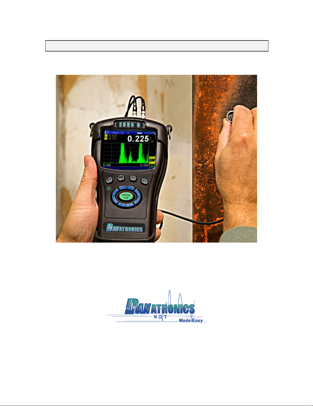
About the ECHO Series............................................................................................................ 6
Latest Software Updates.......................................................................................................... 6
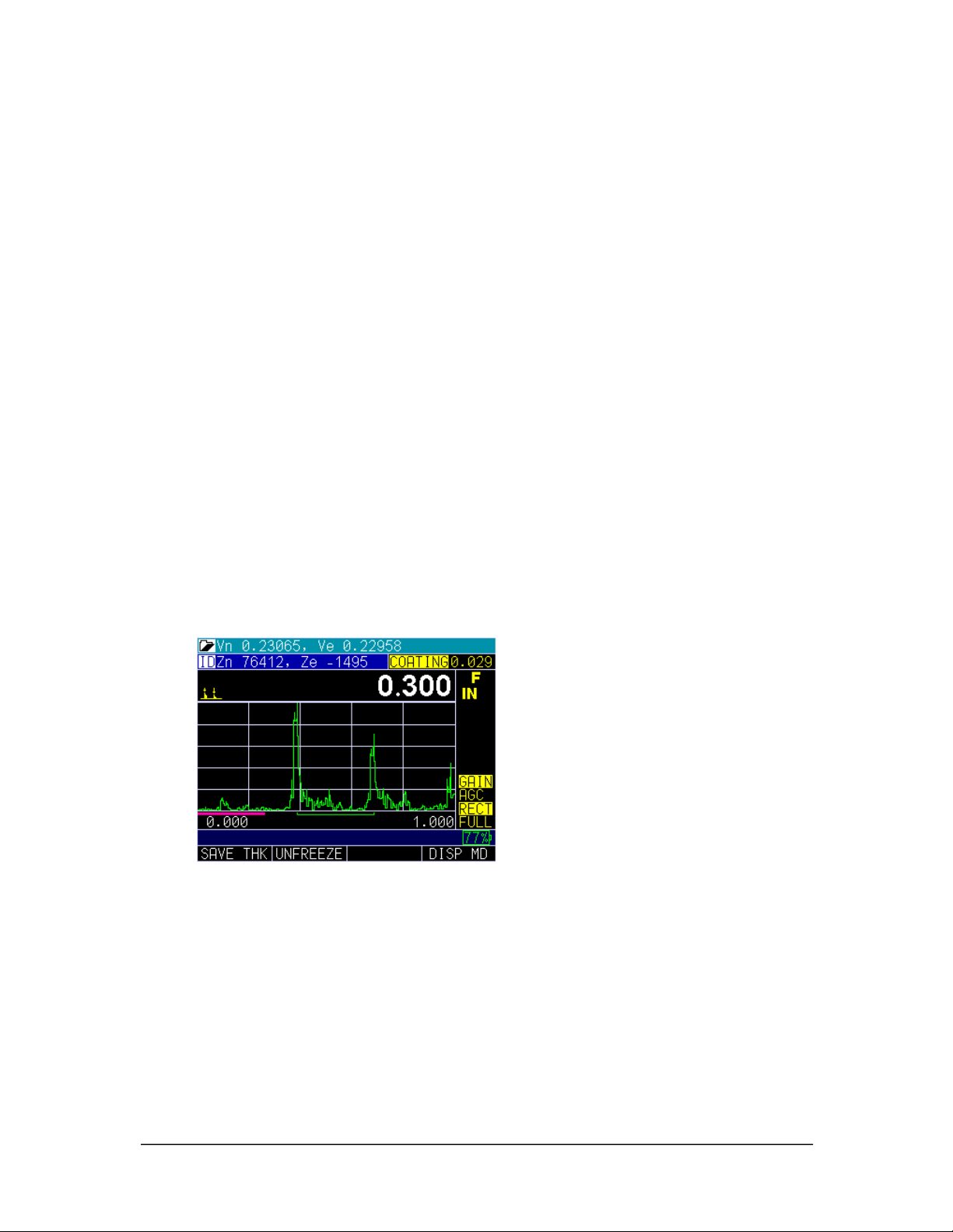
Coating Thickness.................................................................................................................. 7
Temperature Correction ......................................................................................................... 7
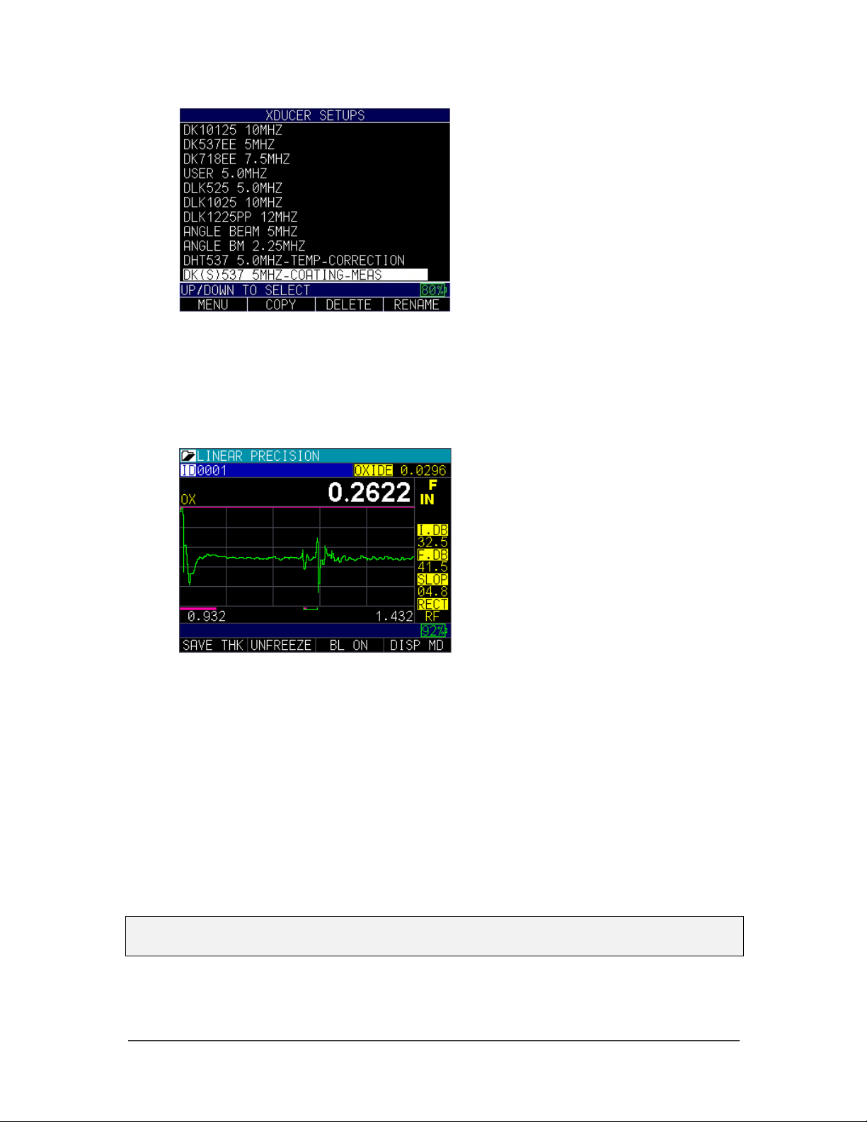
Stored Setups......................................................................................................................... 8
Oxide Scale.......................................................................................................................... 10
Setup Instructions .................................................................................................................. 11
Keypad Functions .................................................................................................................. 12
Function Keys......................................................................................................................... 13
Display Screen........................................................................................................................ 14
Battery Pack............................................................................................................................ 15
Monitoring the Battery Charge from the Display Screen...................................................... 15
Re-charging the Battery ....................................................................................................... 16
Using Non-rechargeable AA Batteries ................................................................................. 17
Boot, Bail, and Strap Features .............................................................................................. 18
Placing the Boot on the Gage .............................................................................................. 18
Removing the Boot from the Gage....................................................................................... 18
Using the Boot Strap and Bail .............................................................................................. 18
Other Gage Features .............................................................................................................. 18
Using the T/R 1 and T/R 2 Ports .......................................................................................... 18
Locating the USB Slot .......................................................................................................... 18
Using the Accessory Mount.................................................................................................. 18
Locating the Altitude Change Release Regulator ................................................................ 19
2 Using Basic Gage Operations ................................................................................................ 20
Power on the Gage ................................................................................................................. 20
Selecting the Menu Option .................................................................................................... 20
Performing a Reset................................................................................................................. 21
Database Reset.................................................................................................................... 22
Parameter Reset .................................................................................................................. 22
Database/Parameter Reset.................................................................................................. 23
About Screen .......................................................................................................................... 23
Backlight ................................................................................................................................. 24
3 Calibrating the Gage................................................................................................................ 25
Velocity Calibration Only ....................................................................................................... 25
Velocity and Zero Calibration................................................................................................ 26
Zero Calibration Only ............................................................................................................. 27
Delay Line Calibration............................................................................................................ 28
Automatic Zero ....................................................................................................................... 28
Measurement Mode with a Datalogger ................................................................................ 29
4 Customizing Display Options................................................................................................. 30
Backlight ................................................................................................................................. 30
Color ........................................................................................................................................ 30
User.......................................................................................................................................... 32
Waveform ................................................................................................................................ 32
Grid View ................................................................................................................................. 33
5 Adjusting the Initial Settings .................................................................................................. 36
About ....................................................................................................................................... 36
Auto Off ................................................................................................................................... 36
Clock........................................................................................................................................ 37
Language................................................................................................................................. 38

Danatronics, Corp.
4
General Lock........................................................................................................................... 38
Advanced Locks ..................................................................................................................... 39
Options .................................................................................................................................... 39
Reset........................................................................................................................................ 40
Resolution ............................................................................................................................... 40
Units......................................................................................................................................... 41
Beeper ..................................................................................................................................... 41
Vibrate ..................................................................................................................................... 42
6 Changing Measurement Options............................................................................................ 43
Alarm ....................................................................................................................................... 43
Vibrating Alarm Display........................................................................................................ 46
Blank........................................................................................................................................ 46
B-scan...................................................................................................................................... 47
Changing B-scan Max Thickness......................................................................................... 47
Saving an A-scan while in B-scan........................................................................................ 48
Differential (Diff) ..................................................................................................................... 49
Echo-to-Echo .......................................................................................................................... 50
Calibrating in Echo-to-Echo.................................................................................................. 52
Fast .......................................................................................................................................... 52
Gain.......................................................................................................................................... 53
Hold.......................................................................................................................................... 54
Measure Type.......................................................................................................................... 55
Range....................................................................................................................................... 56
Rect (Rectification)................................................................................................................. 56
Velocity.................................................................................................................................... 58
Transducer .............................................................................................................................. 59
7 Special Gage Functions .......................................................................................................... 60
Display Size Options .............................................................................................................. 60
Use of Blanks.......................................................................................................................... 60
Test .......................................................................................................................................... 60
Using the Save Option ........................................................................................................... 61
Choosing Where to Save the Readings................................................................................ 62
Using the Freeze Option ........................................................................................................ 63
Advanced Locks ..................................................................................................................... 64
8 Using the Datalogger Directory Mode.................................................................................... 67
Reviewing a File...................................................................................................................... 75
B-scan...................................................................................................................................... 76
9 Technical Specifications ......................................................................................................... 82
Product Specifications for the ECHO 9 Series .................................................................... 82
10 Software Options for the ECHO 9 Series............................................................................. 85
Datalogger with B-scan.......................................................................................................... 85
Saving a B-scan to Memory................................................................................................... 85
Encoded B-scan ..................................................................................................................... 85
Floating Gate........................................................................................................................... 86
Tracking gate .......................................................................................................................... 87
Peak Pitch Memory................................................................................................................. 89
Transducers ............................................................................................................................ 90
Acoustic Sound Speed for Common Materials ................................................................... 92
Updating the ECHO 9 Gage ................................................................................................... 94
Updating a Thickness Gage to be Compatible with Windows 8 or
Windows 10 USB .................................................................................................................... 95
Exporting Files from a Gage.................................................................................................. 96

ECHO Series Ultrasonic Thickness Gages
5
11 Additional ECHO Series Gage Information ......................................................................... 98
ECHO 7 and ECHO 8 Series................................................................................................... 98
Overview to Get Started....................................................................................................... 98
12 Technical Assistance .......................................................................................................... 101

Danatronics, Corp.
6
1 Getting Started
About the ECHO Series
The ECHO series are portable, digital, handheld ultrasonic thickness gages that are
specifically designed to measure the remaining wall thickness of primarily steel
structures.
ØVibralarm (vibrates gage below/above minimum/maximum thickness value)
ØIlluminating keypad for easy to view go-no-go thickness values
ØUnique, programmable left-hand/right-hand operation
ØUp to 20 hour battery life with rechargeable Li-Ion high capacity battery
ØSmall, easy to hold, ergonomic, custom molded, durable case with rubber keypad
designed for IP67 rating
ØMultiple dual and single element transducer options including high temperature
The ECHO 9 is a base gage in the color family offering a simple user interface packaged
in the same custom molded high-density plastic case with rubber keypad as the other
more sophisticated models. This gage offers reliable, accurate thickness readings on
mostly steel structures with access to only one side. The ECHO series can be easily
upgraded in the field to the add ECHO-9DL, EHCO-9CW, or ECHO-9DLW the live
color waveform (A-scan). We can even add our precision gage mode to allow for 0.0001"
resolution and higher frequency single element probes.
The ECHO-9W is a mid-range model consisting of the most commonly used features in a
thickness gage not requiring a datalogger, but with a live color A-scan. This model offers
gain adjustment, vibrating alarm and illuminating keypad conditions, and automated
transducer replacement notification feature. Like the ECHO 9, this model is field
upgradeable to include a datalogger with color waveform.
Our top of the line model, ECHO-9DLCW, contains all the same features of the ECHO 9
and ECHO-9CW and ECHO-9DL plus:
ØLive color waveform with gain, range, and rectify adjustments
Ø1M thickness reading Datalogger using a 32GB micro SD card memory is
essentially “unlimited”
ØThree pre-set files for linear, grid (row advance), grid (column advance), linear
plus custom point, 2D plus custom point, 3D, boiler, and sequential
ØB-scan
ØCustom rubber boot with built-in stand and 4-point chest harness
ØProbe Zero
Latest Software Updates
Danatronics periodically releases software updates with new and improved gage
functionality and features. You can download the latest standard software at no charge by
going to the ECHO section of www.danatronics.com and clicking on the support tab. Use

ECHO Series Ultrasonic Thickness Gages
7
the most recent version of Data XL, which is also available on the website to download at
no charge, and use the USB cable provided with the kit. Plug the cable into the USB port
on the top left of the ECHO and use the “Software Upgrade” tab to begin.
The following enhancements are included with the latest software for the ECHO 9 Series
(Version V1.15 or higher):
1. Coating Thickness
2. Temperature Correction
3. Stored Setups
4. Oxide Scale
Coating Thickness
For any ECHO 9 equipped with the live Waveform (A-scan), both the coating thickness
and substrate thickness can be displayed at the same time. When the Coating option is
enabled through the Menu options, the Measurements and the Calibration screen will be
turned on. ECHO will prompt you to calibrate the thickness of the substrate first (without
the coating), and preform your normal 2-point calibration (described later in this manual).
Next, you must perform Cal Zero on the thin section and Cal Vel on the thick section
followed by pressing the OK button. ECHO will then prompt you to put on a coating of
the known thickness and press the F3 Vel key to adjust the coating thickness displayed in
yellow in the top right hand corner of the screen (shown in the image below). ECHO
calculates the sound speed of the coating and substrate independently. There is no need
for special dual transducers.
Temperature Correction
The Temperature Correction feature allows you to enter the calibrated temperature,
current temperature, and coefficient factor, which corrects for sound speed variations
between the calibrated temperature and current temperature.

Danatronics, Corp.
8
Stored Setups
You can store and re-call up to 2,700 unique applications setups with this updated
feature, allowing for easy parameter recall for a more efficient inspection. ECHO keeps
track of various parameters, such as Gain, Range, Rectification, and Alarm Values. To
get started, follow the steps below.
1. Choose the transducer you are using and perform your normal test.
F1 F2 F3
2. If you alter a setup parameter, such as Gain, Range, Blank, or Rectification, then
you will see in the main Menu screen as shown below:
3. After scrolling to the Xducer Setups option, press the MENU/OK key. An
asterisk next to the transducer file you started with.

ECHO Series Ultrasonic Thickness Gages
9
4. At this point, you can either SAVE the file by pressing the F2 key or DISCARD
it by pressing the F3 key. If you press the F2 key to save the file, then a screen
will appear with an alphanumeric keypad so you can name the custom file.
5. After naming the file, press the F4 – Done key. The new custom setup file will
populate at the end of the transducer list.
When the new file is highlighted in the transducer list, you can press the
MENU/OK key to use the custom setup or press the F3 – DELETE key to the
delete it. You can also press the F4 – RENAME key to modify the file name.
Note: Default transducers in the initial library cannot be deleted.
6. You may have more than one custom setup, as shown in the example below:

Danatronics, Corp.
10
Oxide Scale
The Oxide Scale option comes standard on the ECHO-7W and ECHO-7DLW.
When equipped with the Oxide Scale option and a 20mhz delay line transducer, both
ECHO 7 and ECHO 8 units with live waveform can measure the Oxide Scale (0.015" –
0.040") and tube thickness calibrated to their independent sound speeds.
To use the Oxide Scale option, begin at the main Menu and go to the Setups option.
Select DEF S3, DLK2025-OXIDE, or DLK20125. Use samples of known tube thickness
and known oxide thickness to perform a calibration.
Press the MENU/OK key. Select the Calibration option followed by the MENU/OK
key. The following prompt will appear:
Use screen above
Follow the prompts by pressing the F2 key to calibrate the tube thickness first (Cal Zero
on the thin section, and Cal Vel on the thick section). Press the MENU/OK key. Next,
press the F3 –VEL key to calibrate while coupled to a sample with a known oxide scale
thickness.
Note: You may need to increase I.DB or F.DB to get an echo image similar to the one
shown below.

ECHO Series Ultrasonic Thickness Gages
11
Setup Instructions
When turning on the ECHO 9 series, the gage does an automatic zeroing of the
transducer thus eliminating the need for an on-block zero. (This manual is
interchangeable when using the ECHO series basic operations and calibration steps, with
the exception of the datalogger, B-scan, and Echo-to-Echo features.) The ECHO 9 will
electronically zero the transducer upon power up and at a particular time during normal
operation to ensure the transducer is working in accordance with electronic zeroing
procedures. This feature is particularly important on high temperature materials and when
the transducer becomes worn.
Important Notice: Please make sure the transducer is NOT coupled to the test piece
when the gage is first turned on and that there is no couplant on the end of the
transducer. The transducer should also be at room temperature and clean without any
noticeable wear.
For a more accurate “span” of calibration, Danatronics recommends a zero calibration
and sound velocity calibration as well.
When you press and hold the F1 key, the gage will power on. Find the transducer part
number (located on the back of the transducer) and match it to the same number on the
gage display screen. Here is what the first screen will look like (see reset and backlight
sections for additional details):

Danatronics, Corp.
12
Once you select the transducer number, press the MENU/OK key on the gage. Be sure to
wipe off any couplant from the transducer face. At this point, the gage will preform an
automatic probe zero.
Note: If you get an “insert transducer” message you can try swapping the connector or
rotating the molded plug from where the cable plugs into the top of the gage. If this does
not work, the transducer likely needs to be replaced.
Keypad Functions
The figure below shows the full keypad layout representative of each ECHO series
thickness gage.
The following table refers to each key or symbol shown on the keypad. Note the F keys
correspond to text above each key and prompts change depending on which screen you
are adjusting.
Key
Function
Up arrow key
Down arrow key
Left arrow key
Right arrow key
On/Off symbol (under the F1 key)

ECHO Series Ultrasonic Thickness Gages
13
MENU/OK key
F1
Varies
F2
Varies
F3
Varies
F4
Varies
Function Keys
Function keys, or F keys (e.g., F1, F2, F3, F4), have various gage functions and may
change depending on the display screen. View the bottom of the display screen for the
function that corresponds with the appropriate F key. For example, F1 may correspond
with the Save function, F2 with the Freeze function, or F3 with the Directory function
(Dir). Many times the left or right arrow keys can be used instead of the MENU/OK key
to highlight a parameter or to see what is under the selected choice.

Danatronics, Corp.
14
Display Screen
The gage has a graphic style color display with 320 x 240 (1/4 VGA) pixel density.
Viewing the screen is best from straight above or slightly below the surface rather than
from side to side. If external temperatures are below 32°F (0°C), the display may be
slower to update information.
Color thickness reading only on ECHO 9
Color Waveform in Echo-to-Echo mode, filename, ID, thickness value,
gain, rectification, battery life, alarm, freeze, backlight, and display mode.
Transducer screen, menu, reset, backlight
F1 F2 F3

ECHO Series Ultrasonic Thickness Gages
15
The top part of the display screen shows the File Name, ID Number, AA, and 0001 for
grid column and row. The lower part of the display acts as an interactive tool that allows
you to decide how you want to proceed with the information that is displayed on the
screen. The middle part of the screen shows the following: thickness value; In, mm or
usec; Echo-to-Echo symbol; LOS (loss of signal); Freeze; Fast Min or Max; Alarm
indicator; Differential mode; Low, Med or High gain; and percent remaining battery life.
Battery Pack
To ensure the highest level of performance and protection, the battery compartment is
separated from the electronic components of the gage.
Monitoring the Battery Charge from the Display Screen
The ECHO series continuously displays the percentage of battery life remaining on the
bottom right corner of the measurement display screen. When the battery life is below
10%, the battery indicator will turn from green to red. When the battery life is below 5%,
the indicator will flash.
Note: Power off the ECHO series gage to ensure any saved data is stored internally.
F1 F2 F3 F4

Danatronics, Corp.
16
Re-charging the Battery
To re-charge the battery, simply plug in the charger to an AC outlet (between 100-240V)
and plug the other end into the USB connector on the top of ECHO series gage. The F4
key will light up with a blue LED when charging, and the light will go out when fully
charged. Allow several hours (up to 10 hours) to fully charge.
Note: There is a battery indication monitor on the bottom right of the screen showing the
percent of battery life, as seen below at 75%.
USB port

ECHO Series Ultrasonic Thickness Gages
17
You may also use a computer instead of the wall charger to charge the gage, but this will
take significantly more time than using an AC outlet. If you decide to charge the gage
using this method, make sure the gage is powered off before you connect the USB to the
computer and to the gage itself.
When charging is complete, the F4 key will appear translucent in color. Power off the
gage, and unplug the charger from the USB connector on the top of the gage.
Using Non-rechargeable AA Batteries
A non-rechargeable alkaline AA pack is also available. This option requires a spare tray
and 3 AA batteries. Follow these steps to insert non-rechargeable batteries:
1. Un-screw the battery door.
2. Disconnect the Li-Ion battery connector.
3. Plug in the AA tray connector.
4. Replace the battery door and tighten screws.
Note: When using the 3 AA battery tray, batteries cannot be re-charged.

Danatronics, Corp.
18
Boot, Bail, and Strap Features
The custom rubber boot with built in bail and 4-point chest harness is an accessory for the
ECHO series gages. Not only does the boot help to protect the gage from the elements,
but the functional bail and strap also offers a variety of positioning options.
Placing the Boot on the Gage
To insert the gage into the rubber boot, follow these steps:
1. Guide the gage strap through the hole at the top of the boot (either right or left
side).
2. Slide the gage into the top of the boot.
3. Gently apply pressure to the bottom of the gage until it fully pops into the boot.
Removing the Boot from the Gage
Be sure that the bail is set in the open position before attempting to remove the boot.
Follow these steps:
1. Apply pressure to the bottom two corners of the boot until the gage pops out.
2. Wriggle the top section of the gage out of the boot.
3. Guide the gage strap through the hole at the top of the boot.
Using the Boot Strap and Bail
The boot strap is attached to the bail on the back of the boot. It can be used as a right- or
left-handed strap, or a finger strap. You can also connect the strap to a 4-point chest
harness for hands-free use.
The bail, including the straps, can be removed from the boot. This is useful when adding
accessories or locating the gage’s serial number. Simply open the bail and apply gentle
pressure to one side of the connector, which is located at the top of the bail. The piece
will pop off exposing the accessory mount (see below) and gage serial number.
Other Gage Features
Using the T/R 1 and T/R 2 Ports
On the top of the ECHO series gages are two ports for transducer connectivity.
If you are using a dual element transducer, you may use either port—T/R 1 or T/R 2—
interchangeably. However, if you are using a single element transducer, plug the
connector into the T/R 1 port only.
Locating the USB Slot
The ECHO series gages are furnished with a USB 2.0 slot on the top of the gage. Use the
USB slot to connect AC chargers or to connect to a computer for cross-functionality.
Using the Accessory Mount
On the back of the gage is a ¼x 20 accessory mount. This connector point is compatible
with a multitude of accessories including a magnetic pipe attachment and a Gorilla Pod.

ECHO Series Ultrasonic Thickness Gages
19
Locating the Altitude Change Release Regulator
At the bottom of the gage is a circular outline with small holes. This feature regulates
pressure due to altitude change. Any pressure built up inside the gage will be
automatically released.

Danatronics, Corp.
20
2 Using Basic Gage Operations
Power on the Gage
To power on any of the ECHO series thickness gages, follow these steps:
1. Press and hold the F1 key for more than 3 seconds. The power symbol, as shown
below, is under the F1 key printed on the keypad.
2. The following screen will appear on the gage display:
For the purposes of this manual, we will refer to this screen as the Home screen.
3. Use the up and down arrow keys to select a transducer and press the MENU/OK
key. (Please note, the transducer selection will automatically display the last used
transducer prior to shut off.)
From the Home screen the following F keys are available:
•F1 – Menu
•F2 – Reset
•F3 – Bklite
Selecting the Menu Option
The gage offers several Menu options as shown below:
Power symbol
under the F1 key
Other manuals for ECHO Series
2
This manual suits for next models
7
Table of contents
Popular Test Equipment manuals by other brands

Konig
Konig CMP-RCT31 manual

Tempo Fitness
Tempo Fitness 24A STATION MASTER PRO instruction manual

BEAMEX
BEAMEX PO8C user guide

Psiber
Psiber CableMaster 600 quick start guide

BACtrack
BACtrack BREATH ALCOHOL DETECTOR owner's manual

Industrial Scientific
Industrial Scientific DS2 Docking Station Administrator's guide