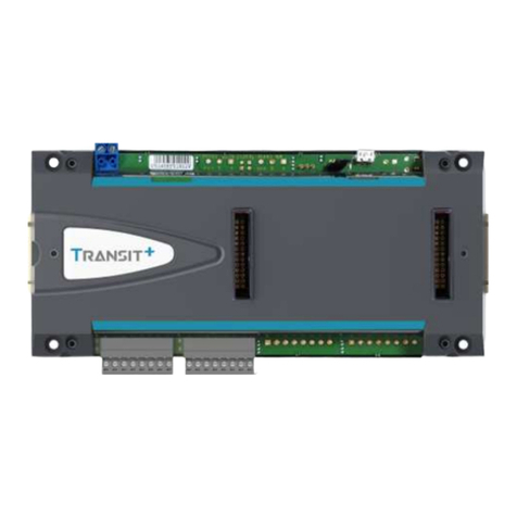
urmet domus 1083 User manual

DS 1083-015A LBT 8483
Mod.
1083
DISPOSITIVO PER TELECAMERE DI CONTROLLO
CONTROL CAMERAS DEVICE
DISPOSITIF POUR CAMÉRAS DE SOURVEILLANCE
DISPOSITIVO PARA CÁMARAS DE CONTROL
GERÄT FÜR KONTROLLKAMERAS
Sch./Ref. 1083/69

2DS1083-015A 3
DS1083-015A
ITALIANO ENGLISH
DESCRIZIONE
Il dispositivo Sch.1083/69 consente di commutare il segnale video coassiale o differenziale e l’alimentazione
di massimo 4 unità di ripresa.
CARATTERISTICHE ELETTRICHE
Tensione alimentazione (+V, 0V): .............................................................................................. 18 Vcc ± 20%
Assorbimento max: ...............................................................................................................................50 mA
Tensione alimentazione (+12, 0V):...............................................12 Vcc ± 10% (assorbimento max 50 mA)
Tensione alimentazione (R2, 0V): ......................................................12 Vcc ± 10% (assorbimento max 2A)
Temperatura di funzionamento: ..................................................................................................... -5÷+50 °C
Umidità: ................................................................................................................................ 90% UR @ 30 °C
Massima distanza tra contatti tasto e morsetti (RES) ............................................................................. 300m
DESCRIZIONE MORSETTI
RE; 0V ingresso attivazione della telecamera 1 riferito a 0V
RF; 0V ingresso attivazione della telecamera 2 riferito a 0V
RG; 0V ingresso attivazione della telecamera 3 riferito a 0V
RH; 0V ingresso attivazione della telecamera 4 riferito a 0V
R2; 0V ingresso alimentazione per telecamere
+V; 0V ingresso alimentazione commutatore video 18Vcc
+12; 0V ingresso alimentazione commutatore video 12Vcc
AU; BU uscita segnale video verso il monitor con collegamento differenziale
AU; V5 uscita segnale video verso il monitor con collegamento coassiale
A5; B5 ingresso segnale video differenziale passante su uscita
A5; V5 ingresso segnale video coassiale passante su uscita
RES; 0V ingresso per resettare la commutazione tra le diverse telecamere riferito a 0V (in questo caso
togliere il ponticello tra i morsetti RES e 0V)
T; 0V ingresso per l’attivazione ciclica delle telecamere riferito a 0V (in questo caso togliere il ponticello
tra i morsetti RES e 0V)
A1; B1 ingresso segnale video differenziale telecamera 1
A2; B2 ingresso segnale video differenziale telecamera 2
A3; B3 ingresso segnale video differenziale telecamera 3
A4; B3 ingresso segnale video differenziale telecamera 4
A1; V5 ingresso segnale video coassiale telecamera 1
A2; V5 ingresso segnale video coassiale telecamera 2
A3; V5 ingresso segnale video coassiale telecamera 3
A4; V5 ingresso segnale video coassiale telecamera 4
TC1; V5 uscita alimentazione per telecamera 1
TC2; V5 uscita alimentazione per telecamera 2
TC3; V5 uscita alimentazione per telecamera 3
TC4; V5 uscita alimentazione per telecamera 4
DESCRIPTION
The device Ref. 1083/69 allows to switch the coaxial or differential video signal and the power supply of 4
cameras max.
ELECTRICAL SPECIFICATIONS
Power voltage (+V, 0V): .............................................................................................................18 Vdc ± 20%
Max. current consumption: ...................................................................................................................50 mA
Power supply voltage (+12, 0V): .......................................................... 12 Vdc ± 10% (max. current 50 mA)
Power supply voltage (R2, 0V): ...................................................... ............12 Vdc ± 10% (max. current 2A)
Working temperature range: ............................................................................................... from -5 to +50 °C
Humidity: .............................................................................................................................. 90% UR @ 30 °C
Maximum distance between button contacts and terminals (RES) ........................................................ 300m
TERMINAL PINS DESCRIPTION
RE; 0V input for camera 1 activation referred to 0V
RF; 0V input for camera 2 activation referred to 0V
RG; 0V input for camera 3 activation referred to 0V
RH; 0V input for camera 4 activation referred to 0V
R2; 0V power supply input for cameras
+V; 0V power supply input for video switching 18Vdc
+12; 0V power supply input for video switching 12Vdc
AU; BU video signal output for the monitor with differential connection
AU; V5 video signal output for the monitor with coaxial connection
A5; B5 differential video signal input, pass through
A5; V5 coaxial video signal input, pass through
RES; 0V input used to reset the switch position among cameras, referred to 0V (in this case, remove the
jumper between the terminal pins RES and 0V)
T; 0V input for cameras cyclic activation, referred to 0V (in this case, remove the jumper between the
terminal pins RES and 0V)
A1; B1 differential video signal input for camera 1
A2; B2 differential video signal input for camera 2
A3; B3 differential video signal input for camera 3
A4; B3 differential video signal input for camera 4
A1; V5 coaxial video signal input for camera 1
A2; V5 coaxial video signal input for camera 2
A3; V5 coaxial video signal input for camera 3
A4; V5 coaxial video signal input for camera 4
TC1; V5 power supply output for camera 1
TC2; V5 power supply output for camera 2
TC3; V5 power supply output for camera 3
TC4; V5 power supply output for camera 4

4DS1083-015A 5
DS1083-015A
FRANÇAIS
DESCRIPTION
Le dispositif Réf. 1083/69 permet de commuter le signal vidéo coaxial ou différentiel et l’alimentation de 4
caméras au maximum.
CARACTÉRISTIQUES TECHNIQUES
Power voltage (+V, 0V): ............................................................................................................. 18 Vcc ± 20%
Consommation maximale: .....................................................................................................................50 mA
Tension d’alimentation (+12, 0V): ........................................................12 Vcc ± 10% (courant max. 50 mA)
Tension d’alimentation (R2, 0V): ................................................................ 12 Vcc ± 10% (courant max. 2A)
Température de fonctionnement: ................................................................................................... -5÷+50 °C
Humidité: ............................................................................................................................. 90% H.R. à 30 °C
Distance maximum entre les contacts touche et bornes (RES) ............................................................. 300m
DESCRIPTIONS DES BORNES
RE; 0V entrée activation de la caméra 1 reliée à un potentiel de référence de 0V
RF; 0V entrée activation de la caméra 2 reliée à un potentiel de référence de 0V
RG; 0V entrée activation de la caméra 3 reliée à un potentiel de référence de 0V
RH; 0V entrée activation de la caméra 4 reliée à un potentiel de référence de 0V
R2; 0V entrée alimentation pour caméras
+V; 0V entrée alimentation pour commutateur vidéo 18 Vcc
+12; 0V entrée alimentation pour commutateur vidéo 12Vcc
AU; BU sortie signal vidéo pour le moniteur avec connexion différentielle
AU; V5 sortie signal vidéo pour le moniteur avec connexion coaxiale
A5; B5 entrée signal vidéo différentiel passant sur sortie
A5; V5 entrée signal vidéo coaxial passant sur sortie
RES; 0V entrée pour remettre le commutateur des différentes caméras à la position initiale; cette entrée est
reliée à un potentiel de référence de 0V (dans ce cas, enlever le pontet entre les bornes RES et
0V)
T; 0V entrée pour l’activation cyclique des caméras reliée à un potentiel de référence de 0V (dans ce
cas, enlever le pontet entre les bornes RES et 0V)
A1; B1 entrée signal vidéo différentiel pour caméra 1
A2; B2 entrée signal vidéo différentiel pour caméra 2
A3; B3 entrée signal vidéo différentiel pour caméra 3
A4; B3 entrée signal vidéo différentiel pour caméra 4
A1; V5 entrée signal vidéo coaxial pour caméra 1
A2; V5 entrée signal vidéo coaxial pour caméra 2
A3; V5 entrée signal vidéo coaxial pour caméra 3
A4; V5 entrée signal vidéo coaxial pour caméra 4
TC1; V5 sortie alimentation pour caméra 1
TC2; V5 sortie alimentation pour caméra 2
TC3; V5 sortie alimentation pour caméra 3
TC4; V5 sortie alimentation pour caméra 4
ESPAÑOL
DESCRIPCIÓN
El dispositivo Ref.1083/69 permite de conmutar el señal vidéo coaxial o diferencial y la alimentación de
máximo 4 cámaras.
CARACTERÍSTICAS ELÉCTRICAS
Tensión de alimentación (+V, 0V):............................................................................................. 18 Vcc ± 20%
Absorción máx: .....................................................................................................................................50 mA
Tensión de alimentación (+12, 0V): ............................................... ...12 Vcc ± 10% (absorción máx 50 mA)
Tensión de alimentación (R2, 0V): .......................................................... 12 Vcc ± 10% (absorción máx 2A)
Temperatura de funcionamiento: ................................................................................................... -5÷+50 °C
Humedad:............................................................................................................................. 90% UR @ 30 °C
Máxima distancia entre contactos tecla y bornes (RES) ........................................................................ 300m
DESCRIPCIÓN BORNES
RE; 0V Entrada activación de la cámara 1 referido a 0V
RF; 0V Entrada activación de la cámara 2 referido a 0V
RG; 0V Entrada activación de la cámara 3 referido a 0V
RH; 0V Entrada activación de la cámara 4 referido a 0V
R2; 0V entrada alimentación para cámara
+V; 0V entrada alimentación conmutador vidéo 18Vcc
+12; 0V entrada alimentación conmutador vidéo 12Vcc
AU; BU salida señal vidéo hacia el monitor con conexión diferencial
AU; V5 salida señal vidéo hacia el monitor con conexión coaxial
A5; B5 entrada señal vidéo diferencial en tránsito sobre la salida
A5; V5 entrada señal vidéo coaxial en tránsito sobre la salida
RES; 0V entrada para restablecer la conmutación entre las diferentes cámaras referido a 0V (en este caso
quitar el puente de conexiones entre los bornes RES y 0V)
T; 0V entrada para la activación cíclica de las cámaras referido a 0V (en este caso quitar el puente de
conexiones entre los bornes RES y 0V)
A1; B1 entrada señal vidéo diferencial cámara 1
A2; B2 entrada señal vidéo diferencial cámara 2
A3; B3 entrada señal vidéo diferencial cámara 3
A4; B3 entrada señal vidéo diferencial cámara 4
A1; V5 entrada señal vidéo coaxial cámara 1
A2; V5 entrada señal vidéo coaxial cámara 2
A3; V5 entrada señal vidéo coaxial cámara 3
A4; V5 entrada señal vidéo coaxial cámara 4
TC1; V5 salida alimentación para cámara 1
TC2; V5 salida alimentación para cámara 2
TC3; V5 salida alimentación para cámara 3
TC4; V5 salida alimentación para cámara 4

6DS1083-015A 7
DS1083-015A
DEUTSCH
JP1
JP2
JP3
JP4
Sul dispositivo è presente un ponticello che deve
essere spostato nella posizione indicata in tabella a
seconda del numero di telecamere utilizzate:
Set the jumper on the device to the position shown
in the table according to the number of cameras
used:
Le dispositif comporte une connexion volante qui
doit être déplacée dans la position indiquée dans
le tableau, en fonction du nombre de caméras
utilisées:
En el dispositivo hay un puente que se debe mover
a la posición indicada en la tabla, de acuerdo con el
número de cámaras de televisión utilizadas:
AufderVorrichtungbefindetsicheineÜberbrückung,
die je nach dem wie viele Überwachungskameras
eingesetzt werden, auf die entsprechende, in der
Tabelle aufgeführte Position umgestellt werden
muss:
N .TELECAMERE
NO. OF CAMERAS
N.bre de CAMERAS
N. CÁMARAS DE TELEVISIÓN
ANZAHL DER
ÜBERWACHUNGSKAMERAS
JP1 JP2 JP3 JP4
FUNZIONE FUNCTION
FONCTION FUNCIÓN
FUNKTION
2 ON–––
Commutazione segnale video A1÷A2
Video signal switch A1 - A2
Commutation signal vidéo A1÷A2
Conmutación señal vídeo A1÷A2
Videosignal umschalten A1÷A2
3–ON––
Commutazione segnale video A1÷A2÷A3
Video signal switch A1 - A2- A3
Commutation signal vidéo A1÷A2÷A3
Conmutación señal vídeo A1÷A2÷A3
Videosignal umschalten A1÷A2÷A3
4––
ON
(*) –
Commutazione segnale video A1÷A2÷A3÷A4
Video signal switch A1- A2 - A3 - A4
Commutation signal vidéo A1÷A2÷A3÷A4
Conmutación señal vídeo A1÷A2÷A3÷A4
Videosignal umschalten A1÷A2÷A3÷A4
5(**) – – – ON
Commutazione segnale video A1÷A2÷A3÷A4÷A5 (Passante)
Video signal switch A1÷A2÷A3÷A4÷A5 (Pass through)
Commutation signal vidéo A1÷A2÷A3÷A4÷A5 (Passant)
Conmutación señal vídeo A1÷A2÷A3÷A4÷A5 (Transitante)
Videosignal umschalten A1÷A2÷A3÷A4÷A5 (Unbearbeitet)
(*) Predisposizione di fabbrica
Factory presetting
Prédisposition d’usine
Predisposición de fábrica
Vom Hersteller voreingestellt.
BESCHREIBUNG
Das Gerät BN 1083/69 erlaubt es, das Videosignal koaxial oder differenzial und die Stromversorgung von
max. 4 Türkameraeinheiten umzuschalten.
ELEKTRISCHE EIGENSCHAFTEN
Versorgungsspannung (+V, 0V):................................................................................................ 18 Vdc ± 20%
max. Stromaufnahme: ...........................................................................................................................50 mA
Anschluss-Spannung (+ 12, 0V):.................................. 12 Vdc +- 10% (maximale Stromaufnahme 50mA)
Anschluss-Spannung (R2, 0V):..........................................12 Vdc +- 10% (maximale Stromaufnahme 2A)
Betriebstemperatur: ....................................................................................................................... -5÷+50 °C
Feuchtigkeit:......................................................................................................................... 90% UR @ 30 °C
Max. Abstand zwischen Tasten-und Klemmenkontakten (RES) ............................................................ 300m
KLEMMENBESCHREIBUNG
RE; 0V Eingang der Kameraeinschaltung 1, auf 0V bezogen
RF; 0V Eingang der Kameraeinschaltung 2, auf 0V bezogen
RG; 0V Eingang der Kameraeinschaltung 3, auf 0V bezogen
RH; 0V Eingang der Kameraeinschaltung 4, auf 0V bezogen
R2; 0V Stromversorgungseingang für Kameras
+V; 0V Stromversorgungseingang für Videoumschalter 18Vdc
+12; 0V Stromversorgungseingang für Videoumschalter 12Vdc
AU; BU Videosignalausgang für den Monitor mit differenzialem Anschluss
AU; V5 Videosignalausgang für den Monitor mit koaxialem Anschluss
A5; B5 Differenzialer Eingang des Videosignals, unbearbeiteter auf Ausgang
A5; V5 Koaxialer Eingang des Videosignals, unbearbeiteter auf Ausgang
RES; 0V Eingang, um das Umschalten zwischen den verschiedenen Kameras zurückzusetzen, bezogen
auf 0V (in diesem Fall den Jumper zwischen den Klemmen RES und 0V entfernen)
T; 0V Eingang des zyklischen Einschaltens der Kameras, bezogen auf 0V (in diesem Fall, den Jumper
zwischen den Klemmen RES und 0V entfernen)
A1; B1 Differenzialer Videosignaleingang der Kamera 1
A2; B2 Differenzialer Videosignaleingang der Kamera 2
A3; B3 Differenzialer Videosignaleingang der Kamera 3
A4; B3 Differenzialer Videosignaleingang der Kamera 4
A1; V5 Koaxialer Videosignaleingang der Kamera 1
A2; V5 Koaxialer Videosignaleingang der Kamera 2
A3; V5 Koaxialer Videosignaleingang der Kamera 3
A4; V5 Koaxialer Videosignaleingang der Kamera 4
TC1; V5 Stromversorgungsausgang für Kamera 1
TC2; V5 Stromversorgungsausgang für Kamera 2
TC3; V5 Stromversorgungsausgang für Kamera 3
TC4; V5 Stromversorgungsausgang für Kamera 4
(**) La telecamera passante (A5) deve essere alimentata in
modo diretto.
The pass through camera (A5) must be directly powered.
La caméra passante (A5) doit être alimentée directement.
La cámara transitante (A5) tiene que ser alimentada en
manera directa.
Die unbearbeitete Kamera (A5) muss direkt gespeist
werden.

8DS1083-015A 9
DS1083-015A
NOTE LEGATE AGLI SCHEMI
NOTES ON DIAGRAMS
REMARQUES CONCERNANT LES SCHÉMAS
NOTAS REFERIDAS A LOS ESQUEMAS
HINWEISE IN VERBINDUNG MIT DEN PLÄNEN
VX.008 - Connettere le apparecchiatu-
re ad un filtro e a un dispositivo di
protezione per la linea d'alimenta-
zione.
VX.003 - SEZIONI MINIME DEI CONDUTTORI
Se non presenti nello schema,
prevedere due conduttori per
lʻilluminazione della pulsantiera.
Utilizzare un trasformatore separato
di potenza adeguata.
Fino a 15 W è consigliato lʼutilizzo
del trasformatore Sch.9000/230.
Fino a 6 W è sufficiente lʼutilizzo
dellʼalimentatore dʼimpianto.
1
2
IN OUT
2
1
Sch.1332/85
PROTEZIONE
TERRA
N
L
(NEUTRO)
(FASE)
UTILIZZATORE
FILTRO
OUT
N
1
22
IN
L
Sch.1332/86
1
RETE ~
LINEA ~
Distanza
Conduttori
Conduttori
CAVO COAX
75 Ohm
m
mm
2
mm
2
50 100 200 300
0,5 0,8 1 1,6
0,8 1 1,6 2,5
normali
R1,R2,+TC,
RD e RT.
re video
Fino a 300 m usare cavo
inserire un amplificato-
tale distanza occorre
coassiale normale. Oltre
TV.031
DISACCOPPIARE I
CAVI PER CIRCA
20 mm PER UNA
PIU' AGEVOLE
INSTALLAZIONE
CAVO UTP CAT5
If not present in diagram, plan 2
conductors for entrance panel name
tag lighting. Use a suitable power
transformer.
Up to 15W it is suggested to use
Ref.9000/230 transformer.
Up to 6W it is sufficient to use
installation power supply unit.
VX.003 - MINIMUM WIRE
CROSS-SECTION AREAS
VX.008 - Connect the devices to a
filter and power line protection
device.
1
2
IN OUT
2
1
Ref.1332/85
2
1
Ref.1332/86
IN OUT
2
1
PROTECTION FILTER
EARTH
N
L
NEUTRAL
LIVE
UTILITY
L N
50 100
Wires
300m
0,5
Use a normal coaxial wire
for distances up to 300 m
Add a video amplifier for
longer distances.Sq.mm
Normal 0,8
0,8
COAXIAL
CABLE
75 Ohm
200
1 1,6
Wires
R1,R2,+TC,
1
2,5
6
,1mm
2
mm
2
Distance
RD and RT
TV.031
DIVIDE THE CABLES
FOR ABOUT 20 mm
FOR AN EASIER
INSTALLATION
UTP CAT5 CABLE
VX.003 -
SECTIONS MINIMUM DES
CONDUCTEURS
1
2
IN OUT
2
1
Réf.1332/85
2
1
Réf.1332/86
IN OUT
2
1
PROTECTION FILTRE
MASSE
N
L
NEUTRE
PHASE
UTILISATEUR
LIGNE~
SECTEUR~
L N
TV.031
SÉPARER LES CÂBLES
DʼENVIRON 20 mm
POUR FACILITER
LʼINSTALLATION
CÂBLES UTP CAT5
Distance 200
1
100
0,8
50
0,5
m
mm2
300
1,6
1,610,8
mm22,5
Conducteurs
ordinaires
Conducteurs
R1, R2, +TC
CABLE
COAXIAL
75 Ohm
Jusquʼà 300m, utiliser un
câble coaxial normal.
Au-delà de cette distance,
il est nécessaire dʼajouter
un amplificateur vidéo.
Prévoir deux conducteurs pour
lʼallumage des ampoules du clavier.
Utiliser un transformateur séparé
dʼune puissance conforme au nombre
dʼampoules.
Jusquʼà 15W, il est conseillé
dʼutiliser le transformateur Réf.
9000/230.
Jusquʼà 6W, il suffit dʼutiliser
lʼalimentateur de lʼinstallation.
VX.008 - Connecter les appareils à un
filtre et à un dispositif de protec-
tion pour la ligne dʼalimentation.
VX.003 -
SECCIONES MÍNIMAS DE LOS
CONDUCTORES
1
2
IN OUT
2
1
Ref.1332/85
2
1
Ref.1332/86
IN OUT
2
1
PROTECCIÓN FILTRO
TIERRA
N
L
NEUTRO
FASE
USUARIO
LINEA~
RED~
L N
TV.031 DESACOPLAR LOS
CABLES POR
APROXIMADAMENTE
20 mm PARA UNA
MÁS FACIL
INSTALACIÓN
CABLE UTP CAT5
Prever dos conductores para el
encendido de las luces del teclado.
Utilizar un transformador separado de
una potencia apropiada al número de
luces.
Hasta 15W se recomienda usar el
transformador Ref. 9000/230. Hasta 6W
es suficiente el uso del alimentador
del sistema.
VX.008 - Conectar los equipos a un
filtro y a un dispositivo de protec-
ción para la línea de alimentación.
Distancia 200
1
100
0,8
50
0,5
m
mm2
300
1,6
1,610,8
mm22,5
Conductores
normales
Conductores
R1, R2, +TC
CABLE
COAXIAL
75 Ohm
Hasta 300m, usar cable
coaxial normal. Si se supera
dicha distancia, introducir
un amplificador vídeo.

10 DS1083-015A 11
DS1083-015A
VX.003 -
MINDESTABMESSUNGEN DER
LEITERQUERSCHNITTE
Zwei Leiter zum Einschalten der
Leuchten des Tastenfelds vorsehen.
Einen separaten, für die Anzahl der
Leuchten geeigneten Leistungstran-
sformator einsetzen.
Bis zu 15W ist die Verwendung des
Transformators 9000/230 vorgesehen.
Bis zu 6W genügt die Verwendung des
Netzteils der Anlage
1
2
IN OUT
2
1
BN.1332/85
2
1
BN.1332/86
IN OUT
2
1
SCHUTZ FILTER
ERDUNG
N
L
NEUTRAL
PHASE
BENUTZER
LEITUNG~
NETZ~
L N
TV.031 FÜR EINE
HANDLICHERE
INSTALLATION, DIE
KABEL CIRCA 20 mm
TRENNEN
KABEL UTP CAT5
VX.008 - Die Geräte an einen Filter
oder eine Schutzvorrichtung für die
Versorgungsleitung anschließen.
Abstand 200
1
100
0,8
50
0,5
m
mm2
300
1,6
1,610,8
mm22,5
Normale
Leiter
Leiter
R1, R2, +TC
KOAXIAL-
KABEL
75 Ohm
Für bis zu 300m Abstand ein
normales Koaxialkabel
verwenden.
Über diesen
Abstand hinaus einen
Video-Verstärker einsetzen.
Schema di collegamento per Kit video Sch. 1722/71
Connection diagram for video kit Ref. 1722/71
Diagramme de connexion pour équipement vidéo Réf. 1722/71
Esquema de conexión para Equipo vidéo Sch. 1722/71
Anschlussplan für Videokit Sch. 1722/71
SV102-3888
MASTER
C
V
U
I
O
- Marrone / Brown / Brun / Marrón / BraunRES
- Viola / Purple / Violet / Violeta / ViolettT
- Bianco / White / Blanc / Blanco / WeißB(+)
- Arancione / Orange / Orange / Naranja / OrangeA(-)
- Nero / Black / Noir / Negro / Schwarz0V
- Rosso / Red / Rouge / Rojo / Rot+12
- Giallo / Yellow / Jaune / Amarillo / GelbAL
Sch./Ref.1083/69 Sch./Ref.1092/300A
Collegamento di max, 4 telecamere di controllo ad un monitore TVCC.
Connection of 4 control cameras max. to a CCTV monitor.
Raccordement de 4 caméras de surveillance au max. à un moniteur CCTV.
Conexión de máx 4 cámaras de control con un monitor TVCC.
Anschluss von max. 4 Kontrollkameras an den Monitor CCTV
SV102-3885
N.N.F
Sch./Ref.789/2
(VX.008) Sch/Ref.1083/69
Sch/Ref.1840/44
Sch./Ref.1092/417
(VX.008)
(VX.003)
VIDEO IN
VIDEO OUT
AC INPUT
R1
out
0
230
RL
V2
in
R2
R2
0V
T
RES
RF
RE
RH
RG
BU
BU
TC4
TC3
B5
A5
A4
A3
V5
AU
B1
V5
B2
V5
TC1
A1
TC2
A2
B3
V5
B4
V5
+12
0V
+V
R2
-
+12
R1
+TC
T
S
C
B
R
I
B
D

12 DS1083-015A 13
DS1083-015A
Schema di collegamento di 4 postazioni di chiamata Digivoice
Connection diagram of 4 Digivoice call stations.
Diagramme de connexion de 4 postes d’appel Digivoice.
Esquema de conexión de 4 posiciones de llamada Digivoice
Anschlussplan für 4 Digivoice Rufstellen
SV124-1088
Sch/Ref.789/2
(VX.008)
Sch/Ref.1083/69
MASTER
(VX.008)
Sch/Ref.1038/20
(VX.008)
SLAVE
Sch/Ref.1038/20
0V
+V
D
FA1
FB1
D
FA
FB
0V
+V
+F
0F
FB2
FA2
S1
S2
+V
0V
0V
S12
SC
SL
MS
MP2
MV
MP1
MA
P
T2
SE-
SE+
H
SP
0V
T1
PH
230
0
0D
M2
+V
DU
M1
0V
+F
0F
0V
DE
0V
+V
D
FA1
FB1
D
FA
FB
0V
+V
+F
0F
FB2
FA2
S1
S2
+V
0V
0V
S12
SC
SL
MS
MP2
MV
MP1
MA
P
T2
SE-
SE+
H
SP
0V
T1
PH
TC
230
0
M2
0F
+F
0V
0V
+V
DU
0D
DE
M1
230
0
V2
R2 in
RL
R2 out
R1
AU
V5
+V
0V
RES
T
0V
R2
A5
V5
A2
V5
A1
V5
RF
RE
TC2
TC1
TC3
A3
V5
TC4
A4
V5
RG
RH
TC
~12
~0
+TC
R1
V5
V3
~12
~0
+TC
R1
V5
V3
BB
B
GG
EE
F
F
A A
C
D
SLAVE
SLAVE
(VX.008) (VX.008)
SLAVE
Sch./Ref.1038/20 Sch/Ref.1038/20
Sch./Ref.1038/20
(VX.008)
0F
FA1
FB2
FB1
S1
D
S2
FA
0V
FB
+V
0V
SL
S12
+V
0V
SC
0V
FA2
+V
+F
D
MV
MA
MP1
MP2
MS
0V
H
T2
SE+
PH
P
SP
SE-
T1
TC
0F
FA1
FB2
FB1
S1
D
S2
FA
0V
FB
+V
0V
SL
S12
+V
0V
SC
0V
FA2
+V
+F
D
MV
MA
MP1
MP2
MS
0V
H
T2
SE+
PH
P
SP
SE-
T1
~12
~0
V5
V3
+TC
R1
230
0
M2
0F
+F
0V
0V
+V
DU
0D
DE
M1
230
0
M2
0F
+F
0V
0V
+V
DU
0D
DE
M1
TC
~12
~0
V5
V3
+TC
R1
230
0
M1
M2
0V
+F
0F
+V
DU
DE
0D
0V
B
B
E
F
E
F
G G
B
A
A
A

14 DS1083-015A 15
DS1083-015A
LEGENDA / KEY / LEGENDE / LEYENDA / KURZZEICHEN
A -Alimentatore di sistema
System power supply
Alimentation de système
Alimentador de sistema
Systemnetzgerät
B -Linea ~
Line ~
Ligne ~
Línea ~
Leitung ~
C -Dispositivo per telecamere di controllo
Device for control cameras
Dispositif pour caméras de surveillance
Dispositivo para cámaras de control
Gerät für Kontrollkameras
D -Alimentatore video Sch. 789/2 o Sch. 789/3
Video power supply Ref. 789/2 or Ref. 789/3
Alimentation vidéo Réf. 789/2 ou Réf. 789/3
Alimentador vidéo Ref. 789/2 o Ref. 789/3
Videonetzgerät BN 789/2 oder BN 789/3
E -Azionamento apriporta postino
Activation of postman door lock release
Activation ouvre-porte facteur
Accionamiento apertura puerta cartero
Aktivierung des Briefträgertüröffner
F -Azionamento apriporta
Door lock release activation
Activation ouvre-porte
Accionamiento apertura puerta
Aktivierung des Türöffner
G -Postazione di chiamata
Call station
Poste d’appel
Posición de llamada
Rufstelle
H -Alla colonna
To the column
À la colonne
Hacia la columna
an Steigleitung
I -Telecamere di controllo
Control cameras
Caméras de surveillance
Cámaras de control
Kontrollkameras
L -Spina - Rete
Plug – Mains
Fiche – Réseau
Enchufe - Red
Stecker - Netz
M -Alimentatore per telecamere Sch. 1092/800
Power supply unit for cameras Ref. 1092/800
Alimentation pour caméras Réf. 1092/800
Alimentador para cámaras Ref. 1092/800
Netzgerät für Kamera BN 1092/800
N -Illuminazione cartellini
Name holder tags lighting
Éclairage étiquettes porte-nom
Iluminación etiquetas
Namenschildbeleuchtung
O -All’impianto
To the system
Au système
Hacia el sistema
An Anlage
P -Ai moduli successivi
To the next modules
Aux modules suivants
Hacia los módulos siguientes
An folgenden Modulen
Q -Max 4 circuiti espansione 16 utenti
16-user expansion circuits max.
4 circuits expansion 16 utilisateurs au max.
Máx 4 circuitos expansión 16 usuarios
Max. 4 Erweiterung-Schaltungen
16 Teilnehmer
R -Adattatore Sch. 1840/44
Adapter Ref. 1840/44
Adaptateur Réf. 1840/44
Adaptador Ref. 1840/44
Adapter BN 1840/44
S -Tasto normalmente aperto
Normally open button
Touche normalement ouverte
Tecla normalmente abierto
Normal geöffnete Taste
T -Monitor
Monitor
Moniteur
Monitor
Monitor
U -Adattatori di impedenza Sch. 1092/300A
Impedance adapters Ref. 1092/300A
Adaptateurs d’impédance Réf. 1092/300A
Adaptadores de impedancia Ref. 1092/300A
Impedanzadapter BN 1092/300A
V -Videocitofono
Video door phone
Vidéophone
Videointerfóno
Videosprechanlage
Collegamento di 5 telecamere di controllo con autoinserzione ciclica ad 1 videoportiere elettrico
“2Voice”.
Connection of 5 control cameras with cyclic auto-on to 1 video entrance panel “2Voice”.
Raccordement de 5 caméras de surveillance avec auto-insertion cyclique à un portier vidéo
électrique “2Voice”.
Conexión de 5 cámaras de control con autoactivación cíclica con 1 VideoPort electrico “2Voice”.
Anschluss von 5 Kontrollkameras mit zyklischer Selbsteinschaltung an 1 Videotürstation “2Voice”.
SV124-1089A
8
2
8
Sch./Ref.1083/69
Mains
Plug
"III"
Spina
Rete
"II"
"IV"
(VX.008)
(VX.008)
(VX.008)
(VX.008)
"I"
Spina
Rete (VX.008)
"V"
(VX.008)
Sch./Ref.789/2
InputOutput
C
.
.
P1
P2
P3
P8 P9
C
P14
P15
P16
.
.
-
12
+
U2
U3
G/T
U4
U1
~12
G/T
~0
U1
G/T
U3
U2
~12
~0
U4
~12
~0
~0
~12
G/T
InputOutput
C
.
.
P1
P2
P3
P8 P9
C
P14
P15
P16
.
.
TC
A5
R2
V5 +V
0V
RE
RH
RF
RG
AU
V5
TC4
A4
V5
TC3
TC2
TC1
A3
V5
V5
A1
A2
V5
0V
T
U2
U3
G/T
U4
U1
~12
G/T
~0
U1
G/T
U3
U2
~12
~0
U4
~12
~0
~0
~12
G/T
CT
SE+
PA
LINE
SP
SE-
SE2
ILL
ILA
ESP
T+
T-
V3 A
V5
V3 B
V5
R2 in
0
230
RL
out
R1
V2
R2
-
12
+
P
B
B
B
M
M
L
L
L
D
I
CN
Q
O
F

DS 1083-015A LBT 8483
Area tecnica
servizio clienti +39 011.23.39.810
http://www.urmetdomus.com
e-mail: [email protected]
Fabbricato da Urmet Electronics Limited
(azienda del gruppo Urmet) - Made in P.R.C.
Manufactured by Urmet Electronics Limited
(an Urmet group company) - Made in P.R.C.
URMET S.p.A.
10154 TORINO (ITALY)
VIA BOLOGNA 188/C
Telef. +39 011.24.00.000 (RIC. AUT.)
Fax +39 011.24.00.300 - 323
Other manuals for 1083
27
This manual suits for next models
1
Table of contents
Other urmet domus Controllers manuals
Popular Controllers manuals by other brands

Zander Aachen
Zander Aachen ZX09 Series operating manual

Siemens
Siemens SIMOTION operating instructions

anytronics
anytronics Anyscene 512 Installation and operation guide

Sanhua
Sanhua EEV SEC61 SERIES quick start guide

Jandy
Jandy Infinite WaterColors IWCP50W100 Installation and operation manual

Chauvet
Chauvet TFX-DC4 user manual