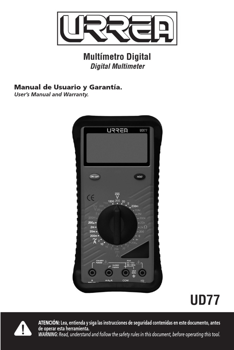
Urrea UD12 Dimensions and installation guide

Multímetro Digital
Digital Multimeter
UD12
ATENCIÓN: Lea, entienda y siga las instrucciones de seguridad contenidas en este docuemento, antes
de operar esta herramienta.
WARNING: Read, understand and follow the safety rules in this document, before operating this tool.
Manual de Usuario y Garantía.
User’s Manual and Warranty.

2
ESPAÑOL
ADVERTENCIA:
FUENTES COMO LAS DE PEQUEÑOS RADIOS PORTÁTILES, TRANSMISORES DE ESTACIONES DE
RADIO, TELEVISIÓN, DE RADIO DE VEHÍCULO Y DE TELÉFONOS CELULARES GENERAN RADIACIÓN
ELECTROMAGNÉTICA QUE PODRÍA INDUCIR VOLTAJES EN LAS PRUEBAS PRINCIPALES DEL
MULTÍMETRO. EN ESOS CASOS LA PRECISIÓN DEL MULTÍMETRO NO ES GARANTIZADA POR
RAZONES FÍSICAS.
CONTENIDO
1. INTRODUCCIÓN 3
2. CONSIDERACIONES DE SEGURIDAD 3
3. INSTRUCCIONES DE OPERACIÓN 3
4. MANTENIMIENTO Y REEMPLAZO DE LA BATERÍA 4
5. ESPECIFICACIONES ELÉCTRICAS 4
6. ESPECIFICACIONES GENERALES 5

3
ESPAÑOL
1. INTRODUCCIÓN
Este medidor manual es un instrumento
operado por batería, diseñado y probado de
acuerdo a la publicación IEC 1010-1 (EN61010-
1) (Categoría III de sobrevoltaje) La directiva
de EMC (EN 50081-1) y otros estándares de
seguridad.
ADVERTENCIA: LEA LAS CONSIDERACIONES
DE SEGURIDAD ANTES DE USAR ESTE MEDIDOR.
2. CONSIDERACIONES DE
SEGURIDAD
Antes de usar el medidor, lea la siguiente
información cuidadosamente. En este manual
la palabra “ADVERTENCIA” es usada para
condiciones y acciones que ponen en riego al
usuario, la palabra “PRECAUCIÓN” es usada
para condiciones y acciones que pueden dañar
el medidor.
Símbolos internacionales.
ADVERTENCIA Voltaje peligroso
(Riesgo de descarga eléctrica)
Corriente Alterna (CA)
Corriente Directa (CD)
Diodo
Tierra (Rango de Voltaje aplicado
permitido entre la terminal de
entrada y tierra)
PRECAUCIÓN
Doble aislamiento
(Protección de clase II)
ADVERTENCIA: OBSERVE TODAS LAS
PRECAUCIONES CUANDO SE MIDA VOLTAJES
ALTOS. APAGUE EL CIRCUITO BAJO PRUEBA,
PONGA ESTE MEDIDOR EN LA FUNCIÓN Y RANGO
DESEADO. CONECTE LAS PUNTAS DE PRUEBA A EL
MEDIDOR Y DESPUÉS AL CIRCUITO BAJO PRUEBA.
APLIQUE POTENCIA NUEVAMENTE. SI LA
LECTURA ES ERRÓNEA DESCONECTE LA POTENCIA
INMEDIATAMENTE Y CHEQUE DE NUEVO TODAS
LAS CONEXIONES.
Lea la siguiente información cuidadosamente antes
de operar o hacer servicio del medidor.
• Nunca trate de medir un voltaje que exceda
los 600 V CD o CA RMS.
• Recuerde que cualquier voltaje por arriba de
los 40 V CD o 25 V CA tienen un serio riesgo de
descarga eléctrica.
• No opere el selector de función mientras el
medidor está conectado a un circuito.
• Retire la potencia del circuito bajo prueba
antes de empezar cualquier trabajo.
• Nunca trate de utilizar el medidor si este o las
puntas de prueba han sido dañadas de alguna
forma.
• Cuando utilice las puntas de prueba aleje sus
dedos de los contactos a probar, siempre tome
las puntas por detrás de las guardas para los
dedos.
• Solo utilice el medidor como está especificado
en el manual. De otra manera la protección que
se provee por el medidor puede ser anulada.
Características.
• Pantalla de 3 1/2 dígitos 2 000 cuentas con
indicadores de polaridad
• Selección de rango manual para Voltajes CA/
CD
• Rango de 200 Ω
• Protección de 600 V para todos los rangos
• Prueba de continuidad - alarma sonora rápida
de continuidad
• Funda Protectora
• Polaridad Automática
• Indicador de batería baja
• Certificado CE
3. INSTRUCCIONES DE OPERACIÓN
Mediciones de Voltajes CD/CA.
ADVERTENCIA: PARA EVITAR RIESGO
DE DESCARGA ELÉCTRICA, DAÑOS A LOS
INSTRUMENTOS Y/O DAÑO AL EQUIPO, LOS

4
ESPAÑOL
VOLTAJES NO DEBEN EXCEDER 600V CD O CA
PICO. NO INTENTE MEDIR NINGÚN VOLTAJE
DESCONOCIDO QUE PUEDA EXCEDER LOS 600
VOLTS CD O CA PICO.
1. Conecte la punta de prueba negra a la
terminal y la punta de prueba roja a la
terminal .
2. Seleccione la función deseada en CD o
CA, aplique las puntas al circuito bajo prueba y
lea la pantalla.
El medidor emite un tono beep cuando aparece
en pantalla (sobrecarga) , entonces el
interruptor debe ser puesto en un rango mas
alto.
En caso de que el voltaje de CD sea negativo el
símbolo, “ ” aparecerá en el lado izquierdo
de la pantalla .
NOTA: Si no sabe el valor del voltaje a ser
medido siempre empiece con el rango más alto
y reduzca el ajuste para obtener una lectura
satisfactoria.
Mediciones de Resistencia y Prueba de
Continuidad.
Cuando se mida resistencia, asegúrese que
el contacto entre las puntas de prueba y el
circuito bajo prueba es bueno. Suciedad, aceite,
soldadura, pasta u otros materiales extraños
afectan seriamente la lectura.
1. Inserte la punta de prueba negra en la
terminal y la punta de prueba roja en la
terminal .
2. Coloque el interruptor de función en 200
. Con las puntas sin contacto la pantalla
debe mostrar .
3. Ponga las puntas de prueba en corto y observe
que la pantalla muestra <0.2 Ω y se emite el tono
beep de continuidad. Si esto no sucede, revise
si las puntas de prueba estén bien insertadas
o posicione el interruptor nuevamente en la
función.
4. Aplique las puntas de prueba al circuito bajo
prueba y lea la medición de resistencia en la
pantalla. Una lectura de 50Ω o menor causará
que se emita el tono beep de continuidad.
4. MANTENIMIENTO Y
REEMPLAZO DE LA BATERÍA
Mantenimiento General.
ADVERTENCIA: PARA EVITAR DESCARGAS
ELÉCTRICAS, REPARACIONES O SERVICIOS
NO CUBIERTOS EN ESTE MANUAL DEBEN
SER ÚNICAMENTE HECHAS POR PERSONAL
CALIFICADO. NO LE HAGA SERVICIO A ESTE
MEDIDOR A MENOS QUE ESTE CALIFICADO PARA
ELLO.
Periódicamente limpie la cubierta con un paño
húmedo y un poco de detergente, no use
solventes abrasivos.
Calibre el medidor una vez al año para mantener
sus especificaciones de desempeño.
Reemplazo de la batería.
El medidor usa una batería 9 V (NEDA 1604 o IEC
6LR61).Para reemplazar la batería, remueva los
dos tornillos de el compartimiento de batería
en la parte
inferior del medidor y levante la tapa del
compartimiento. Reemplace la batería. Inserte
la nueva batería y ponga de nuevo la tapa del
compartimiento y reinstale los tornillos.
Usando las puntas de prueba.
Use únicamente el tipo de puntas de prueba
(UD71TLAC) diseñadas para el instrumento.
5. ESPECIFICACIONES ELÉCTRICAS
Accuracy is given as ± (% of reading) + (number
of least significant digits) at 18°C to 28°C with
relative humidity up to 80%, for a period of one
year after calibration. AC conversions of this

5
ESPAÑOL
Meter are Average responding and calibrated
to the RMS value of a sine wave input.
Función Volts CD
Rango Resolución Precisión
20 V
200 V
600 V
10 mV
100 mV
1 V ±1.5 %+3 dgts
Protección de sobrecarga 600 V
Función Volts CA
(45Hz a 450 Hz)
Rango Resolución Precisión
200 V
600 V 100 mV
1 V ±1.5 %+5 dgts
Protección de sobrecarga 600 V
Función Ohms
Rango Resolución Precisión
200 Ω 0.1 Ω ±1.5 %+5 dgts
Protección de sobrecarga 600 V
Función Continuidad
Rango Resolución Precisión
VOLTAJE DE PRUEBA DE CIRCUITO ABIERTO: 3 V
UMBRAL: Aproximadamente <50 Ω
Protección de sobrecarga 600 V
6. ESPECIFICACIONES GENERALES
Máximo voltaje entre cualquier terminal y
tierra: 600 V
Pantalla Digital: 3 ½ dígitos 2000 cuentas con
indicación automática de polaridad
Tiempo de Lectura: De 2 a 3 lecturas por
segundo
Impedancia de Entrada: 10 M ohm
Temperatura de Almacenamiento: -10 °C a
50 °C (14 °F a 122 °F)
Temperatura de Operación: 0 °C a 40 °C (32
°F a 104 °F)
Altitud: 2000 m (6 562 Pies)
Humedad Relativa: 0% a 80% (0 °C a 35 °C)
- 0% a 70% (35 °C a 45 °C)
Grado de Contaminación: 2
Categoría de Instalación: III
Tipo de Batería: 9 V, NEDA 1604 o IEC 6LR61
Vida de la Batería: 200 hrs. normalmente
(alcalina)
Tamaño (A x A x L): Sin funda: 36 x 70 x 140
mm Con funda: 54 x 80 x 154 mm
Peso: Sin funda: 220 g (7,7 oz) Con funda: 380
g (13,4 oz)
Accesorios: Juego de puntas de prueba, una
batería 9 V, funda protectora e instructivo.

6
ENGLISH
WARNING:
SOURCES LIKE SMALL HAND HELD RADIO TRASCEIVERS, FIXED STATION RADIO AND TELEVISION
TRANSMITTERS, VEHICULE RADIO TRANSMITTERS AND CELLULAR PHONES GENERATE
ELECTROMAGNETIC RADIATION THAT MAY INDUCE VOLTAGES IN THE TEST LEADS OF THE
MULTIMETER CANNOT BE GUARANTEED DUE TO PHYSICAL REASONS.
CONTENT
1. INTRODUCTION 7
2. SAFETY CONSIDERATIONS 7
3. OPERATING INSTRUCTIONS 7
4. MAINTENANCE AND BATTERY REPALCEMENT 8
5. ELECTRICAL SPECIFICATIONS 8
6. GENERAL SPECIFICATIONS 9

7
ENGLISH
1. INTRODUCTION
This Meter is a handheld and battery operated
instrument that is designed and tested
according to IEC Publication 1010-1 (EN 61010-
1) (Overvoltage Category III), the EMC Directive
(EN 50081-0 and EN 50082-1) and other safety
standards.
WARNING: READ “SAFETY CONSIDERATIONS”
BEFORE USING THIS METER.
2. SAFETY CONSIDERATIONS
Before using this Meter, read the following
safety information carefully. In this manual,
the word “WARNING” is used for conditions
and actions that pose hazard(s) to the user; the
word “CAUTION” is used for conditions and
actions that may damage this Meter.
International Symbols.
WARNING Dangerous Voltage
(Risk of electric shock)
Alternating Current (AC)
Direct Current (DC)
Diode
Ground (Allowable applied
voltage range between the input
terminal and earth
CAUTION
Double Insulation
(Protection Class II)
WARNING:OBSERVEALLSAFETYPRECAUTIONS
WHEN MEASURING HIGH VOLTAGES. TURN OFF
POWER TO THE CIRCUIT UNDER TEST, SET THIS
METER TO THE DESIRED FUNCTION AND RANGE,
CONNECT THE TEST LEADS TO THIS METER AND
THEN TO THE CIRCUIT UNDER TEST.
REAPPLY POWER. IF AN ERRONEOS READING IS
OBSERVED, DISCONNECT POWER IMEDIATELY
AND RECHECK ALL SETTINGS AND CONNECTIONS.
Read the following safety information carefully before
attempting to operate or service the meter.
• Never try to measure any voltage which
exceeds 600 V DC or AC RMS.
•
• Remember that any voltage above 40 V DC or
25 V AC may pose a serious shock hazard.
•
• Do not operate the function selector whilst
the Meter is connected to a circuit.
•
• Turn off the power to a circuit under test
before carrying out any work on it.
•
• Do not attempt to use the Meter if either the
Meter or the test leads have been damaged.
•
• When using the test leads keep your fingers
away from probe contacts. Always grip behind
the finger guards on the probes.
•
• Use the Meter only as specified in this manual.
Otherwise, the protection provided by this
Meter may be impaired.
Features.
• 31/2digit2000countdisplaywithannunciators.
• AC/DC voltages-Manual range selection.
• A 200 Ω range.
• Continuity test - fast continuity beeper.
• 600 V input protection on all ranges.
• Protective Holster.
• Auto polarity.
• Battery replacement indicator
• CE - marking certificated.
3. OPERATING INSTRUCTIONS
DC/AC Voltage Measurement.

8
ENGLISH
WARNING: TO AVOID THE RISK OF ELECTRIC
SHOCK, INSTRUMENT DAMAGE AND/OR
EQUIPMENT DAMAGE, INPUT VOLTAGES MUST
NOT EXCEED 600 VOLTS DC OR PEAK AC. DO NOT
ATTEMPT TO TAKE ANY UNKNOWN VOLTAGE
MEASUREMENT THAT MAY BE IN EXCESS OF 600
VOLTS DC OR PEAK AC.
1. Connect the Black test lead to the COM
terminal and the Red test to the V terminal.
2. Set the function switch to your desired DC
V or AC V range and touch the probes to the
circuit under test, and read the display.
The Meter beeps when (overload) is
displayed, then the function switch must be set
to a higher range.
In case of negative DC voltage, “ ” symbol
will appear on the left side of LCD.
NOTE: If you do not know the value of the
voltage to be measured, always start with
the highest range and reduce the setting as
required to obtain a satisfactory reading.
Resistance Measurement and Continuity
Test.
When measuring resistance, make certain that
the contact between the test leads and the
circuit under test is good. Dirt, oil, solder, flux,
or other foreign matter seriously affect the
reading value.
1. Connect the Black test lead to the COM
terminal and Red test lead to the terminal.
2. Set the function switch to 200 . With the
leads open, the Meter should display a on
the LCD.
3. Short the leads and see that the display reads
<0.2 Ω and the continuity beeper sounds. If not,
check the test eads insertion or position of the
function switch again.
4. Touch the test leads to the circuit under test
and read the resistance measurement in the
display. A reading of 50 Ω or less will cause the
continuity beeper to sound.
4. MAINTENANCE AND BATTERY
REPLACEMENT
General Maintenance.
WARNING: REPAIRS OR SERVICING NOT
COVERED IN THIS MANUAL SHOULD ONLY BE
PERFORMED BY QUALIFIED PERSONNEL. TO
AVOID ELECTRICAL SHOCK, DO NOT SERVICE
UNLESS YOU ARE QUALIFIED TO DO SO.
Periodically wipe the case with a damp cloth
and detergent; do not use abrasives or solvents.
Calibrate this Meter once a year to maintain its
performance specifications.
Battery Replacement.
The Meter uses a 9V battery (NEDA 1604 or IEC
6LR61). To replace the battery, remove the two
screws of the battery compartment from the
back of the Meter and lift off the cover of the
compartment. Replace the battery. Reattach
the compartment cover to the back of the
Meter, and reinstall the screws.
Using Test Leads.
Use only the test leads supplied (UD71TLAC)
designed to be used with the instrument.
5. ELECTRICAL SPECIFICATIONS
Accuracy is given as ± (% of reading) + (number
of least significant digits) at 18°C to 28°C with
relative humidity up to 80%, for a period of one
year after calibration. AC conversions of this

9
ENGLISH
Meter are Average responding and calibrated
to the RMS value of a sine wave input.
Function Volts DC
Range Resolution Accuracy
20 V
200 V
600 V
10 mV
100 mV
1 V ±1.5 %+3 dgts
Overload protection 600 V
Function Volts AC
(45Hz to 450 Hz)
Range Resolution Accuracy
200 V
600 V 100 mV
1 V ±1.5 %+5 dgts
Overload protection 600 V
Function Ohms
Range Resolution Accuracy
200 Ω 0.1 Ω ±1.5 %+5 dgts
Overload protection 600 V
Function Continuity
Range Resolution Accuracy
OPEN CIRCUIT TEST VOLTAGE: 3 V
THRESHOLD: Approx. <50 Ω
Overload protection 600 V
6. ESPECIFICACIONES GENERALES
Maximum Voltage between any terminal
and earth: 600 V
Digital Display: 3 ½ digits, 2000 counts with
automatic polarity indication
Reading Time: 2-3 readings per second
Input Impedance: 10M ohm
Storage Temperature: -10 °C to 50 °C (14 °F
to 122 °F)
Operating Temperature: 0 °C to 40 °C (32 °F
to 104 °F)
Altitude: 2 000 m (6 562 feet)
Relative humidity: 0% to 80% (0 °C to 35 °C)
- 0% to 70% (35 °C to 45 °C)
Pollution Degree: 2
Installation Category: III
Battery Type: 9V, NEDA 1604 or IEC 6LR61
Battery Life: 200 hrs. typical (alkaline)
Size (H x W x L): Without Holster 36 x 70 x 140
mm With Holster 54 x 80 x 154 mm
Weight: Without Holster: 220g (7.7 oz) With
Holster : 380g (13.4 oz)
Accessories Supplied: Test leads set, 9 V
battery, Protective Holster and Instruction Sheet

10
NOTAS / NOTES:

11
NOTAS / NOTES:

Póliza de garantía. Este producto está garantizado por URREA HERRAMIENTAS PROFESIONALES, S.A. DE C.V., km 11,5 Carr. A
El Castillo, 45680 El Salto, Jalisco. UHP900402Q29, Teléfono 01 33 3208-7900 contra defectos de fabricación y mano de obra
con su reposición o reparación sin cargo por el período de 1 año. Para hacer efectiva esta garantía, deberá presentar el producto
acompañado de su comprobante de compra en el lugar de adquisición del producto o en el domicilio de nuestra planta mismo
que se menciona en el primer párrafo de esta garantía. En caso de que el producto requiera de partes o refacciones acuda a
nuestros distribuidores autorizados.
Los gastos que se deriven para el cumplimiento de esta garantía serán cubiertos por Urrea Herramientas Profesionales, S.A. de
C.V. Esta garantía no será efectiva en los siguientes casos:
a).- Cuando la herramienta se haya utilizado en condiciones distintas a las normales.
b).- Cuando el producto hubiera sido alterado de su composición original o reparado por personas no autorizadas por el fabri-
cante o importador respectivo.
This product has 1 year warranty by Urrea Herramientas Profesionales S.A. de C.V. against any manufacturing defect, with its
repair or replacement during its life expectancy. The warranty is not applicable if the product does not show the URREA brand,
if the product is worn out by its daily use, shows signs of abuse, damage, its original composition has been altered, or speci-
fies a different warranty. In order to make the warranty effective, the product must be taken to the company or to the place of
purchase along with its receipt.
IMPORTED BY / IMPORTADO POR: URREA HERRAMIENTAS PROFESIONALES S.A. DE C.V. km 11,5 Carretera a El Castillo, C.P.
45680 El Salto, Jalisco, México Tel. 01 (33) 3208-7900 Made in Korea / Hecho en Corea R.F.C. UHP900402Q29 04-I15
SELLO DEL DISTRIBUIDOR
FECHA: / /
UD12
Table of contents
Languages:
Other Urrea Multimeter manuals