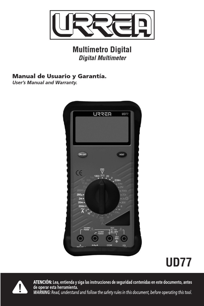
Urrea UD18 Dimensions and installation guide

Multímetro Digital
Digital Multimeter
UD18
ATENCIÓN: Lea, entienda y siga las instrucciones de seguridad contenidas en este documento, antes
de operar esta herramienta.
WARNING: Read, understand and follow the safety rules in this document, before operating this tool.
Manual de Usuario y Garantía.
User’s Manual and Warranty.

2
ESPAÑOL
ADVERTENCIA:
FUENTES COMO LAS DE PEQUEÑOS RADIOS PORTÁTILES, TRANSMISORES DE
ESTACIONES DE RADIO, TELEVISIÓN, DE RADIO DE VEHÍCULO Y DE TELÉFONOS
CELULARES GENERAN RADIACIÓN ELECTROMAGNÉTICA QUE PODRÍA INDUCIR
VOLTAJES EN LAS PRUEBAS PRINCIPALES DEL MULTÍMETRO. EN ESOS CASOS
LA PRECISIÓN DEL MULTÍMETRO NO ES GARANTIZADA POR RAZONES FÍSICAS.
CONTENIDO
1. INTRODUCCIÓN 3
2. CONSIDERACIONES DE SEGURIDAD 3
3. EXPLICACIÓN DE CONTROLES E INDICADORES 4
4. MODO EN ESPERA 4
5. RANGOS DE ENTRADA 5
6. PRUEBA GENERAL Y MEDICIÓN 5
6.1 Medición de Voltaje
6.2 Medición de Resistencia
6.3 Prueba de Diodos y Continuidad
6.4 Medición de Frecuencia
6.5 Medición de Capacitancia
7. FUNCIÓN DE PRUEBA LÓGICA 6
8. MANTENIMIENTO 7
9. DATOS TÉCNICOS 7
10. ESPECIFICACIONES 8

3
ESPAÑOL
1. INTRODUCCIÓN
Este medidor es un instrumento portátil
operado por batería que está diseñado y
probado de conformidad con la Publicación
IEC 1010 (categoría III de sobre voltaje) y otras
normas de seguridad (ver “Datos Técnicos).
ADVERTENCIA: LEA LAS CONSIDERACIONES
DE SEGURIDAD ANTES DE USAR ESTE MEDIDOR.
2. CONSIDERACIONES DE
SEGURIDAD
Antes de usar el medidor, lea la siguiente
información cuidadosamente. En este manual
la palabra “ADVERTENCIA” es usada para
condiciones y acciones que ponen en riego al
usuario, la palabra “PRECAUCIÓN” es usada
para condiciones y acciones que pueden dañar
el medidor.
Símbolos internacionales.
ADVERTENCIA Voltaje peligroso
(Riesgo de descarga eléctrica)
Corriente Alterna (CA)
Corriente Directa (CD)
CD ó CA
Diodo
Capacitor
Tierra (Rango de Voltaje
aplicado permitido entre la
terminal de entrada y tierra)
PRECAUCIÓN
Doble aislamiento
(Protección de clase II)
ADVERTENCIA: OBSERVE TODAS LAS
PRECAUCIONES CUANDO SE MIDA VOLTAJES
ALTOS. APAGUE EL CIRCUITO BAJO PRUEBA,
PONGA ESTE MEDIDOR EN LA FUNCIÓN Y RANGO
DESEADO. CONECTE LAS PUNTAS DE PRUEBA
A EL MEDIDOR Y DESPUÉS AL CIRCUITO BAJO
PRUEBA. APLIQUE POTENCIA NUEVAMENTE. SI LA
LECTURA ES ERRÓNEA DESCONECTE LA POTENCIA
INMEDIATAMENTE Y CHEQUE DE NUEVO TODAS
LAS CONEXIONES.
Consejos de Seguridad.
Exceder los límites especificados para este
medidor es peligroso, y puede exponer al
usuario a daños serios y posiblemente fatales.
Para asegurar la seguridad y el uso apropiado,
por favor siga las indicaciones listadas a
continuación.
• No trate de medir ningún voltaje que exceda
de 750V CD o 750V CA RMS.
• Los voltajes arriba de 60V CD o 25V CA
RMS pueden crear serios riesgos de choque
eléctrico.
• No intente usar este medidor si el medidor o
las puntas de prueba han sido dañadas.
• Apagar la alimentación del circuito bajo
prueba antes de trabajar el circuito. Las
pequeñas cantidades de corriente pueden ser
peligrosas.
• Desconecte el cable de prueba energizado
antes de desconectar la punta común.
• Cuando use las puntas de prueba, mantenga
sus dedos lejos de las puntas de contacto de
los cables. Siempre coloque sus dedos detrás
de las guardas de protección de las puntas de
prueba.
Características.
• Pantalla LCD de 3 ¾ dígitos, 4000 cuentas con
gráfica de barras de 41 segmentos
• Selección de rango manual o automático
• Indicador de Modo en Espera
• Mantener Datos (HOLD)
• Función de Prueba Lógica
• Medición de Capacitancia
• Medición de Frecuencia

4
ESPAÑOL
• Tono beep de continuidad
• Prueba de Diodo
• Funda de protección
• Polaridad automática
• Indicador de reemplazo de batería
3. EXPLICACIÓN DE
CONTROLESE INDICADORES
1. Reemplazar batería
2. Lectura máxima en registro max/min
3. Registro activado máx/min
4. Lectura mínima en registro max/min
5. Modo en espera activado
6. Alarma de continuidad activada
7. Prueba de diodo
8. Congelar datos (Hold)
9. Unidades de medición
10. Escala de visualización análoga
11. Flecha fuera de escala
12. Puntero análogo (41 posiciones)
13. Análogo (+ o – mostrados) muestra
polaridad
14. Rango manual
15. Elegir entre volts CD y CA
16. Modificación de rangos
17. Volts CD/CA
18. Ohm
19. Interruptor giratorio de 6 posiciones
20. Terminal de entrada
21. Terminal común (regreso)
22. Capacitancia
23. Frecuencia
24. Prueba lógica
25. Prueba de continuidad/diodo
Funda y Soporte.
El medidor viene con una funda de plástico
sobrepuesta que absorbe golpes y protege el
medidor contra manejo rudo. La funda está
equipada con un soporte.
4. MODO EN ESPERA
En el modo en espera, la pantalla sólo muestra
STBY parpadeando para conservar la vida
de la batería. Y en este modo solamente el
microprocesador y algunos componentes de
poder están activos para reducir el consumo
de batería. El medidor emite un tono beep y

5
ESPAÑOL
entra en espera sí esta en ENCENDIDO pero
inactivo por más de 30 minutos. Presione
cualquier botón o cambio de función para
reanudar la operación. El modo en espera no
puede ser usado cuando en el medidor está en
modo registro MAX/MIN. Para desactivar el
modo en espera, presione y sostenga el botón
HOLD por 2 segundos mientras presiona el
botón ON/OFF.
5. RANGOS DE ENTRADA
El rango de entrada determina el valor más
alto que el medidor puede medir. La mayoría
de las funciones tienen más de un rango
(ver especificaciones). Si el rango es muy
bajo, la pantalla muestra OFL (sobre flujo o
sobrecarga). Si el rango es muy alto, la pantalla
mostrará menos dígitos de resolución.
Autorango.
El medidor se posiciona en el modo de auto
rango cuando se enciende. En modo de auto
rango, el medidor selecciona el mejor rango
automáticamente.
Selección manual de rango.
El medidor también tiene un modo de rango
manual. En el modo de rango manual, usted
selecciona y asegura el medidor en un rango.
Para seleccionar manualmente un rango:
1. Presionar el medidor está asegurado en el
rango en que está, y se muestra .
2. Presionar para pasar a través de los
rangos. El medidor emite un tono beep
siempre que el rango cambia.
3. Para regresar al rango automático,
presionar por 2 segundos o cambiar
la función de medición. Deja de ser
mostrado en pantalla.
6. PRUEBA GENERAL Y
MEDICIÓN
6.1 Medición de Volts.
ADVERTENCIA: PARA EVITAR RIESGO
DE CHOQUE ELECTRICO, DAÑO DEL
INSTRUMENTO Y/O EQUIPO, LOS
VOLTAJES DE ENTRADA NO DEBEN
EXCEDER DE 750 VOLTS CD O PICO
CA, NO INTENTAR TOMAR NINGUNA
MEDICIÓN DE VOLTAJE DESCONOCIDO
QUE PUEDA EXCEDER DE 750 VOLTS CD
O PICO CA.
1. Inserte las puntas de prueba en las
terminales de entrada.
2. Posicione el interruptor giratorio en la
función de voltaje.
3. Para elegir entre CD y CA, presione .
4. Ponga en contacto los cables con los puntos
de prueba y lea la pantalla. El medidor
emite un tono beep cuando es mostrado
OFL (sobrecarga).
6.2 Medición de Resistencia.
PRECAUCIÓN: APAGUE LA
ALIMENTACIÓN Y DESCARGUE TODOS
LOS CAPACITORES EN EL CIRCUITO QUE
SERÁN PROBADO ANTES DE INTENTAR
LAS MEDICIÓNES DE RESISTENCIA EN
EL CIRCUITO, EL NO HACERLO PUEDE
DAÑAR EL EQUIPO Y/O INSTRUMENTO.
1. Inserte las puntas de prueba en las
terminales de entrada, y apague la
alimentación del circuito bajo prueba. El
voltaje externo a través de los componentes
causa lecturas erróneas.
2. Posicione el interruptor giratorio en la
función ohms.
3. Ponga en contacto los cables con los puntos

6
ESPAÑOL
de prueba y lea la pantalla. El medidor
emite un tono beep cuando es mostrado
OFL (sobrecarga).
6.3 Prueba de Diodos y Continuidad.
1. Inserte las puntas de prueba en las
terminales de entrada.
2. Posicione el interruptor giratorio en la
función de diodo/continuidad. El medidor
selecciona la función de prueba de
continuidad ( ) / diodo ( ).
3. Para probar continuidad, ponga en
contactos los cables con los puntos de
prueba. El tono beep suena continuamente
si existe continuidad (resistencia < 100Ω).
Para elegir encender o apagar el tono
beep en la prueba de continuidad/diodo,
presione . es mostrado cuando el tono
beep está activado.
4. Para probar diodos ponga en contacto los
cables con el diodo. Una caída de voltaje-
directo de aproximadamente 0.6V (normal
para un diodo de silicón) es mostrada si
el diodo es bueno. Invierta los cables. Si
el diodo es bueno, OFL es mostrado. Si el
diodo está en corto, tonos beep sonarán
continuamente en al menos una dirección.
Si el diodo está abierto, OFL es mostrado en
ambas direcciones.
6.4 Medición de Frecuencia.
1. Inserte las puntas de prueba en las
terminales de entrada.
2. Posicione el interruptor giratorio en la
función de frecuencia (Hz).
3. Ponga en contacto los cables con los puntos
de prueba, y lea la pantalla. Si la frecuencia
medición es mayor de 200KHz, será
mostrado OFL (sobrecarga). En frecuencia,
el medidor está siempre en auto rango
y la función de registro MAX/MIN está
desactivada.
6.5 Medición de Capacitancia.
PRECAUCIÓN: DESCARGUE TODOS
LOS CAPACITORES ANTES DE INTENTAR
TOMAR MEDICIÓNES, EL NO HACERLO
PUEDE DAÑAR EL MEDIDOR.
1. Inserte las puntas de prueba en las
terminales de entrada.
2. Posicione el interruptor giratorio en la
función de capacitancia ( ).
3. Ponga en contacto los cables con el capacitor
y lea la pantalla. Cuando mida capacitores
polarizados, asegúrese de conecte el
positivo a la terminal y la negativa a
la terminal COM. La absorción dieléctrica
del capacitor puede causar errores en la
medición. Si es necesaria más descarga, el
medidor muestra mientras que el
capacitor está descargándose.
4. Para salir de capacitancia, cambie la función
de medición.
NOTA: Use el modo de rango manual
para obtener una respuesta más rápida
de lectura cuando mida capacitancia en
los rangos de 1000 μF o 10000 μF.
7. FUNCIÓN DE PRUEBA
LÓGICA
Esta función es ideal para analizar niveles
lógicos digitales y comunicaciones en serie.
Este medidor mide niveles lógicos en
frecuencias arriba de 400 KHz y detecta
pulsos tan angostos como 2,5 μS para aquellos
circuitos de alta velocidad. Cuando esta
función está trabajando, la pantalla muestra
si el punto de prueba es un nivel lógico alto o
bajo o está pulsando o no está activo.
1. Posicione el interruptor giratorio en la
función de prueba lógica (LP).
2. Conecte las puntas de prueba en los puntos
de prueba.

7
ESPAÑOL
3. Si la salida alta está activa por más de un
segundo, este medidor automáticamente
mide el voltaje y lo muestra con dos dígitos
a la derecha junto con una .
Si la salida alta es de más de 39.9 V CD, este
medidor muestra .
Si la salida baja está activa y la salida alta
está inactiva por más de un segundo, este
medidor automáticamente mide el voltaje y lo
muestra en dos dígitos a la derecha junto con
una , cuando pueda ser necesaria una señal
negativa en el segundo dígito. Si la salida baja
es menor de -9,9 V CD, este medidor muestra
.
Si la salida baja y alta han estado activas
durante los últimos segundos, este medidor
muestra .
Si cualquiera de las salidas está activa, este
Medidor muestra .
Cuando las puntas de prueba son retiradas
del circuito bajo prueba, la pantalla mostrará
inmediatamente (abierto).
8. MANTENIMIENTO
ADVERTENCIA: PARA EVITAR
CHOQUE ELECTRICO O DAÑO AL
MEDIDOR, NO PERMITA QUE ENTRE
AGUA DENTRO DE LA CAJA. RETIRE
LAS PUNTAS DE PRUEBA Y CUALQUIER
SEÑAL DE SALIDA ANTES DE ABRIR LA
CUBIERTA.
Limpie periódicamente la caja con un trapo
húmedo y detergente; no use abrasivos o
solventes.
Reemplazo de la batería.
El medidor usa una batería de 9 V (NEDA
1604 o IEC 6F22). Para reemplazar la batería,
retire los dos tornillos del compartimiento
de la batería de la parte trasera del medidor
y levante la cubierta del compartimiento.
Reemplace la batería y reinstale los tornillos.
Servicio y Partes.
Cuando de servicio al medidor, use solamente
las partes de reemplazo especificadas y
unicamente personal calificado puede dar
servicio a este medidor.
9. DATOS TÉCNICOS
Este medidor cumple con las normas de
FCC parte 15. La operación está sujeta a las
siguientes condiciones:
1. Este medidor no causa interferencia
perjudicial.
2. Este medidor debe aceptar cualquier
interferencia recibida, incluyendo
interferencia que pueda causar operación
no deseada.
Voltaje máximo entre cualquier terminal y
tierra física.
Tierra: 750 V
Pantalla: Digital de 3¾ dígitos, 4000 unidades,
actualiza 5 veces cada segundo, Análogo-actualiza
10 veces cada segundo, gráfica de barras de 41
segmentos.
Coeficiente de Temperatura: 0.1 x (precisión
especificada)/°C (<18°C o >28°C)
Temperatura de Operación: 0°C a 40°C (32°F a 104°F)
Humedad de Operación: 0% a 80% RH
Temperatura de Almacenamiento: -20°C a 60°C (-4°F

8
ESPAÑOL
a 140°F)
Tipo de Batería: 9 V, NEDA 1604 o IEC 6F22
Vida de la Batería: 200 horas normalmente (alcalina)
Vibración, golpe: 1 medidor de impacto, Por Mil-T-
28800D para un instrumento Clase 3
Dimensiones (A x A x L):
Sin funda: 36 x 70 x 140 mm
Con funda: 54 x 80 x 154 mm
Peso:
Sin funda: 252 g (8.8 oz.)
Con funda: 425 g (14.9 oz.)
Normas de Seguridad: Diseñado para requerimiento
de Protección clase II para UL 1244, CSA C22.2 NO.
231, ANSI/ISA-S82, Y VDE 0411 Y IEC 1010, sobre
voltaje categoría III.
Regulaciones EMI: Cumple con FCC parte 15, clase B
y VDE 0871 B.
Equipo Estándar: Multímetro, puntas de prueba,
funda, manual del usuario y batería 9 V (instalada).
Límites de medición.
Voltaje CD: 0 a 750V
Voltaje CA: 0 a 750V
Resistencia: 0 a 20MΩ
Capacitancia: 0.001µF a 999µF
Frecuencia: 1 Hz a 200 KHz
Verificación de Continuidad: Tono beep en Aprox.
<100Ω En el rango 400Ω
Función de “Prueba Lógica”: -9.9 V a + 39.9 V CD
(arriba de 400 KHz)
10. ESPECIFICACIONES
La precisión es dada como ± ([% de lectura]
+ [número de dígitos mínimos importantes])
en 18°C a 28°C con humedad relativa hasta
de 80% o un período de un año después de
la calibración. Las conversiones CA son lecturas
promedio CA-acoplada y calibrada al valor
RMS de una entrada de onda sinusoidal:
Función
Volts CD
Rango Resolución Precisión
400 mV
4 V
40 V
400
750 V
0,1 mV
0,001 V
0,01V
0,1 V
1 V
±(0,9% + 2)
Voltaje de entrada
máximo:
750 V CD
Impedancia de entrada
(nominal):
> 10 MΩ < 100 pF
Radio de rechazo modo
común:
> 90 dB en CD, 50 Hz
(1 KΩ sin balance)
Radio de rechazo modo
normal:
> 30 dB en 50 Hz o 60 Hz
Función
Volts CA
Rango Resolución Precisión
4 V *
40 V
400 V
750 V
0,001 V
0,01 V
0,1 V
1 V
±(1,9% + 3)
* Esta precisión en el rango 4 V está garantizada
para 50 Hz a 200 Hz solamente.
Voltaje de entrada
máximo:
750 V CA MÁXIMO (pico)
Impedancia de entrada
(nominal):
> 10 MΩ > 100 pF
(CD acoplado)
Radio de rechazo modo
común:
> 60 dB, CD a 60 Hz

9
ESPAÑOL
Función
Resistencia
Rango Resolución Precisión
400 Ω
4 KΩ
40 KΩ
400 KΩ
4 MΩ
0,1Ω
0,001 KΩ
0,01 Ω
0,1 KΩ
0,001 MΩ
±(0,9% + 2)
20 MΩ 0,01 MΩ ±(1,5% + 3)
Protección de sobrecarga:
600 V CD / CA máximo
(pico)
Voltaje de prueba de
circuito abierto:
< 3,5 V CD
Voltaje de escala completa
a 4 MΩ:
< 450 mV CD En 20 MΩ :
< 2,5 V CD
Corriente de circuito corto:
< 1,5 mA
Prueba de Diodo
Protección de sobrecarga:
600 V CD / CA máximo (pico)
Voltaje de prueba de
circuito abierto:
< 3,5 V CD
Voltaje de escala completa:
1.000 V CD
Corriente de circuito corto:
< 1,5 mA
Prueba de Continuidad
Rango:
400 Ω
Tono beep de continuidad:
Aproximadamente
< 100 Ω
Función
Capacitancia
Rango Resolución Precisión
1,000 μF
10,00 μF
100,0 μF
0,001 μF
0,01 μF
0,1 μF
± (1,7% + 5) *¹
1000 μF 1 μF ± (2,5% + 15)
10000 μF 1 μF ± (10% + 90 ) *²
Protección de sobrecarga:
250 V CD / CA máximo
(pico)
* ¹ La precisión es para los capacitores que tienen absorción dieléctrica ilegible.
*² Precisión típica. Funcionalmente, 1000 μF está en el mismo rango que 10 000 μF.
Función
Frecuencia
Rango Resolución Precisión
1,000 μF
10,00 μF
100,0 μF
0,001 μF
0,01 μF
0,1 μF
± (1,7% + 5) *¹
1000 μF 1 μF ± (2,5% + 15)
10000 μF 1 μF ± (10% + 90 ) *²
Protección de sobrecarga:
250 V CD / CA máximo
(pico)
Prueba Lógica
Entrada baja:
1,2 V
Entrada alta:
1,6 V
Impedancia de entrada:
10 MΩ
Respuesta de frecuencia :
400 KHz
Detecta pulsos tan
angostos como:
2,5 μS
Protección de entrada de
señal máxima:
600 V CD / CA máximo
(pico) para 15 segundos

10
ENGLISH
WARNING:
SOURCES LIKE SMALL HAND HELD RADIO TRASCEIVERS, FIXED STATION
RADIO AND TELEVISION TRANSMITTERS, VEHICULE RADIO TRANSMITTERS
AND CELLULAR PHONES GENERATE ELECTROMAGNETIC RADIATION THAT
MAY INDUCE VOLTAGES IN THE TEST LEADS OF THE MULTIMETER CANNOT BE
GUARANTEED DUE TO PHYSICAL REASONS.
CONTENT
1. INTRODUCTION 11
2. SAFETY CONSIDERATIONS 11
3. EXPLANATION OF CONTROLS AND INDICATORS 12
4. STAND BY MODE 12
5. INPUT RANGES 13
6. GENERAL TESTING AND MEASURING 13
6.1 Measuring Volts
6.2 Measuring Resistance
6.3 Testing Continuity and Diodes
6.4 Measuring Frequency
6.5 Measuring Capacitance
7. FUNCIÓN DE PRUEBA LÓGICA 14
8. MAINTENANCE 15
9. TECHNICAL DATA AND SPECIFICATIONS 15
10. SPECIFICATIONS 16

11
ENGLISH
1. INTRODUCTION
This Meter is a handheld and battery
operated instrument that is designed and
tested according to IEC Publication 1010
(Overvoltage Category lll) and other safety
standards (see “Technical Data”).
WARNING: READ “SAFETY
CONSIDERATIONS” BEFORE USING
THIS METER.
2. SAFETY CONSIDERATIONS
Before using this Meter, read the following
safety information carefully. In this manual,
the word “WARNING” is used for conditions
and actions that pose hazard(s) to the user;
the word “CAUTION” is used for conditions
and actions that may damage this Meter.
International Symbols.
WARNING Dangerous Voltage
(Risk of electric shock)
Alternating Current (AC)
Direct Current (DC)
Either DC or AC
Diode
Capacitor
Ground (Allowable applied
voltage range between the
input terminal and earth
CAUTION Refer to the user’s
manual before using this Meter
Double Insulation (Protection
Class II)
WARNING: OBSERVE ALL SAFETY
PRECAUTIONS WHEN MEASURING
HIGHER VOLTAGES. TURN OFF POWER
TO THE CIRCUIT UNDER TEST, SET THIS
METER TO THE DESIRED FUNCTION AND
RANGE, CONNECT THE TEST LEADS TO
THIS METER AND THEN TO THE CIRCUIT
UNDER TEST. REAPPLY POWER. IF AN
ERRONEOUS READING IS OBSERVED,
DISCONNECT POWER IMMEDIATLY
AND RECHECK ALL SETTINGS AND
CONNECTIONS.
Safety Tips.
Exceeding the specified limits of this Meter
is dangerous, and can expose the user to
serious and possibly fatal injury. To ensure
safe and appropriate use, please follow the
safety guide lines below:
• Do not try to measure any voltage that
exceeds 750 DC V or 750 AC V peak.
• Voltages above 60 V DC or 25V AC RMS
may constitute a serious shock hazard.
• Do not attempt to use this Meter if either
the Meter or the test leads have been
damaged.
• Turn off power to the circuit under test
before cutting, unsoldering, or breaking
the circuit. Small amounts of current can
be dangerous.
• Disconnect the live test lead before
disconnecting the common test lead.
• When using the test leads, keep your
fingers behind the finger guards on the
probes.
Features.
• 3 ¾ digit, 4000 count LCD with 41 segment
bar graph
• Auto Range or Manual Range Selection
• Standby Mode Indicator
• Data Hold
• Logic Probe Function
• Capacitance Measurement
• Frequency Measurement
• Fast Continuity Beeper
• Diode Test

12
ENGLISH
• Rubber Boot
• Auto Polarity
• Battery Replacement Indicator
3. EXPLANATION OF
CONTROLS AND INDICATORS
1. Replace battery
2. Maximum reading in max/min
recording
3. Max/min recording enabled
4. Minimum reading in max/min
recording
5. Stand by enabled
6. Continuity beeper enabled
7. Diode test
8. Display hold
9. Measurement units
10. Analog display scale
11. Off scale arrow
12. Analog pointer (41 positiones)
13. Analog (+ or - shown) display polarity
14. Manual range
15. Toggle between volts DC and AC
16. Ranging operations
17. Volts DC/AC
18. Ohms
19. 6 Position rotary switch
20. Input jack
21. Common (return) jack
22. Capacitance
23. Frequency
24. Logic probe
25. Continuity/diode test
Holster and Stand.
The Meter comes with a snap-on holster
that absorbs shocks and protects the
Meter from rough handling. The holster is
equipped with a stand rest.
4. STAND BY MODE
In Standby mode, the display just except
blinking STBY (STAND BY) goes to
preserve battery life. And in this mode
only microprocessor and a few power
components are active to reduce battery
consumption.
The Meter beeps and enters Standby if

13
ENGLISH
it is ON but inactive for more than 30
minutes. Press any pushbutton or change
the measurement function to resume
operation. Standby is not allowed if the
Meter in the MAX/MIN Recording mode.
To disable Standby mode, press and hold
down the HOLD pushbutton for 2 seconds
while pressing the ON/OFF pushbutton.
5. INPUT RANGES
The input range determines the highest
value that the Meter can measure. Most
functions have more than one range (see
Specifications). If the range is too low, the
display shows OFL (overflow or overload). If
the range is too high, the display will show
fewer digits of resolution.
Autoranging.
The Meter defaults to autoranging
mode when you turn the Meter on. In
autoranging mode, the Meter selects the
best range automatically.
Manually Selecting a Range.
The Meter also has a manual range mode.
In manual range mode, you select and lock
the Meter in a range.
To manually select range:
1. Press the meter is locked in the range it
is in, and is displayed.
2. Press to step through the ranges.
The Meter beeps whenever the range
changes.
3. To return to autorange, press for 2
seconds or change the measurement
function. is no longer displayed.
6. GENERAL TESTING AND
MEASURING
6.1 Measuring Volts
WARNING: O AVOID THE RISK OF
ELECTRICAL SHOCK, INSTRUMENT
DAMAGE AND/OR EQUIPMENT
DAMAGE, INPUT VOLTAGES MUST
NOT EXCEED 750 VOLTS DC OR PEAK
AD. DO NOT ATTEMPT TO TAKE ANY
UNKNOWN VOLTAGE MEASUREMENT
THAT MAY BE IN EXCESS OF 750
VOLTS DC OR PEAK AC.
1. Insert the leads in the jacks.
2. Set the rotary switch to the voltage
function.
3. To toggle between DC and AC, press .
4. Touch the probes to the test points, and
read the display. The Meter beeps when
OFL (overload) is displayed.
6.2 Measuring Resistance.
CAUTION: TURN OFF POWER AND
DISCHARGE ALL CAPACITORS ON
CIRCUIT TO BE TESTED BEFORE
ATTEMPTING IN-CIRCUIT RESISTANCE
MEASUREMENTS. FAILURE TO DO SO
MAY END UP IN EQUIPMENT AND/OR
INSTRUMENT DAMAGE.
1. Insert the test leads in the jacks, and
turn off power to the circuit under test.
External voltage across the components
causes erroneous readings.
2. Set the rotary switch to the Ω function.
3. Touch the probes to the test points, and
read the display. The Meter beeps when
OFL (overload) is displayed.
6.3 Testing Continuity and Diodes.
1. Insert the test leads in the jacks.

14
ENGLISH
2. Set the rotary switch to the continuity
/ diode function. The Meter selects the
continuity ( )diode ( ) test function.
3. To test continuity, touch the probes
to the test points. The beeper sounds
continuously if continuity exists
(resistance <100Ω). To toggle the beeper
on or off in continuity/diode test, press
. is displayed when the beeper is
enabled.
4. To test diodes, touch the probes to
the diode. A forwardvoltage drop of
about 0.6V (typical for a silicon diode)
is displayed if the diode is good. Reverse
the probes. If the diode is good, OFL is
displayed. If the diode is shorted, the
beeper sounds continuously in at least
one direction.If the diode is open, OFL is
displayed in both directions.
6.4 Measuring Frequency
1. Insert the test leads in the jacks.
2. Set the rotary switch to the frequency
function (Hz).
3. Touch the probes to the test points,
and read the display. If the measured
frequency is greater than 200 KHz. OFL
(overload) is displayed.
6.5 Measuring Capacitance
CAUTION: DISCHARGE ALL
CAPACITORS BEFORE ATTEMPTING TO
MAKE MEASUREMENTS. FAILURE TO
DO SO CAN RESLUT IN DAMAGES TO
THE METER.
1. Insert the test leads in the jacks.
2. Set the rotary switch to the capacitance
function ( ).
3. Touch the probes to the capacitor, and read
the display. When measuring polarized
capacitors, be sure to connect the positive
to the terminal and the negative to
the COM terminal. Capacitor dielectric
absorption can cause measurement errors.
If more discharge is necessary, the Meter
displays ( ) while the capacitor is
discharging.
4. To exit capacitance, change the
measurement function.
NOTE: Use manual range mode to
get faster response of reading when
measuring capacitance in the ranges of
1000μF or 10000μF.
7. LOGIC PROBE FUNCTION
This Function is ideal for analyzing digital logic
levels and serial communications.
This Meter measures logic levels at frequencies
up to 400 KHz and detects pulses as narrow as
2.5μS for those high speed logic circuits. When
this function is working, the displayed shows if
the test points at a logic level high or low or is
pulsing or is not active.
1. Set the rotary switch to the logic probe
function (LP).
2. Connect the test leads to the test point.
3. If the high output is active for more
than one second, this Meter automatically
measures the voltage and displays it in two
right most digits along with a .
If the high output is more than 39.9 V DC, this
Meter displays a .
If the low output is active and the right output
has been inactive for more than one second
this Meter automatically measures the voltage
and displays it in the two right most digits
along with a , when a negative sign may be
needed in the 2nd digit. If the low output is

15
ENGLISH
less than -9.9 V DC, this Meter displays a .
If both the low output and the high output
have been active within the last second, this
Meter displays a .
If neither output is active, this Meter displays
an .
When the test leads are removed from the
circuit under test, the display will immediately
show an (open).
8. MAINTENANCE
WARNING: TO AVOID ELECTRICAL
SHOCK OR DAMAGE TO THE METER,
DO NOT GET WATER INSIDE THE CASE.
REMOVE THE TEST LEADS AND ANY
INPUT SIGNALS BEFORE OPENING THE
CASE.
Periodically wipe the case with a damp
cloth and detergent; do not use abrasives or
solvents.
Battery Replacement.
The Meter uses a 9V battery (NEDA 1604 or
IEC 6F22).
To replace the battery, remove the two
screws of the battery compartment from the
back of the Meter and lift off the cover of
the compartment. Replace the battery and
reinstall the screws.
Service and Parts.
When servicing the meter, use only the
replacement parts sepcified and this meter
should be serviced only by a qualified
personnel.
9. TECHNICAL DATA
This Meter complies with Part 15 of FCC
Rules. Operation is subject to the following
conditions.
1. This Meter may not cause harmful
interference.
2. This Meter must accept any interference
received, including interference received
that may cause undesired operation.
Maximum Voltage between any Terminal and
Earth. Ground: 750V
Display: Digital - 3¾ digits, 4000 counts,
updates 5/sec Analog Updates 10/sec, 41
segment bargraph.
Temperature Coefficient:
0.1x (specified
accuracy)/ °C(<18°C or >28°C)
Operating Temperature:
0°C to 40°C (32°F to
104°F)
Operating Humidity:
0% to 80% RH
Storage Temperature:
-20°C to 60°C ( -4°F to
140°F)
Battery Type:
9V, NEDA 1604 or IEC 6F22
Battery Life:
200 hours typical (alkaline)
Shock, Vibration:
1 meter shock. Per MIL-T-28800D
for a Class 3 instrument.
Dimensions (H x W x L):
Without Holster: 36 x 70 x 140 mm
With Holster: 54 x 80 x 154 mm
Weight:
Without Holster: 252g (8.8 oz)
With Holster: 425g (14.9 oz)
Safety Standars:
Designed to protector class ll
requirement to UL 1244, CSA C22.2 No. 231, ANSI/
ISA-S82, and VDE 0411, and IEC 1010 Over-voltage
Category III.
EMI Regulations:
Complies with FCC Part 15, Class
B, and VDE0871 B.
Standard Equipment:
Meter, Test-leads, Holster,
User’s manual and 9V battery (installed).

16
ENGLISH
Measurement limits.
DC Voltage: 0 to 750V
AC Voltage: 0 to 750V
Resistance: 0 to 20 MΩ
Capacitance: 0.001 µF to 9999 µF
Frequency: 1 Hz to 200 KHz
Continuity Check: Beep to Approx. < 100Ω in the
400Ω range
“Logic Probe” Function: -9.9V to +39.9V DC (Up to
400 KHz)
10. SPECIFICATIONS
Accuracy is given as ± (% of reading) + (number of
least significant digits) at 18° to 28 °C with relative
humidity up to 80%, or a period of one year after
calibration. AC conversions are AC-coupled, average
responding, and calibrated to the RMS value of a sine
wave input:
Function
DC Volts
Range Resolution Accuracy
400 mV
4 V
40 V
400
750 V
0,1 mV
0,001 V
0,01V
0,1 V
1 V
±(0,9% + 2)
Maximum input voltage:
750 V DC
Input impedance
(nominal):
> 10 MΩ < 100 pF
Common mode rejection
ratio:
> 90 dB at DC, 50 Hz
(1 KΩ unbalanced)
Normal mode rejection
radio:
> 30 dB at 50 Hz
or 60 Hz
Function
AC Volts
Range Resolution Accuracy
4 V *
40 V
400 V
750 V
0,001 V
0,01 V
0,1 V
1 V
±(1,9% + 3)
*This accuracy in the 4V range is guaranteed for
50Hz to 200 Hz only.
Maximum input voltage:
750 V AC maximum
(peak)
Input impedance
(nominal):
> 10 MΩ > 100 pF
(AC coupled)
Common mode rejection
ratio:
> 60 dB, DC to 60 Hz
Function
Resistance
Range Resolution Accuracy
400 Ω
4 KΩ
40 KΩ
400 KΩ
4 MΩ
0,1Ω
0,001 KΩ
0,01 Ω
0,1 KΩ
0,001 MΩ
±(0,9% + 2)
20 MΩ 0,01 MΩ ±(1,5% + 3)
Overload protection:
600 V DC / AC maximum
(peak)
Open circuit test voltage:
< 3,5 V DC
Full scale voltage to 4 MΩ:
< 450 mV DC at 20 MΩ :
< 2,5 V DC
Short circuit current:
< 1,5 mA

17
ENGLISH
Diode test
Overload protection:
600 V DC / AC
maximum
(peak)
Open circuit test voltage:
< 3,5 V DC
Full scale voltage:
1.000 V DC
Short circuit current:
< 1,5 mA
Continuity test
Range:
400 Ω
Continuity beeper:
Approx. < 100 Ω
Function
Capacitance
Range Resolution Accuracy
1,000 μF
10,00 μF
100,0 μF
0,001 μF
0,01 μF
0,1 μF
± (1,7% + 5) *¹
1000 μF 1 μF ± (2,5% + 15)
10000 μF 1 μF ± (10% + 90 ) *²
Overload protection:
250 V DC / AC maximum
(peak)
*¹. The accuracy is for capacitors that have negligible dielectric absorption.
*². Typical accuracy. Functionally, 1000μF is in the same range as 10,000μF.
Function
Frequency
Range Resolution Accuracy
1,000 μF
10,00 μF
100,0 μF
0,001 μF
0,01 μF
0,1 μF
± (1,7% + 5) *¹
1000 μF 1 μF ± (2,5% + 15)
10000 μF 1 μF ± (10% + 90 ) *²
Overload protection:
250 V DC / AC máximo
(pico)
Logic probe
Low threshold:
1,2 V
High threshold:
1,6 V
Input impedance:
10 MΩ
Frequency response:
400 KHz
Detects pulses as
narrow as:
2,5 μS
Max. signal input
protection:
600V DC / AC peak
for 15 sec

18
NOTAS / NOTES:

19
NOTAS / NOTES:

Póliza de garantía. Este producto está garantizado por URREA HERRAMIENTAS PROFESIONALES,
S.A. DE C.V., km 11,5 Carr. A El Castillo, 45680 El Salto, Jalisco. UHP900402Q29, Teléfono 01
33 3208-7900 contra defectos de fabricación y mano de obra con su reposición o reparación sin
cargo por el período de 1 año. Para hacer efectiva esta garantía, deberá presentar el producto
acompañado de su comprobante de compra en el lugar de adquisición del producto o en el domi-
cilio de nuestra planta mismo que se menciona en el primer párrafo de esta garantía. En caso de
que el producto requiera de partes o refacciones acuda a nuestros distribuidores autorizados.
Los gastos que se deriven para el cumplimiento de esta garantía serán cubiertos por Urrea Her-
ramientas Profesionales, S.A. de C.V. Esta garantía no será efectiva en los siguientes casos:
a).- Cuando la herramienta se haya utilizado en condiciones distintas a las normales.
b).- Cuando el producto hubiera sido alterado de su composición original o reparado por personas
no autorizadas por el fabricante o importador respectivo.
This product has 1 year warranty by Urrea Herramientas Profesionales S.A. de C.V. against any
manufacturing defect, with its repair or replacement during its life expectancy. The warranty is not
applicable if the product does not show the URREA brand, if the product is worn out by its daily
use, shows signs of abuse, damage, its original composition has been altered, or specifies a differ-
ent warranty. In order to make the warranty effective, the product must be taken to the company or
to the place of purchase along with its receipt.
IMPORTED BY / IMPORTADO POR: URREA HERRAMIENTAS PROFESIONALES S.A. DE C.V. km
11,5 Carretera a El Castillo, C.P. 45680 El Salto, Jalisco, México Tel. 01 (33) 3208-7900 Made in
Korea / Hecho en Corea R.F.C. UHP900402Q29 04-I15
SELLO DEL DISTRIBUIDOR
FECHA: / /
UD18
Table of contents
Languages:
Other Urrea Multimeter manuals