Urrea USCS2 Dimensions and installation guide

USCS2
ATENCIÓN: Lea, entienda y siga las instrucciones de seguridad contenidas en este
documento, antes de operar esta herramienta.
WARNING: Read, understand and follow the safety rules in this document, before operating this tool.
Careta para Soldar Electrónica Solar
Electronic Solar Welding Helmet
Manual de Usuario y Garantía
User’s Manual and Warranty

2
ESPAÑOL
1. INFORMACIÓN TÉCNICA
Campo de visión: 90 x 40 mm.
Control de oscurecimiento:
Estado claro DIN 4
Estado oscuro DIN 9-13 Ajuste externo.
Velocidad de cambio:
Claro-oscuro 0.3 ms
Tiempo de Demora:
Claro-Oscuro 0.1 a 1seg
Sensitividad y Velocidad de Cambio:
Ajuste sin cambios.
Protección UV/IR: Hasta sombra DIN16.
Temperatura de Operación:
-5 Cº a + 55 Cº.
Fuente de Poder:
Asistencia por celdas solares, dentro de
baterías de Litio.
Control del lente: Encendido: Automático
Apagado: Automático después de 15
minutos.
Certificaciones y estándares:
EN 379 EN 175 B EN 166 B
Material del Casco:
PP (a prueba de fuego).
Peso total: 480 grs.
2. INSTRUCCIONES DE ENSAMBLE
CAMBIAR LA MICA DE PROTECCIÓN
1.Asegurese de que la careta cuente
siempre con el lente protector interior
y exterior.
2.Estos lentes de protección deben de
remplazarse si están rotos, dañados
o cubiertos con salpicaduras de
soldadura a medida que se pierde la
visión en ellos.
3.Los lentes protectores exteriores e
interiores son consumibles y deben ser
remplazados regularmente con partes
genuinas y certificadas.
COLOCACIÓN DEL AJUSTE DE MATRACA
1.Instale la suspensión removiendo las
perillas de roscado (una a la vez) y
apriételas una vez más en su lugar una
vez que haya colocado la suspensión a
través de los hoyos laterales del casco.
2.Gire la perilla de roscado en la parte
posterior de la suspensión de matraca
para ajustarla a la medida del usuario.
3. ÁREA DE TRABAJO
• Mantenga su área de trabajo limpia y
bien iluminada.
• No use el equipo electrónico en
atmósferas explosivas, tales como estar
en la presencia de líquidos flamables,
gases o polvo. Los productos eléctricos
generan chispas, las cuales pueden
provocar incendios.
4. USO Y CUIDADO DEL EQUIPO
• Los materiales que están en contacto
con la piel del usuario puede causar
reacciones alérgicas a personas
susceptibles.
• Esta careta no brinda protección
ilimitada para ojos, oídos y cara.
• Este careta no es recomendable para
soldadura con láser y oxyacetileno.
• No utilice esta careta mientras trabaje
con o cerca de explosivos o líquidos
corrosivos.
• Nunca deje esta careta sobre una

3
ESPAÑOL
superficie caliente.
• Inspeccione frecuentemente la mica.
Remplace inmediatamente si esta
rayada, quebrada o picada.
5. PRECAUCIONES
ATENCIÓN: Para reducir el riesgo de sufrir lesiones
graves durante su uso, siga estas instrucciones:
• Antes de utilizar esta careta de soldador
por primera vez, deberá de remover la
cubierta protectora que cubre el lente
en ambos lados.
• Asegúrese de que el casco esté siempre
equipado con el lente protector interno
y externo.
• El lente protector interno es fácilmente
removible empujándolo hacia afuera
desde dentro del casco. Para insertar
el lente, coloque el lente bajo las dos
pestañas que se ubican en ambos lados
de la abertura principal.
• El lente exterior se mantiene en
posición gracias a un clip plástico. Para
retirarlo mueva el clip interno hacia
el centro del lente. Entonces el clip
puede ser removido y cambiar el lente.
Para ajustar el clip, inserte un lado en
la ranura y posteriormente empuje el
otro lado en su lugar.
• Estos lentes de protección deben ser
reemplazados en caso de rotura, daño
o que se cubran de salpicaduras de
soldadura a medida que se pierde la
visión en ellos.
6. INSTRUCCIONES DE OPERACIÓN
Presione el botón de “Prueba del
lente”antes de empezar a soldar.
Antes de soldar, la ventana debe estar
en el modo de luz DIN4 para que
pueda observar adecuadamente la
pieza. El lente se oscurecerá de manera
automática cuando se genere un arco de
soldadura. Pruebe el lente encendiendo
un fósforo o un encendedor delante
de la ventana para revisar su operación
antes de comenzar a soldar. NO UTILICE
SU CARETA SI NO ESTÁ FUNCIONANDO
ADECUADAMENTE.
9
10
11
12
13
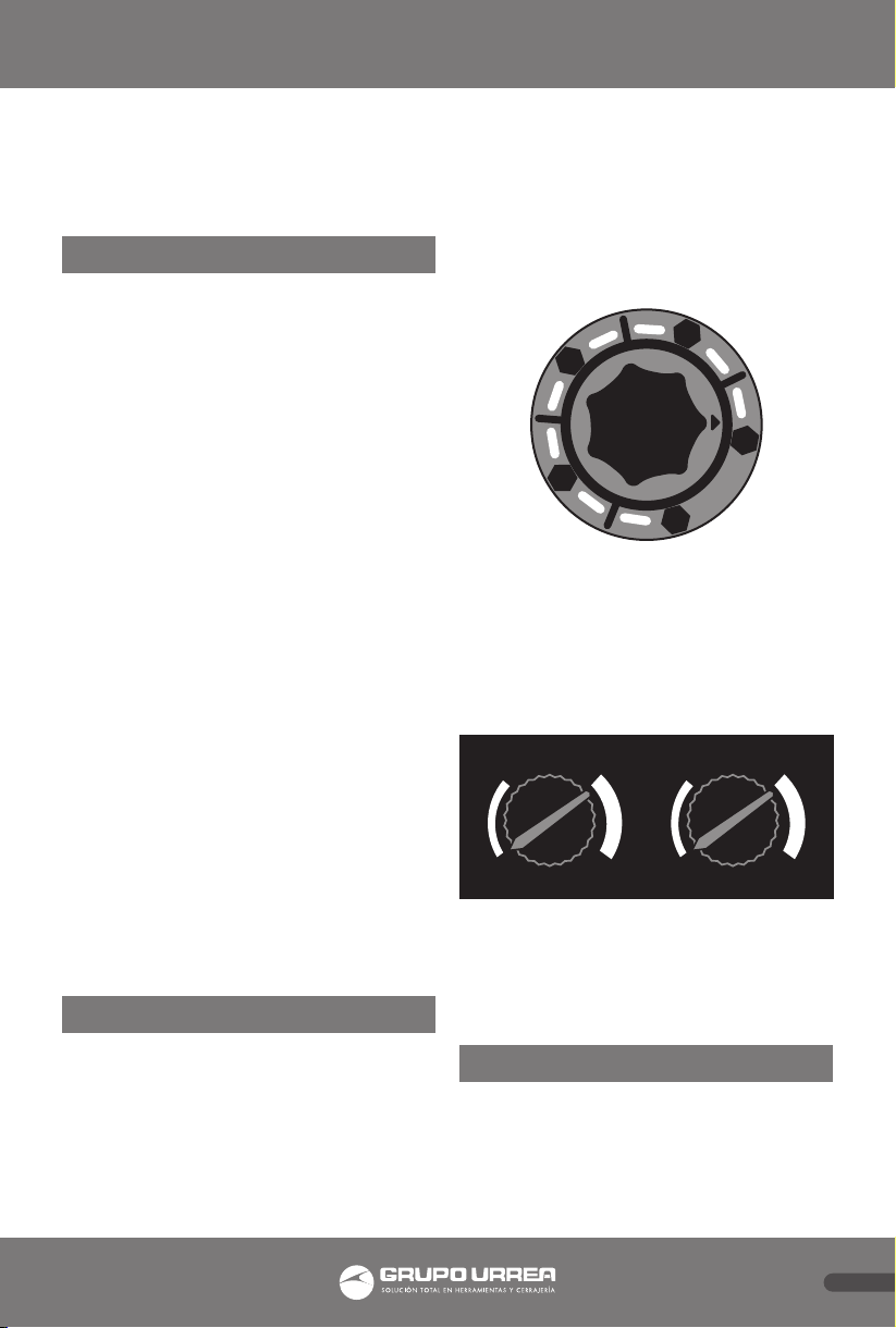
Cambie el grado de oscurecimiento
entre 9 y 13 como usted lo desee usando
la perilla de ajuste variable.
Ajuste la sensibilidad y tiempo de
retardo como lo deseé, usando la perilla
de ajuste variable.
LO HI
S
E
N
S
I
T
I
V
I
T
Y
MINM AX
D
E
L
A
Y
T
I
M
E
Cuando no se utilice el casco por más
de 15 minutos el casco se apagará de
manera automática NO hay botón de
apagado.
7. CUIDADO Y MANTENIMIENTO
• El lente de filto debe limpiarse cuando
la cubierta interior o exterior sea
remplazada.
• Limpielo con un trapo limpio y seco.

4
ESPAÑOL
NOTA: SMAW: Soldadura por arco de metal blindado, SAW: Blindados semi-automático de soldadura, MIG
(pesado): MIG sobre metales pesados, PAC: De corte por plasma de arco, MIG (ligero): MIG sobre aleaciones
ligeras, PAW: Soldadura por arco de plasma, TIG, GTAG: Soldadura por arco de tungsteno (GTAW, TIG)
PROCESO DE
SOLDADURA
CORRIENTE (AMPERAJE)
10
20
30
40
60
80
100
125
150
175
200
225
250
275
300
350
400
450
500
600
SMAW 9 10 11 12 13 14
MIG (pesado) 10 11 12 13 14
MIG (ligero) 10 11 12 13 14 15
TIG, GTAW 9 10 11 12 13 14
MAG/CO2 10 11 12 13 14 15
SAW 10 11 12 13 14 15
PAC 11 12 13
PAW 9 10 11 12 13 14 15
• Aplique desinfectante común con un
trapo o papel limpios. NO LO APLIQUE
DIRECTAMENTE AL FILTRO DEL LENTE.
NO USE ALCOHOL PARA LIMPIAR.
• Reemplace las partes con piezas
originales únicamente.
8. SOLUCIÓN DE PROBLEMAS
No hay cambio de estado.
El lente permanence
claro y no se oscurece
cuando se está
soldando.
Pare de inmediato de soldar, revise
las recomedaciones de sensividad y
ajústela. Limpie la cubierta y el sensor,
asegúrese de que no hay obstrucciones.
El lente automático
permanece oscuro
una vez que el arco
de soldadura terminó,
o permanece oscuro
cuando aún sin la
presencia de arco de
soldadura.
Ajuste la sensitividad haciendo
pequeños ajustes al control
cambiándolo hacia “Lo” en situaciones
de luz extrema quizá sea necesario bajar
los niveles circundantes de luz.
Nota: Asegúrese de que los sensores estén limpios y
de cara al arco de soldadura, ángulos de más de 45°
o más no le permitirán al arco de soldadura alcanzar
los sensores.
Durante la prueba o uso, en cualquier caso de mal
funcionamiento por favor suspenda el uso y contacte
a su proveedor o agente de ventas.
9. CERTIFICACIONES
Los filtro de soldadura son probados
para protección ocular por las siguientes
instituciones:
DIN Prüf-und Zertifizierungsstelle für
Augenschutz, Alboinstr. 56, D-12103
Berlin, notified body 0196, el cual provee
aprobaciones y sistemas de calidad bajo
el control de la Comisión Europea, El
Ministerio Alemán del trabajo y las
oficinas Centrales de las provincias.
Por lo tanto estamos autorizados a usar
los siguientes simbolos:
EN 379 EN 175 B EN 166 B
GUÍA DE SOMBRAS

5
ENGLISH
1. TECHNICAL DATA
Viewing Field: 90 x 40 mm.
Shade Control:
Light States DIN 4
Dark States DIN 9-13 Outside
adjustment.
Switching Time: Light - Dark 0.3.
Delay Time: Dark - Light 0.1 a 1.
Sensitivity & Delay Time:
Stepless adjustment.
UV/IR Protection:
Up to Shade DIN16.
Operating Temperature:
-5 Cº to + 55 Cº.
Power Supply: Solar cells assist, Inside
Lithium Batteries.
Lens Control:
Auto-on, Auto-off 15 minutes (when not
on welding).
Standards:
EN 379 EN 175 B EN 166 B
Helmet Material: PP (Fireproofing).
Total Weight: 480 grs.
2. ASSEMBLY INSTRUCTIONS
REPLACING THE PROTECTION LENS
1.Ensure that the helmet is always fitted
with an outer and Inner protection
lens.
2.These protection lenses must be
replaced if broken, damaged or
covered with welding spatter to the
extent that vision is impaired.
3.Outer and Inner protection lenses are
consumables and must be replaced
regularly with genuine certified spare
parts..
HEADGEAR INSTALLATION
1.Install headgear by removing threaded
knobs (one at a time) and fasten again
after placing each threaded stud
through the larger holes on the sides
of the helmet.
2.Rotate the adjustment knob at the rear
of the headgear assembly to fit the
users head.
3. WORK AREA
• Keep your work area clean and well lit.
• Do not use electronic equipment in
explosive atmospheres, such as being
in the presence of flammable liquids,
gases or dust. Electrical products
generate sparks, which can cause fires.
4. TEAM USE AND CARE
• Materials that may get in contact with
the wearers skin could cause Allergic
reactions to susceptible individuals.
• Welding Helmets do not provide
unlimited eye, ear and face protection.
• This Helmet is not suitable for laser
welding & Oxyacetylene.
• Do not use this welding helmet while
working with or around explosive or
corrosive liquids.
• Never place this Helmet and Auto-
Darkening filter on a hot surface.
• Inspect the lens frequently. Immediately
replace any scratched, cracked, or
pitted cover lenses or auto-lenses.

6
ENGLISH
5. CAUTIONS
ATTENTION: To reduce the risk of serious injury
during use, follow these instructions.
• Before using this welding helmet for
the first time the protective film that
covers the protection lenses must be
removed from both sides of the lens.
• Make sure the helmet is always
equipped with internal and external
protective lens.
• The inner lens protector is easily
removable by pushing outward from
inside the hull. To insert the lens, place
the lens under the two tabs that are
located on both sides of the main
opening.
• The outer lens is held in position by a
plastic clip. To remove the inner clip
move toward the center of the lens.
Then the clip can be removed and
change the lens.To adjust the clip,
insert one side into the slot and then
push the other side into place.
• These goggles must be replaced in case
of breakage, damage or be covered
with spatter as vision is lost on them.
6. OPERATING INSTRUCTIONS
Press ‘Lens Test’ button on the lens
before starting welding.
Before welding, the window will be in
light DIN 4 state and you can see the
work piece. The lens will automatically
darken when an arc is struck. Test the
lens by striking a lighter or match to test
the lens operation before striking an
arc on the work piece for the first time.
DO NOT USE IF LENS IS NOT OPERATING
PROPERLY.
9
10
11
12
13
Change dark shade between 9 and 13 as
desired by using the variable adjustment
knob.
Adjust the Sensitivity and Delay Time as
desired by using the variable adjustment
Knob.
LO HI
S
E
N
S
I
T
I
V
I
T
Y
MINM AX
D
E
L
A
Y
T
I
M
E
When helmet is not used for 15 minutes
the power will automatically shut-off.
There is no OFF switch.
7. CARE AND MAINTENANCE
• The filter lens should be cleaned when
the inner or outer cover lens were
replaced.
• Wipe with clean dry cloth
• Apply the ordinary disinfectant with
a clean cloth or paper towel. DO NOT
APPLY CLEANER DIRECTLY TO THE
FILTER LENS. DO NOT USE ALCOHOL
TO CLEAN
• Replace parts with our genuine parts
replacements only.

7
ENGLISH
8. TROUBLESHOOTING
Not switching
Auto lens stays light
and will not darken
when welding.
Stop welding immediately: Review the
sensitivity recommendations and adjust
sensitivity. Clean Lens cover and sensors
of any obstructions.
Auto lens stays dark
after the weld arc
is extinguished, or
the auto-lens stays
dark when no arc is
present.
Fine-tune the sensitivity setting by
making small adjustments to the control
by turning it toward the ‘Lo’ setting.
In extreme light conditions, it may be
necessary to reduce the surrounding
light levels.
Note: Making sure the sensors are clean and facing
the arc; angles of 45°or more any not allow the arc
light to reach the sensors.
During test or using, in case of any malfunction,
please suspend using it and contact the local sales
agent.
9. CERTIFICATION
The welding filters are tested for eye
protection by the following notified
body:
DIN Prüf-und Zertifizierungsstelle für
Augenschutz, Alboinstr. 56, D-12103
Berlin, notified body 0196, that provides
approval and continual quality system
under the control of the European
Commission, the German Ministry for
Work and the Central Office of the
Provinces.
We are therefore allowed to use the
following marks:
EN 379 EN 175 B EN 166 B
NOTA: SMAW: Shidlded Metal Arc Welding, SAW: Shielded Semi-Automatic Welding, MIG (heavy): MIG on
heavy metals, PAC: Plasma Arc Cutting, MIG (light): MIG on light alloys, PAW: Plasma Arc Welding, TIG, GTAG:
Tungsten Arc Welding(GTAW, TIG)
WELDING
PROCESS
ARC CURRENT (AMPERES)
10
20
30
40
60
80
100
125
150
175
200
225
250
275
300
350
400
450
500
600
SMAW 9 10 11 12 13 14
MIG (heavy) 10 11 12 13 14
MIG (light) 10 11 12 13 14 15
TIG, GTAW 9 10 11 12 13 14
MAG/CO2 10 11 12 13 14 15
SAW 10 11 12 13 14 15
PAC 11 12 13
PAW 9 10 11 12 13 14 15
SHADE GUIDE TABLE

Póliza de garantía. Este producto está garantizado por URREA HERRAMIENTAS PROFESIONALES, S.A. DE C.V., km 11,5 Carr. A El Castillo,
45680 El Salto, Jalisco. UHP900402Q29, Teléfono 01 33 3208-7900 contra defectos de fabricación y mano de obra con su reposición o repar-
ación sin cargo por el período de 10 años. Para hacer efectiva esta garantía, deberá presentar el producto acompañado de su comprobante de
compra en el lugar de adquisición del producto o en el domicilio de nuestra planta mismo que se menciona en el primer párrafo de esta garantía.
En caso de que el producto requiera de partes o refacciones acuda a nuestros distribuidores autorizados.
Los gastos que se deriven para el cumplimiento de esta garantía serán cubiertos por Urrea Herramientas Profesionales, S.A. de C.V. Esta garantía
no será efectiva en los siguientes casos:
a).- Cuando la herramienta se haya utilizado en condiciones distintas a las normales.
b).- Cuando el producto hubiera sido alterado de su composición original o reparado por personas no autorizadas por el fabricante o importador
respectivo.
This product has 10 years warranty by Urrea Herramientas Profesionales S.A. de C.V. against any manufacturing defect, with its repair or
replacement during its life expectancy. The warranty is not applicable if the product does not show the URREA brand, if the product is worn out
by its daily use, shows signs of abuse, damage, its original composition has been altered, or specifies a different warranty. In order to make the
warranty effective, the product must be taken to the company or to the place of purchase along with its receipt.
IMPORTADO POR / IMPORTED BY: URREA HERRAMIENTAS PROFESIONALES S.A. DE C.V. km 11,5 Carretera a El Castillo, C.P. 45680 El Salto,
Jalisco, México Tel. 01 (33) 3208-7900 Made in China / Hecho en China R.F.C. UHP900402Q29 04-D16
SELLO DEL DISTRIBUIDOR
FECHA: / /
USCS2
Table of contents
Languages:
Other Urrea Welding Accessories manuals
Popular Welding Accessories manuals by other brands

Lincoln Electric
Lincoln Electric DH-10 Operator's manual

SteelMax
SteelMax ARC Runner Operator's manual

Dräger
Dräger X-plore 8000 Instructions for use

Miller Electric
Miller Electric 300909 owner's manual

Lincoln Electric
Lincoln Electric IM812-A Operator's manual

Lincoln Electric
Lincoln Electric MINIFLEX K2376-1 Technical specifications