US Automatic 050551 User manual

WIRELESS KEYPAD 050551
INTRODUCTION........................................2
Main Features.............................................2
Packaging inventory...................................2
Technical specications..............................3
MOUNTING DIAGRAM..............................3
POWER SUPPLY.......................................4
BATTERY
Battery low..................................................4
Accessing the battery.................................4
Extra battery...............................................4
PROGRAMMING..................................... 5
Master Password ..................................... 5
Create Accesscode .................................. 5
Changing the security code...................... 6
Deleting a single access code.................. 7
Erasing all access codes.......................... 7
Changing Master password...................... 7
Set Master password back to
factory defaults......................................... 7
Temporary access codes ........................ 8
Night Light ON / OFF programming........... 8
WARRANTY............................................. 8
TABLE OF CONTENTS
Create Communication with Receiver ...... 5
Compatible with all USAutomatic receivers
Part # 030200, 030205 and 030207

2
www.usautomatic.com
1Introduction
The Wireless Keypad 050551 is a radio keypad operating at 433.92 MHz. The radio
transmission is enabled only after entering a valid access code. The internal memory can store
up to 256 different access codes, 256 temporary codes and 1 Master code. This keypad has
4 unique transmitting channels controlling up to 4 different receiver channels. This feature
makes it easy to use 1 keypad to control multiple gate systems individually or simply have 2
unique access codes controlling the two channel (P1, P2) receiver on a single gate system.
FCC ID: PWJRKPU
The product fully complies with the European directive 2014/53/EU “RED” and Part. 15 of
FCC Rules. Operation is suject to the following two conditions:
1. This device may not cause harmful interferences;
2. This device must accept interference that may cause undesired operation.
•Die-casted aluminum cover
•Quarter-turn Keyed lock protection
•Goose Neck compatible mounting plate
•Stainless keypad with blue backlight
•Night light controlled by a twilight sensor
•Night light ON/OFF programable
•Battery supply or 12/24 Vac/dc external supply selectable
• Radio transmission
•256 permanent or temporary 5-digit access codes
• 1 Master code
•Code PUK ( password unblocking key)
•Internal buzzer
7emporary disabling for multiple wrong codes
,ILQFRUUHFWDFFHVVFRGHVDUHDWWHPSWHGWKHNH\SDGLVGLVDEOHGIRUVHFRQGV
Main features
Packaging inventory
1 keypad
1/4 - 20 x 1/2 in Bolts
1/4 - 20 nut
External Tooth
Lockwasher type 2 x keys for
Key Number
622
#
*
Fig. 1
•Hold Open code via programming to the P2 channel in receiver / Latch Mode
•
Changes or modifications not expressly approved by the party responsible for compliance could
void the user's authority to operate the equipment. In cases where the manual is provided only
in a form other than paper, such as on a computer disk or over the internet.

3
www.usautomatic.com
Number of keys....................................12
Number of channels.............................4
Supply...................................................Battery 3 Vdc or Wired 12/24 AC/DC
Battery duration....................................about 24 months - using one battery
Battery type............................... ...........Lithium CR123A
Current consumption battery.................Less than 200 μA with night light ON
Operating frequency.............................433.92 MHz
Modulation........................................... AM/ASK
E.r.p.: ...................................................150 μW
Security Code combinations number....19683
Access codes........................................256
Temporary access codes......................256
Transmission duration...........................until press / 1 sec.
Range in open space............................typically 229 to 492 ft / 70 to 150 m
Operating temperature..........................from 14 °F to 131 °F
Dimensions...........................................6.1” x 4.52” x 1.96”
Weight..................................................10.5 oz / 300 gr
IP Protection Grade..............................IP55
Technical specications
2Mounting diagram
Fig. 2
Goose-neck xing plate
1/4 - 20 Bolts
1/4 - 20 nut
Current consumption wired........:.......... Less than 3 mA with night light ON
4Battery
4
www.usautomatic.com
Battery Low
The limit is about 2.7V. Battery-low status is indicated by the backlitkeys blinking.
Accessing the battery
To access the battery, remove keypad from back plate, then remove the 4xM3
screws that hold the internal cover to the front panel.
4x M3x5
Fig. 5
Lithium Battery
CR123A 3 Vdc
+
_
Slot for extra battery
CR123A Snap out the
pcb to open the
window that hosts
the battery
Internal cover
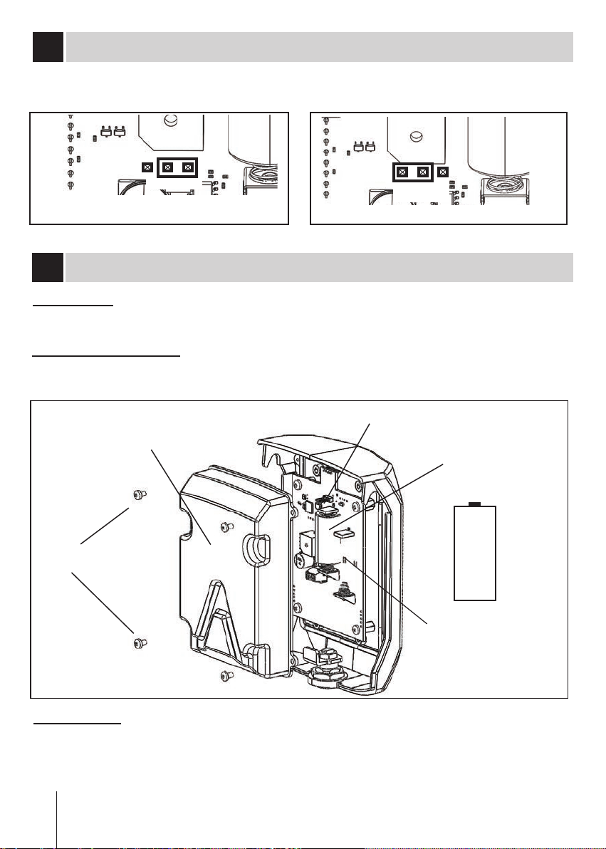
3 Power supply
The keypad can be powered externally with 12/24 Vac/dc, selecting the power
mode with the jumper J1.
Power selection
jumper
J1 = ON : Battery CR123A J1 = OFF: 12/24 Vac/dc
J1
J1
Fig. 3Fig. 4
Extra battery
Expected single battery life is 2 years, if desired a second battery can be
installed CR123A ( not provided ). For its installation, snap out the pcb under
the second battery holder and Insert the battery with the positive pole upwards.

5
www.usautomatic.com
5 Programming
Terms to Understand
Access Code – Is the 5 digit code entered on the keypad to operate the gate.
Option available is to create a code containing less than 5 numbers and use the # sign as the
last key in the code. Example code "5#" or "1234#" the # is part of the access code.
ACCESS CODE CAN NOT BE THE SAME AS THE MASTER PASSWORD.
Master Password – The 5-digit code used to access programming features. Factory default
is “11111”. This should be changed for security reasons.
NOT USED TO OPEN GATE- CANNOT BE THE SAME AS THE PUK or ACCESS CODE.
Channel 1 – P1 (relay 1) is pre-wired to the Push Button input.
Channel 2 – P2 (relay 2) is pre-wired to the “Open/Free Exit” input.
Keypad Security Code (Dip Switch Code) – This code makes your keypad unique to your
installation. Keypad does not have dip switches like the transmitter; instead it has virtual dip
switches which may be programmed.
PUK Code – “Password Unblocking Key.” The PUK code is located inside the keypad and is
needed when the master password has been lost. Record PUK code: ____________
Quick beeps – the keypad is sending a signal to the receiver. Valid access code was entered.
NOTE: Do not install keypad until
“Create Communication with Receiver" has been completed.
Create Access Code: code you use to operate the gate
•Enter the current Master Password
•Enter “9”. If correct, 2 short beeps (if 1 long beep is heard, start over with first step)
•Enter the new Access Code (up to 5 digits), if less than 5 digits, “#” is required.
•Enter “9”.
•Enter the new Access Code again to verify.
•Enter “1”, “2”, “3”, “4” identifying which keypad channel the Access Code is
Create Communication with Receiver
•Enter the Access Code created above
•Holding the last key of the code - keypad beeps while last key is depressed.
•Press the P1 button on the receiver and hold until LD light comes ON.
Programming is complete
•
*For Open Only or Hold Open function program to P2 channel.
*For Hold Open function receiver P2 channel must be set to Latch Mode.
Latch mode - press the P2 button on receiver and hold once the LD light comes ON
immediately release and press the P1 button one time.
Example:
Access code created using a 1 in the last step could be programmed to P1 channel. Access
code created with a 2 in the last step could be programmed to P2 channel. If this was done
then both access codes would have to create communication with receiver in the steps below.
learned to. If correct, 2 short beeps (If 1 long beep, start over with first step).
Enter # to exit (long Beep) or wait for time-out (long Beep) or start again from
step 2 to add more access codes.
6
www.usautomatic.com
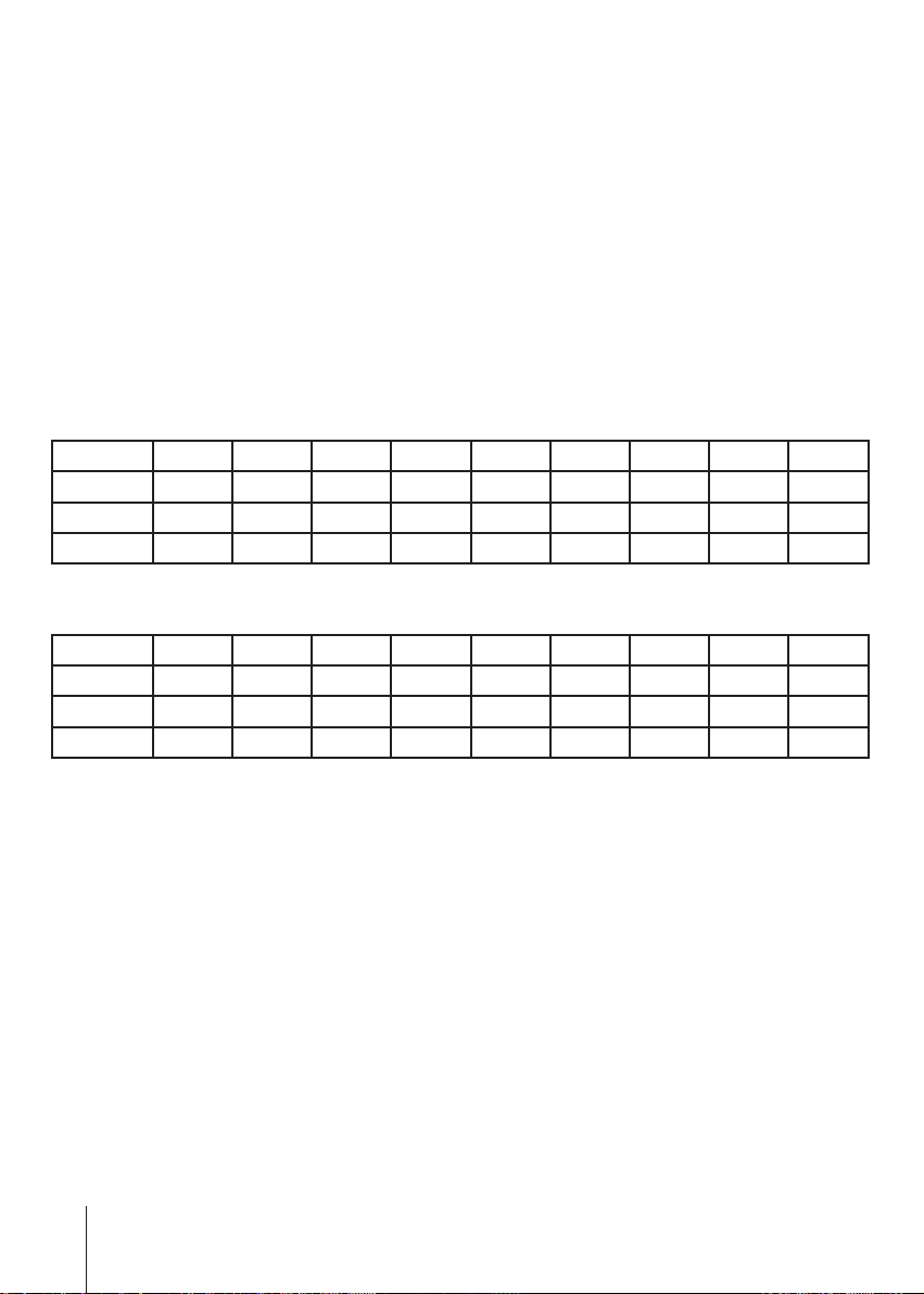
Keypad Dipswitches -This keypad has virtual dipswitches
The virtual dipswitch contains nine 3-position switches. The default Security Code
has all nine switches in the center position. To ensure neighboring keypads do not
interfere with each other, the virtual switches should be positioned in a random
pattern, using the following procedure.
Example of random positioning of the virtual dip-switches to create a Security
Code
To enter the Security Code, enter the dip-switch number, followed by the dip-switch
position character. The Security Code would be entered as:
1# 20 3* 4* 5# 6* 7# 80 9*
Dip pos. 123456789
# X X X
0 X X
*X X X X
Switch number
Use table below to create a random pattern and enter the resulting Security Code in
the following procedure.
Dip pos. 123456789
#
0
*
• Enter the Master Password.
•Enter “6”. If correct, 2 short beeps (if 1 long beep is heard, start over with first
step);
•Enter the Security Code created in the table in the previous column. If correct,
2 short beeps after each switch number and switch position combination is entered.
•Enter “#”.
•Enter “6”. If correct, 2 short beeps (if 1 long beep is heard, start over with first
step).

7
www.usautomatic.com
Deleting a single access code
Erasing all access codes
• Enter the Master Password.
•Enter “7”. If correct, 2 short beeps (if 1 long beep is heard, start over with rst step)
• Enter the Access Code to be deleted.
• Enter “7”.
• Reenter the Access Code to be deleted.
•Enter “7”. If correct, 2 short beeps (if 1 long beep is heard, start over with rst step)
• Enter the Master Password.
•Enter “7”. If correct, 2 short beeps (if 1 long beep is heard, start over with rst step)
• Reenter the Master Password.
• Enter “7”.
• Reenter the Master Password.
•Enter “7”. If correct, 2 short beeps (if 1 long beep is heard, start over with rst step)
Changing the Master Password
•Enter the current Master Password
•Enter “8”. If correct, 2 short beeps (if 1 long beep is heard, start over with rst step)
• Enter the Master Password (up to 5 digits), if less than 5 digits, “#” is required.
• Enter “8”.
• Enter the Master Password again to verify.
•Enter “8”. If correct, 2 short beeps (If 1 long beep is heard, start over with first step.
Setting the Master Password back to Factory Default: (11111)
•Enter “11111.”
•Enter “8” (long beep).
• Enter PUK code. (*)
• Enter “8”.
•Enter PUK code to conrm.
•Enter “8” (2 beeps).
Master password reset complete.
(*) : The 5 digit PUK code is located on a label in the battery compartment and must be
kept in a safe place by the end user.
Record Master Password here for future reference: _________________
Record PUK code here for future reference: _________________
USAutomatic, LLC warrants this product to be free of defects in materials and workmanship for
1 YEAR. For a period of 1 YEAR following purchase USAutomatic, LLC. will repair or replace the
product free of charge, including parts, shop labor and return shipping and handling.
This warranty does not cover the plastic case from normal wear, the battery or damage due to
misuse of the keypad.
To have the product sent for warranty consideration, it must be returned with the proof of purcha-
se and a return authorization number. To obtain a return authorization number please call
1-972-221-7000 or 888-204-0174 for assistance.
The return authorization number must be clearly marked on the outside of the return package or
it may not be accepted.
USAutomatic, LLC
170 Valley Ridge Blvd.
Lewisville, TX 75057
1-972-221-7000 or 888-204-0174
www.usautomatc.com
8Warranty
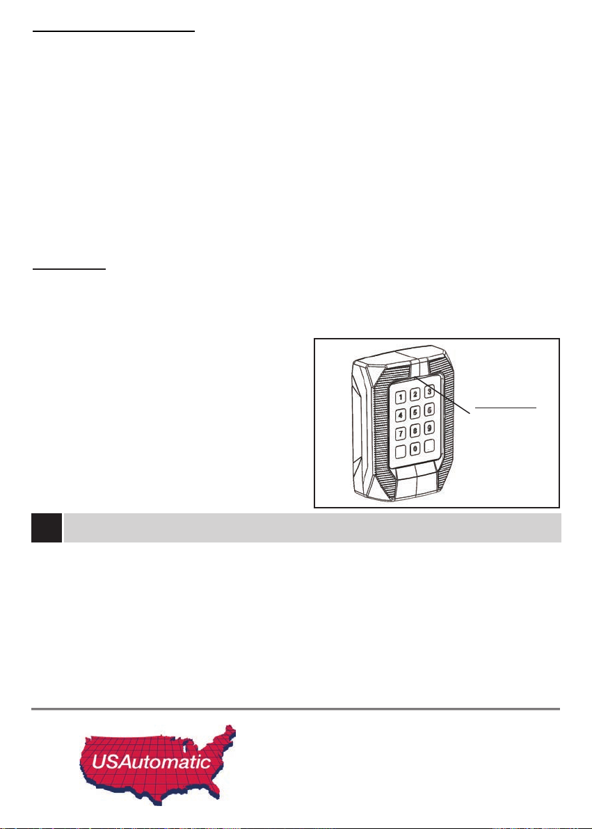
Night Light
The keypad night light provides a low level of lighting to assist in locating the
keypad in the dark. This option can be programmed to an ON or OFF setting. The
default setting is 'ON'. If 'ON' is selected light sensor will turn on night light once it is
dark. Light level sampling is taken every 60 seconds.
• Enter master password
•Enter ‘5’ 2 short beeps
•Enter '1'
Temporary Access Code
Temporary access code may be set for a 1 time activation or up to 9 activations.
The procedure to insert it is:
•Enter the current Master Password
•Enter ‘9’ 2 short beeps
• Enter the temporary code
•Enter ‘9’
•Re enter the temporary code
•Enter ‘#’
•Enter number of possible activations (‘1’ .. ‘9’)
•Enter the channel to be activated (‘1’ .. ‘4’)
#
*
Night light
Fig. 6
• Enter master password
•Enter ‘5’ 2 short beeps
•Enter '2'
Night light 'OFF'
Night light 'ON'
Rev C
This manual suits for next models
3
Table of contents
Other US Automatic Keypad manuals


