DESIGN BY U.S BLASTER - P.O. Box 5376 - Carefree - AZ 85377-USA.
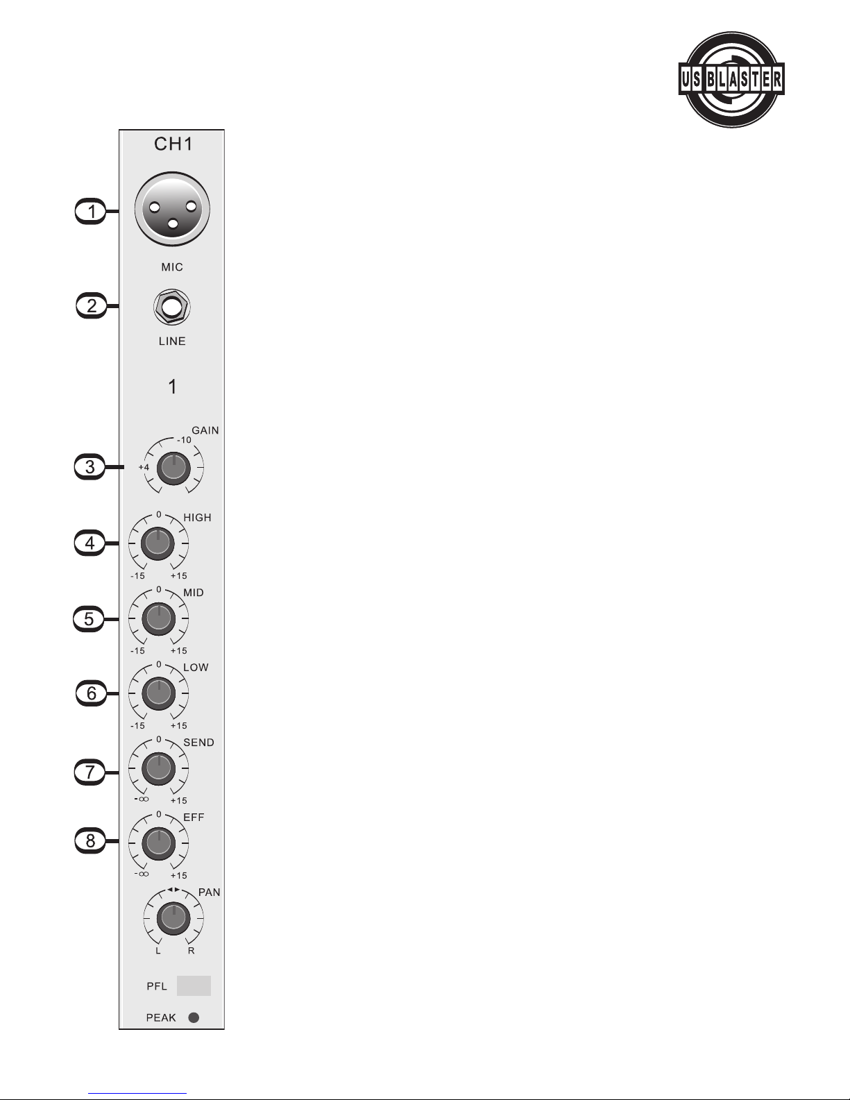
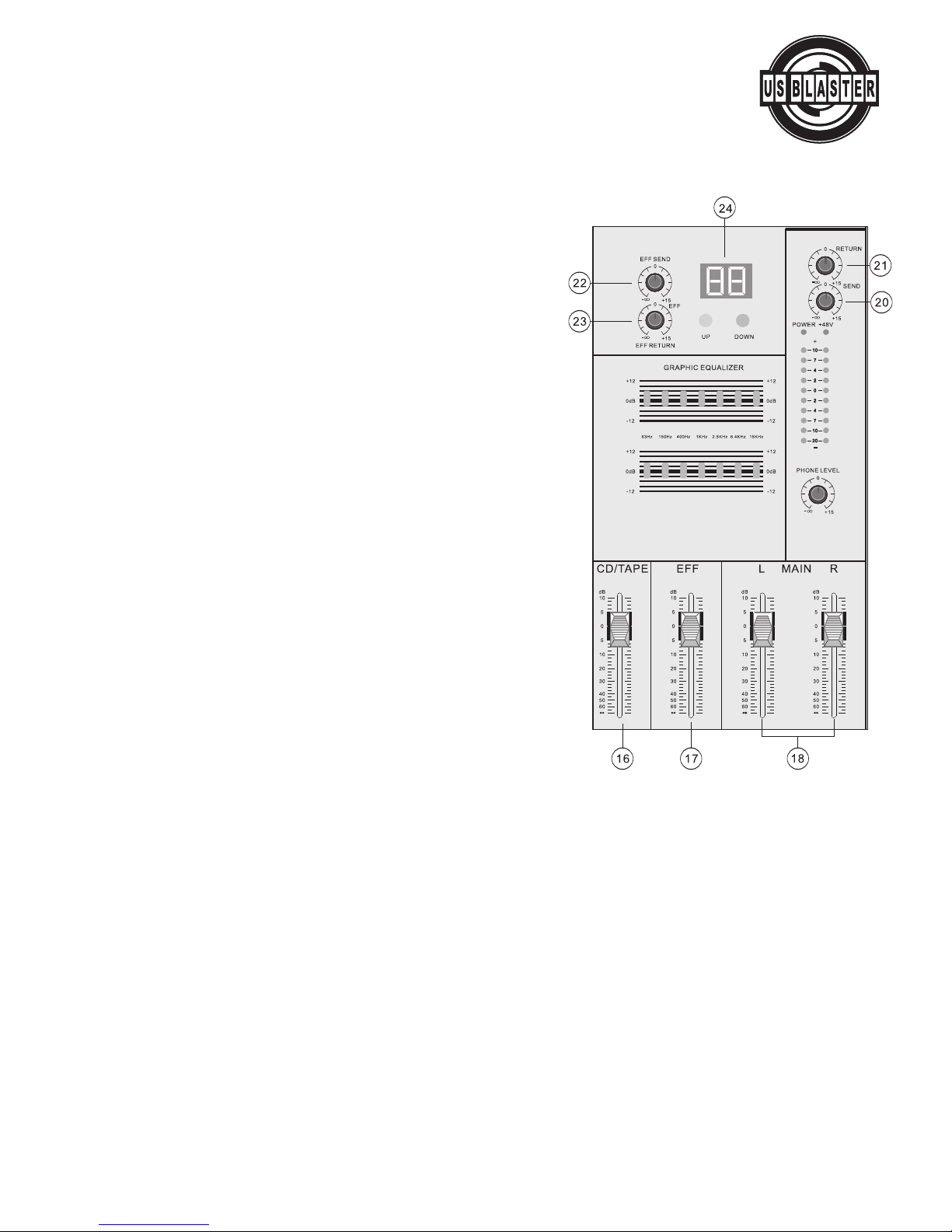
USB 7015
Console mixer
ALGEMENE VEILIGHEIDSVOORSCHRIFTEN
- Lees altijd eerst de gebruiksaanwijzing voordat u een apparaat gaat gebruiken.
- Bewaar de handleiding zodat elke gebruiker hem eerst kan doorlezen.
- Apparaat binnenshuis en niet in vochtige ruimtes gebruiken.
- Verwijder of plaats een stekker nooit met natte handen resp. uit en in de wandkontakt doos.
- Indien zowel stekker en/of netsnoer als snoeringang-in-het-apparaat beschadigd zijn dient dit
door een vakman hersteld te worden.
- Bij onweer altijd de stekker uit het stopcontact halen, zo ook wanneer het apparaat een poos
niet gebruikt wordt.
-Bij het verwijderen van een stekker uit het stopcontact nooit aan het netsnoer trekkken.
- Apparaat zodanig installeren dat er voldoende koeling mogelijk is.
- Toestel niet in de buurt van warmtebronnen en/of in direct zonlicht gebruiken.
-Zorg ervoor dat er geen kleine objecten of vloeistoffen in het toestel kunnen binnendringen.
-Toestel alleen reinigen met een licht vochtige stofvrije doek, geen reinigingsmiddelen of
oplosmiddelen gebruiken!
- Het toestel bevat buiten de in de gebruiksaanwijzing genoemde onderdelen geen onderdelen die
door de gebruiker vervangen of gerepareerd kunnen worden.
- Indien het toestel defect is, moet dit hersteld worden door een door US Blaster voorgeschreven
reparatiebedrijf.
-Het apparaat buiten bereik van kinderen houden.
Bewaar de verpakking zodat, indien het apparaat defect is, u dit in de
originele verpakking kunt opsturen om beschadigingen te voorkomen.
Voer zelf geen reparaties uit aan het apparaat; in élk geval vervalt de totale garantie.
Ook mag het apparaat niet eigenmachtig worden gemodificeerd, ook in dit geval vervalt de tota-
le garantie. Tevens vervalt de garantie bij ongevallen en beschadigingen in élke vorm t.g.v.
onoordeelkundig gebruik en/of het niet in acht nemen van de waarschuwingen in het algemeen
en gestelde in deze gebruiksaanwijzing. US Blaster Europe aanvaardt geen enkele aansprakelijk-
heid in geval van persoonlijke ongelukken als gevolg van het niet naleven van veiligheidsinstruc-
ties en waarschuwingen.Dit geldt ook voor gevolgschade in wélke vorm dan ook.