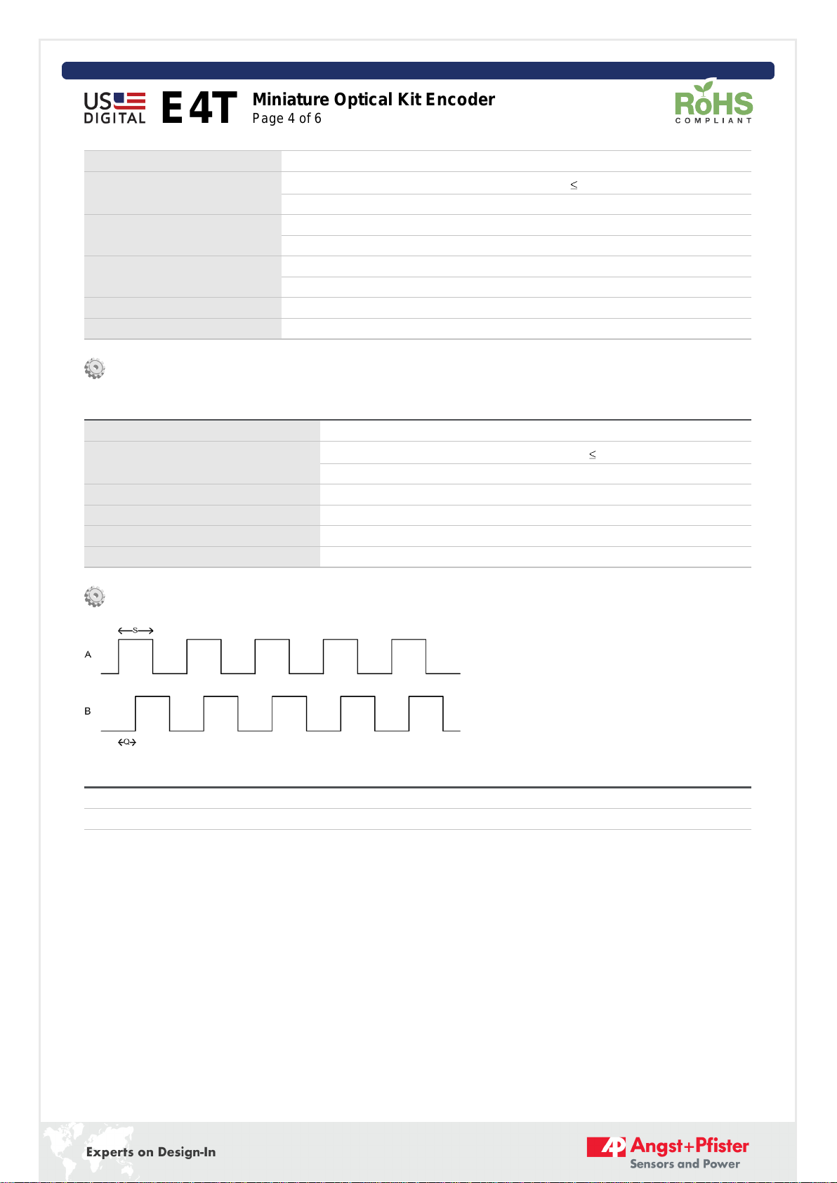
Environmental
Parameter Value Units
Operating Temperature -20 to 100 C
Electrostatic Discharge, IEC 61000-4-2
Single-ended (-S version)
Differential (-D version) ± 12
± 7 kV
Shock, 6 millisecond, half-sine 75 G
Vibration (20Hz to 2kHz, sinusoidal) 20 G
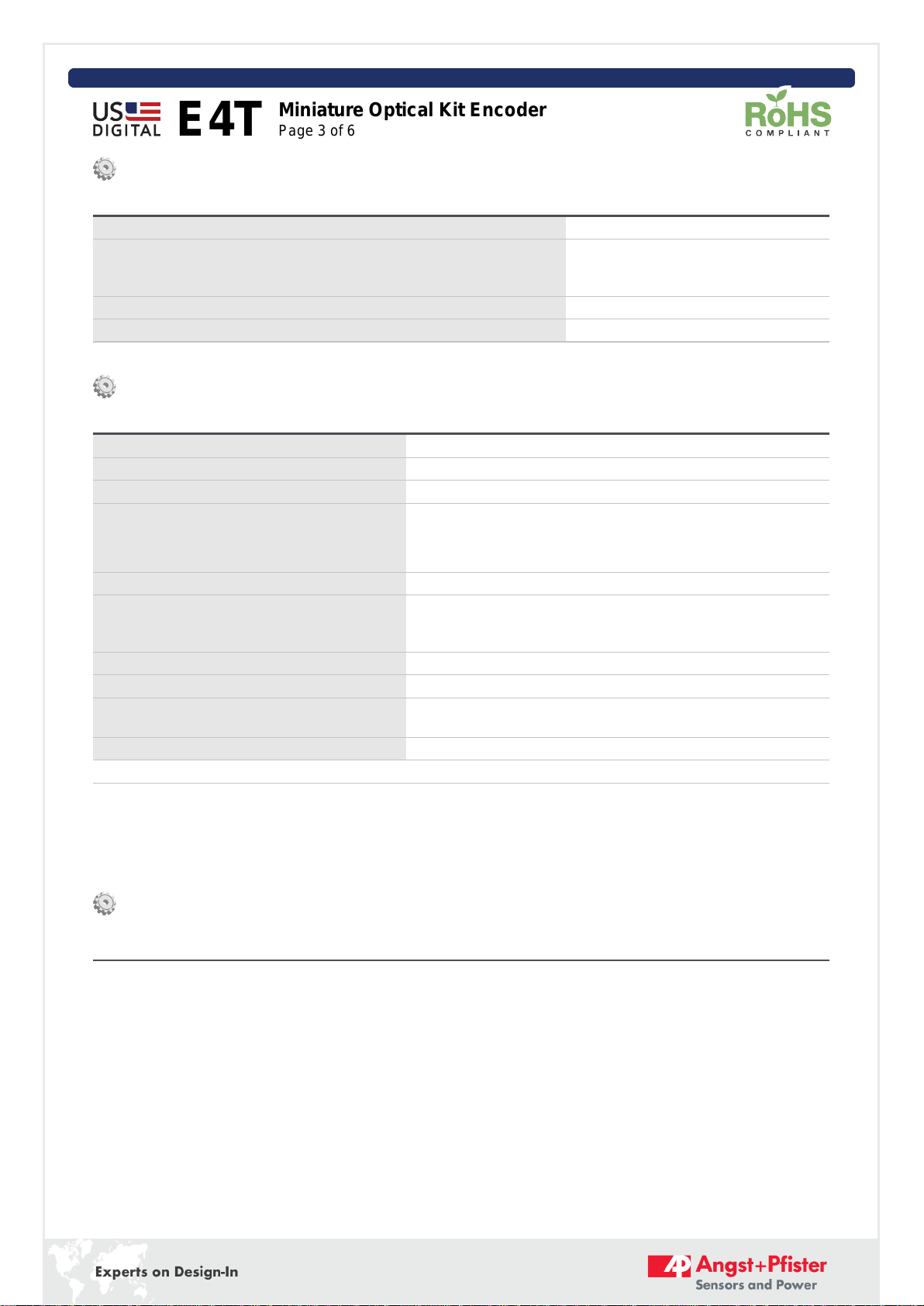
Mechanical
Parameter Value Units
Max. Shaft Axial Play ± .010 in.
Max. Shaft Runout (TIR) .002 in.
Max. Acceleration 250,000 rad/sec²
Maximum RPM (1)
e.x. CPR = 300, max. rpm = 20000
e.x. CPR = 200, max. rpm = 30000
minimum value of
(6000000/CPR)
and (60000)
RPM
Max. Codewheel Moment of Inertia 5.1 x 10^-7 oz-in-s²
Mounting Screw Size
Default (D-option base)
Metric (M-option base) #3-48 x 3/16"
M2.5, length 4mm
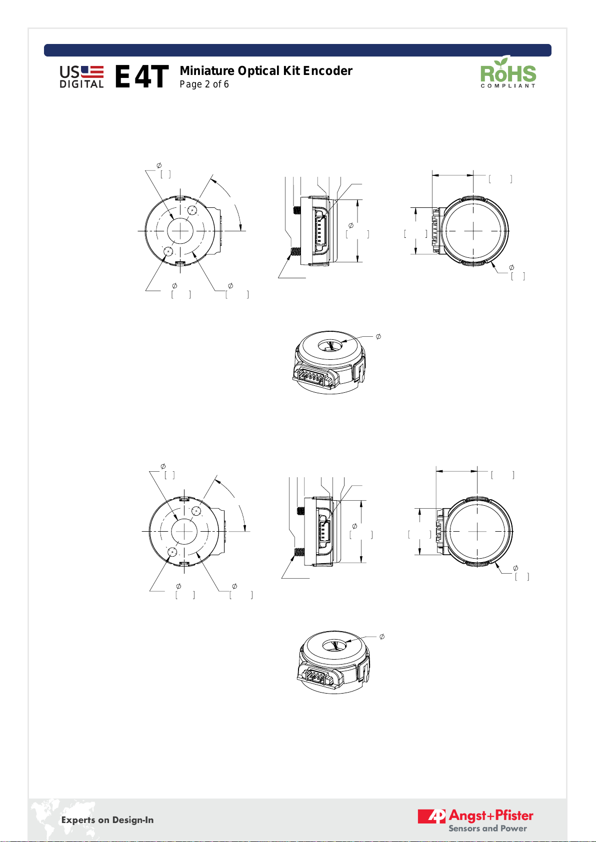
Screw Bolt Circle Diameter .586 ±.005 in.
Minimum Shaft Length (2) .275 in.
Maximum Shaft Length (2) .395 (D option) /
no limit (H option) in.
Mounting Screw Torque 2-3 in-lbs
Technical Bulletin TB1001 - Shaft and Bore Tolerances Download
(1) 60000 RPM is the maximum rpm due to mechanical considerations. The maximum RPM due to the module's 100kHz maximum
output frequency is (6000000/CPR).
(2) Including axial play.
Single-ended Electrical
Specifications Min. Typ. Max. Units Notes
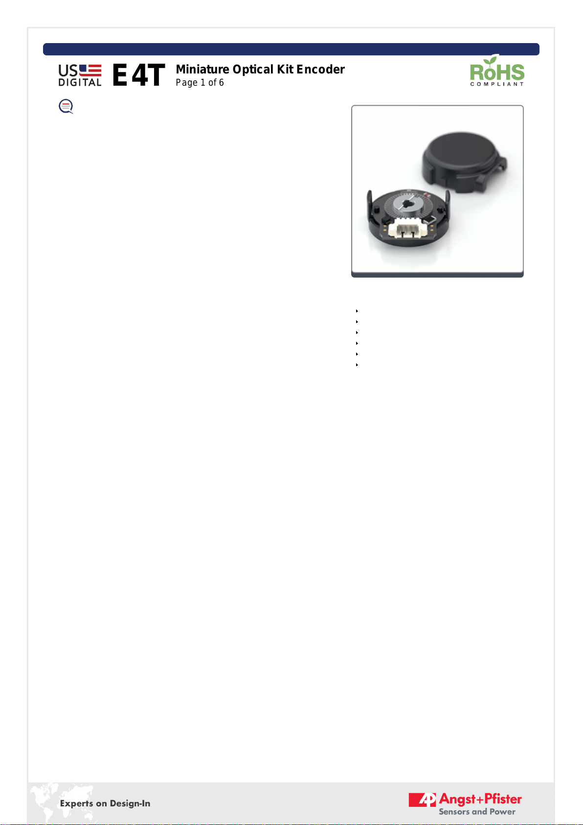
E4T Miniature Optical Kit Encoder
Page 3 of 6
Rev. 20181113012651