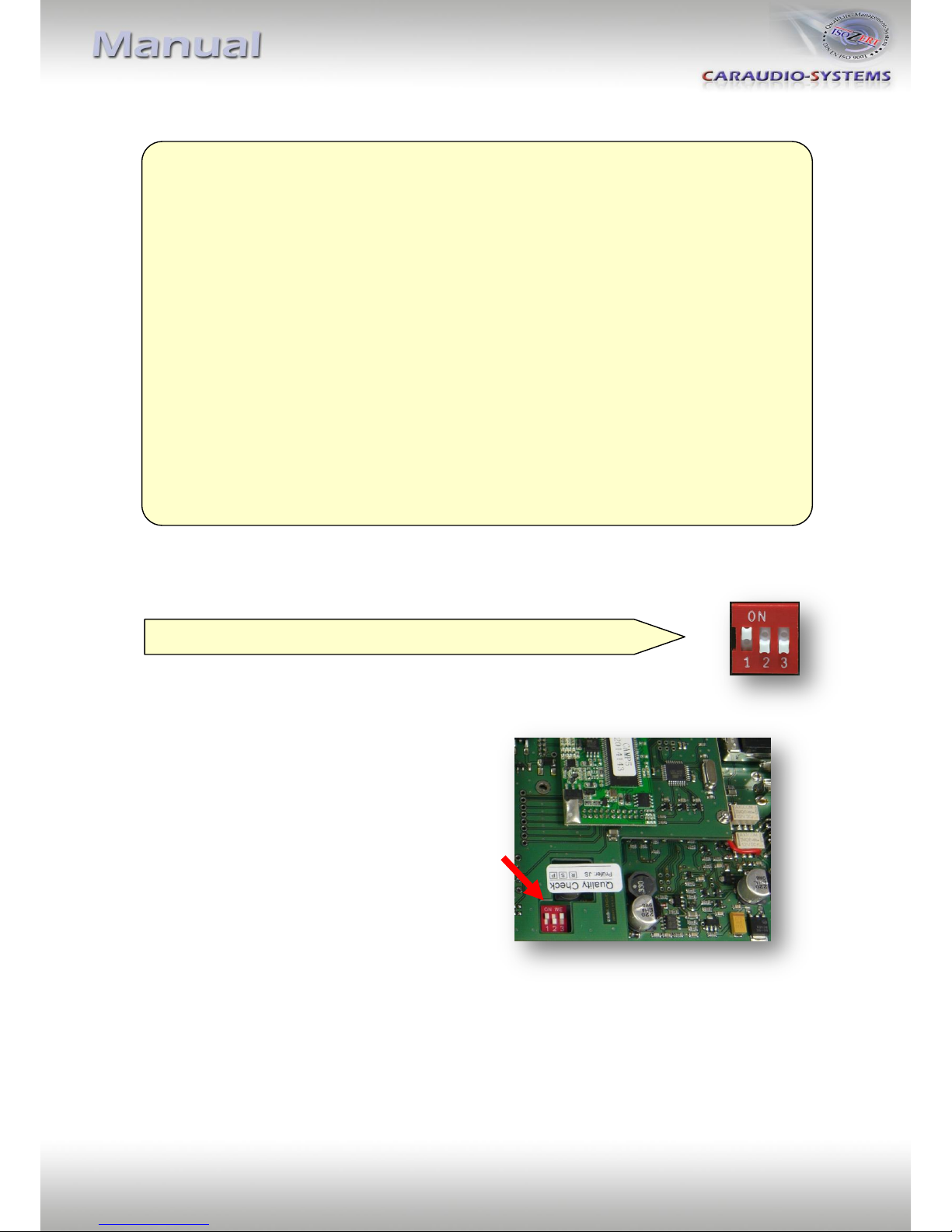
1.4.1. Automatic switching to rear-view camera
If an after-market rear-view camera shall be connected, in order for
the usbLOGiC to automatically switch to its camera input on engaged
reverse gear,
set dip2 = ON (up).
Note: With after-market cameras, automatic switching works only
from usbLOGiC mode. For automatic switching from OEM modes, it is necessary to code the
head-unit to rear-view camera per diagnosis computer or our optional available OBD-coder
OBD-MFD3-R-xx (Only possible on MFD3/RNS510 Version B with minimum software 1100).
If coding is done by diagnosis PC, code rear-view camera to "LOW" in controller 56 radio (not
in controller 19 - CAN gateway). After coding the vehicles needs to be locked to reach sleep
mode (30 seconds up to 66 minutes depending on vehicle).
Vehicles with OPS (optical parking system): If coding is done by diagnosis PC, code to rear-
view camera in controller 10 park assistant 2 (not in controller 19 - CAN gateway). After
coding the vehicles needs to be locked to reach sleep mode (30 seconds up to 66 minutes
depending on vehicle).
1.4.2. Deactivating usbLOGiC AV-input
If no peripheral AV-source shall be connected to the usbLOGiC, we
recommend to disable the AV-input, to avoid customers switching by
mistake to black/no picture of the AV-input. In order to disable the
AV-input of the usbLOGiC,
set dip1 = OFF (down).