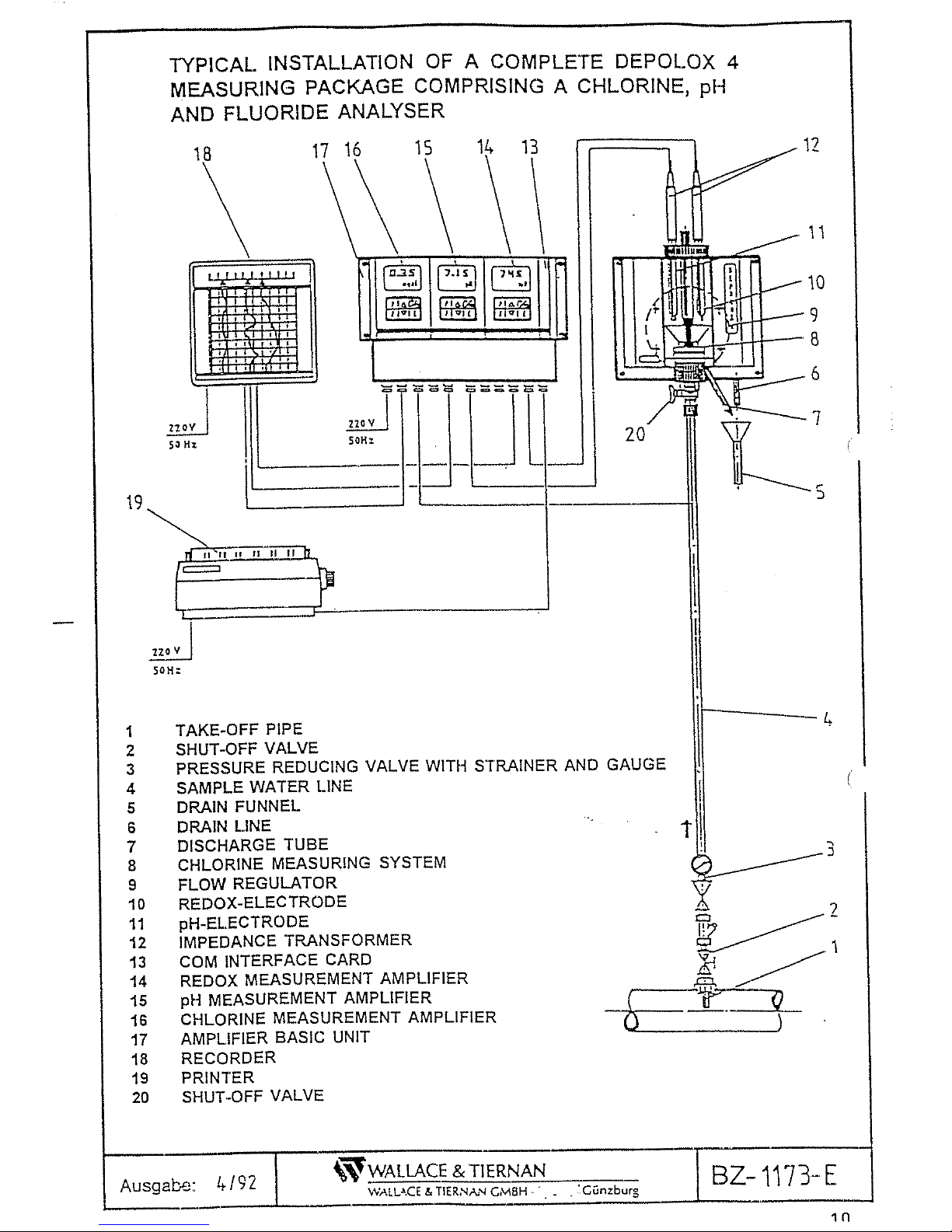
USF Wallace & Tiernan DEPOLOX 4 User manual

DEPOLOX 4®
BA - 40 004 E
MICROPROCESSOR BASED
ANALYSING AND CONTROL
SYSTEM FOR CHLORINE,
pH AND REDOX IN POTABLE
WATER AND SWIMMING POOLS
Wallace & Tiernan GmbH
D-89305 Günzburg
Telefon (08221 904-0
Telefax (08221 904-203
e-mail: [email protected]
www.wallace-tiernan.de

SALES ORDER NO. VA .............
NOTE:
The equipment has been made of first-class material and should perform satisfactorily
if properly operated and maintained. It is therefore most important that the instructions
be read, and understood, prior to installation, operation or maintenance.
Our guarantee is conditional upon the equipment being treated in accordance with this
instruction. To avoid errors please refer to the order number when corresponding with
us.
Not parts may be disassembled during the guarantee time without our permission.
At significant disturbances we recommend to call for our trained service personnel.
2

GUARANTEE
For a period of one year after shipment, we undertake to repair or replace free of
charge, f.o.b. Günzburg, all equipment or parts of our supply that have failed due to
defects in workmanship or material, provided that these parts have been used under
normal operating conditions.
Replaced parts shall become our property.
For parts not manufactured by us, especially electrical parts, our liability shall be limited
to the guarantee granted by our vendor. On the buyer’s request we will cede the
vendor’s guarantee to the buyer who shall then be solely responsible for the
implementation of the vendor’s guarantee.
Defects caused by normal wear, faulty operation, negligence or unsuitable process
materials, are excluded from our guarantee.
Also excluded are defects caused by unauthorised modifications or repairs performed
by the buyer or a third party.
The guarantee period will not be extended or renewed after a modification of the
equipment or the replacement of parts.
Defects not caused by our fault, for instance defects caused by faulty operation, use
of unsuitable chemicals or disobedience of the instruction manual, will be corrected by
us on the buyer’s request, at current prices and service charges.
Place of jurisdiction for all law suits regarding our supply or other legal matters shall
be the county court (Amtsgericht) of Günzburg or the district court (Landgericht) of
Memmingen, regardless of the extent of the claim.
3

CONTENTS
PAGE
1. GENERAL 8
2. DISINFECTANTS IN WATER - LIMIT VALUES 8
2.1 Chlorine (Cl2)8
2.2. Chlorine dioxide (ClO2)9
2.3 Ozone (O3)9
3. DEPOLOX 4 - INSTALLATION AND THEORY
OF OPERATION 9
3.1 Installation of a complete chlorine residual analyser
DEPOLOX 4 9-10
3.2 Theory of operation 11
3.3 Temperature compensation 12
4. INSTALLATION 12
4.1 Location of installation 12-13
4.2 Sample water take-off 13
4.3 Sample water drainage 14
5. STARTUP 14
5.1 Depolox 4 analyzer (pressureless type) 14
5.2 Depolox 4 analyzer (pressure type max. 1.5 bar) 15
5.3 Amplifier for chlorine measuring cell DEPOLOX 4 15-16
6. CALIBRATION OF THE DEPOLOX 4 AMPLIFIER 17
6.1 Calibration of range 17
6.2 Calibration of bias voltage 17
6.3 Zero calibration 18
6.4 Zero calibration with chlorine-free water 18
6.5 Zero calibration in case of a combination of 18
chlorine and ozone
6.6 Measured value calibration 19
6.7 Chemical analysing methods 19
7. MAINTENANCE 20
7.1 Zero point and measured value check 20
7.2 Servicing of the reference electrode 20
7.3 Change of grit 20
7.4 Strainer 21
7.5 Electrodes 21
7.6 Chemical and mechanical cleaning 21
7.7 Spares for maintenance 21
edition 06/1994
4

PAGE
8. TROUBLESHOOTING 22
9. pH-VALUE ANALYSER 23
9.1 pH probe with special cable 23
9.2 Startup of ph-value analyser 23-24
9.3 Maintenance of ph probe 25
9.4 pH-measurement using the phenol red method 25
9.5 Spare parts and chemicals for maintenance 26
10. REDOX ANALYSER 27
10.1 Redox probe with special cable 27
10.2 Start-Up 27-28
10.3 Maintenance of the redox probe 28
10.4 Spare parts and chemicals for maintenance 29
11. AMPLIFIER 30
11.1 Installation 30
11.1.1 Dimensions of basic unit, plug-in amplifiers 31
and COM interface card
11.2 Electrical installation 32
11.3 Front panel 33
11.4 Keypad 34
11.5 Parameter and function menus - set-up and 34
changing of settings
11.6 Basic amplifier setup 35
12. CHLORINE MEASURING AMPLIFIER 36
12.1 Paramter menus (standard Cl2amplifier) 36-37
12.2 Function menus (Cl2amplifier) 38
12.3 Paramter set-up during initial operation 38
12.3.1 Control element electric positioner or regulating valve 39
12.3.2 Control element metering pump, solenoid pump,
continuous output 40
12.4 Adjustment of feedback display 41
12.4.1 Potentiometer feedback (standard factory setting) 41
12.4.2 mA feedback 41
12.4.3 Adjustment of the feedback display 42
5

PAGE
13. pH MEASUREMENT AMPLIFIER 43
13.1 Parameter menu (standard pH amplifier) 43-44
13.2 Function menu (pH amplifier) 45
13.3 Set-up of control parameters for initial operation 46
(parameter menu)
13.3.1 For metering pumps (pulse duration or 46
continuous controller)
13.3.2 For solenoid pumps (pulse frequency controller) 46
13.3.3 For electric positioners and regulation values 46
(step rate controller)
14. REDOX MEASUREMENT AMPLIFIER 47
14.1 Parameter menu (standard Redox amplifier) 47-48
14.2 Function menu (Redox amplifier) 49
15. ERROR MESSAGES 50-52
16. INTEGRATED CONTROLLER (OPTION) 53
16.1 Three-step controller for servomotor 53
16.2 Metering pump controller (pulse duration controller) 54
16.3 Solenoid pump controller (pulse frequency controller) 55-56
16.4 Controller with continuous output 57
16.5 Control parameters and their influence on the control loop 58-61
17. ADAPTATION OF THE CHLORINE AMPLIFIER 62
17.1 Use of the adaptation 62
17.2 Preconditions for the adaptation 63
17.3 Adaptation menus 63
17.4 Sequence of the adaptation 64
17.5 Ending the adaptation sequence 65
17.5.1 Ending of the adaptation without error 65
17.5.2 Ending of the adaptation with error 66
17.6 Determination of the controller parameters using Tu and Ts 67
18. COM INTERFACE CARD 68
19. SERVICING AND REPAIR 68
20. TECHNICAL DATA 69
20.1 DEPOLOX 4 measuring cell 69
20.2 Basic unit for wall mounting 69
20.3 Chlorine residual amplifier 70
20.4 pH measuring amplifier 71
20.5 Redox measuring amplifier 72
6

PAGE
21. DRAWINGS AND WIRING DIAGRAMS
- BZ-1150/1-4/E
Residual analyser DEPOLOX 4 Abb. 2, Abb. 2A-E
- BZ-1150/5-5/E
Residual analyser DEPOLOX 4 pressurised cell Abb. 2F
- BZ-1150
Cellule de measure DEPOLOX 4 with bill of Material
- BZ-1141/E
Flow regulator, complete with bill of material
- BZ-1179/E
Sample water take off unit for DEPOLOX 4 with bill of material
- BZ-1165/E
DEPOLOX 4 sample water arrangement
- BZ-1166/E
Sample water arrangement incorporating sample water pump
with bill of material
- BZ-1167/E
Sample water arrangement incorporating sample water pump
with bill of material
- BZ-1184
Housing complete / U-93 743 with bill of material
- 30-E-7585 (sheet 1 - sheet 7)
Typical wiring diagrams for Cl2module
- 30-E-7578 sheet 1
Wiring diagram - amplifier for panel mounting
- 30-E-7578 sheet 2
Connection COM card
- U-95 590
Wall housing with bill of material
- U-95 649
Panel mounting housing with bill of material
- U-95 820
Panel mounting housing with bill of material
- U-95 822
Panel mounting housing with bill of material
- BZ-1145
Label to the amplifier
- Impendance converter BZ-1222-E and BZ-1223-E
- BZ-1245-E
Table of amplifiers
- WN-343
Connection parts for PVC-hose
7

1. GENERAL
The disinfection of potable water, swimming pool water and industrial water is usually
achieved by the addition of either chlorine, chlorine dioxide, sodium hypochlorite,
anorganic chlorine compounds or in combination with ozone.
It is very important to dose these disinfectants properly in order to achieve the correct
residual. An insufficient residual of the disinfectant may result in poor disinfection,
whereas an excessive residual may affect the taste of the water unfavourably or cause
corrosion in the water lines.
The DEPOLOX 4 residual analyser may be used for the continuous measurement of
disinfectant residuals such as chlorine, chlorine dioxide or ozone.
With additional equipment the dosage of these disinfectants may be controlled and
recorded.
The unit may also be used to check water which must not contain any disinfectants
(e.g. to check that no ozone is present after the water has passed through a
dechlorination filter).
2. DISINFECTANTS IN WATER - LIMIT VALUES
2.1 CHLORINE (Cl2)
According to current German regulations, potable water must not contain more than
0.3mg/l of effective chlorine. This amount may be increased temporarily up to 0.6mg/l
if required for sufficient disinfection.
A further requirement is that potable water (and water used by the food processing
industry) disinfected with chlorine shall contain at least 0.1 mg/l of free chlorine after
chlorination.
Processed swimming pool water (after flocculation, filtering and chlorination) is required
to contain 0.3...0.6 mg/l of free chlorine in every part of the swimming pool. The water
leaving the pool shall contain at least 0.3 mg/l of free and effective chlorine. If a
treatment with ozone is included in the process, the content of free chlorine in the water
shall be 0.2...0.5 mg/l.
NOTE!
The presence of chlorisocyanurates (chlorine stabilisers) will strongly impair the
measurement of chlorine residual. These chemicals, available in the form of
granules or pills, are not approved for use in swimming pool water and must not
be used in chlorine residual controlled systems.
8

2.2 CHLORINE DIOXIDE (ClO2)
Drinking water disinfected with chlorine dioxide is required to contain at least 0.05mg/l
of chlorine dioxide after treatment.
2.3 OZONE (O3)
The ozone residual in water depends on the type of process used and should there-
fore be determined during operation. To remove ozone completely from water, the water
can be passed through an activated carbon filter. Potable water must not contain any
ozone.
Swimming pool water is required to contain less than 0.05 mg/l of ozone before entering
the pool.
3. DEPOLOX 4 - INSTALLATION AND THEORY OF OPERATION
3.1 INSTALLATION OF A COMPLETE CHLORINE RESIDUAL
ANALYSER DEPOLOX 4 (see page 10)
Sample water flows through the take-off pipe (1), the shut-off valve (2), the pressure
reducing valve with strainer and gauge (3), the sample water line (4) and the flow
regulator with check valve (9) into the chlorine measuring system (8). The flow regulator
(9) is factory-adjusted and maintains a constant sample water flow through the measuring
cell. If the measuring cell is of the pressureless type, the sample water flows via the
drain line (6) into the drain funnel (5).
For additional measurement of pH and Redox, the appropriate electrodes can be plugged
into the body of the measuring cell. With these electrodes use is made of impedance
transformers for reducing the high internal resistance of the electrodes. All signal lines
are connected in the terminal block of the amplifier basic unit (17); the signals
are processed by microprocessor-based amplifier modules for chlorine (16), pH value
(15) and Redox (14).
Option: These amplifier modules can be provided with an integrated controller for direct
control of dosing pumps or control elements.
A recorder (18) or a visual display device may be connected to the volt-free analogue
amplifier output singal.
A digital COM interface card (13) allows the transmission of measured data, on/off
conditions and error messages to a printer (19).
9


3.2 THEORY OF OPERATION
(see BZ-1150/1-5/E, fig. 2, 2A-2F)
The DEPOLOX 4 measuring cell consists of a 3-electrode system with external
potentiostatic closed-loop control. The working electrode and the counter electrode
(BZ-1150/3-5/E, fig. 2D, item 1 and BZ-1150/2-5/E, fig. 2B, item 2) of the half-ring type
are made of a platinum alloy. A silver/silverchloride electrode serves as reference
electrode (BZ-1150/2-5/E, fig. 2B, item 3); the contact between reference electrode and
sample water is established by two membranes (BZ-1150/2-5/E, fig. 2B, item 7). The
reference electrode is mounted in PVC brackets and completely submerged in electrolyte
(BZ-1150/2-5/E, fig. 2A/B, item 60). The electrolyte container is transparent, thus
enabling a visual check to be made of the amount of electrolyte in the reservoir.
Replenishment of the electrolyte is possible without shutting down the measuring cell
system. A membrane in the plug of the electrolyte reservoir provides the necessary
equalization of pressure (BZ-1150/2-5/E, fig. 2A, item 17).
The measuring cell is connected to a digital measuring amplifier which maintains an
adjustable constant potential (Upot) between working and reference electrodes by means
of potentiostatic closed-loop control.
About 33 l/hr of the water to be analysed flows past this system of electrodes. The
current generated in the measuring cell is directly proportional to the concentration of
the oxidising agent in the sample water. This current is then passed to the
microprocessor-based electronic system for processing.
The surfaces of the electrodes are continuously cleaned by a special kind of cleaning
grit in the electrode cell. The transparent plexiglass body of the cell makes it possible
to observe the circulation of the grit in the cell.
An integrated flow regulator (BZ-1141/E) ensures a constant sample water flow of about
33 l/hr.
If desired, electrodes for pH-value and Redox measurement can be inserted into the
two holes (BZ-1150/2-5/E, fig. 2A, item 48) in the removable cover of the measuring
cell. This means that the DEPOLOX 4 measuring cell can be augmented with extra
measuring devices without any additional piping.
The following features of the DEPOLOX 4 ensure accurate, repeatable measured
data and reduce the frequency of zero point recalibration:
- potentiostatic control
- continuous hydromechanical electrode cleaning system
- regulated sample water flow.
11

3.3 TEMPERATURE COMPENSATION
If temperature fluctuations in the sample water are expected to exceed ± 10°C (e.g. in
hot-whirl-pool systems), temperature compensation is recommended.
In this case the required Pt 100 temperature sensor is incorporated in the measuring
cell block.
In the range between 5 and 50°C, temperature compensation of the measured chlorine
residual is performed automatically prior to display. During automatic operation of the
analyser, the matrix display unit of the amplifier shows the temperature of the sample
water. Further processing of the temperature signal is only possible via the digital COM
interface card.
4. INSTALLATION
4.1 LOCATION OF INSTALLATION
The DEPOLOX 4 unit should be protected from freezing temperatures, preferably
installed in a heated room. When installing the unit, it is very important to consider
both the chlorine contact time and mixing with the treated water.
POTABLE WATER
Adequate mixing of chlorine and water will be achieved if the distance between
the point of application and the sample water take-off point is at least 10 times
- preferably even 20 times or more - the diameter of the water line, e. g.
if the diameter of the water line is DN 300, the minimum distance will
be 300 mm x 10 = 3 m.
The contact time is the time that elapses between chlorine application and chlorine re-
sidual measurement. It is made up of both the flow time in the main line from the
point of application to the sample take-off point, and the flow time in the sample line
from the sample take-off point to the DEPOLOX 4. It is recommended that the sample
line be kept as short as possible.
If extended contact times, e.g. 5 to 15 minutes, are required, a contact tank can be
installed in the sample line directly before the measuring cell. It should be noted that
in this case a flow and residual control system must be used.
12

SWIMMING POOL WATER
The sample water take-off has to be installed in the return line to the pool. It
should be observed that the sample water has to be taken off before flocculation
agents are added and that the minimum pressure at the measuring cell must be
1.5 m head (0.15 bar).
These instructions are applicable to chlorine, chlorine dioxide and ozone.
The DEPOLOX 4 unit with amplifier should be mounted on a vertical wall, if possible
at eye level, by fastening it with the 4 bolts supplied in the 4 mounting holes in the
basic unit. Install the amplifier casing as close as possible to the measuring cell. The
connecting cable between the measuring cell and amplifier has a standard length of
1.5 m. If local conditions require it, use can be made of an extended cable (max. length:
50 m) via a plug socket. It is essential to use a screened cable. The signal line must
not be laid adjacent to any mains supply cable.
4.2 SAMPLE WATER TAKE-OFF
IMPORTANT!
Use a PVC hose (internal diameter 6 x 3) or a 6 mm PVC pipe for the sample
water line and locate the unit to minimize sample line length.
CAUTION: Copper pipes must not be used for the sample water line. Locate
the sample water take-off to ensure optimum mixing of disinfectant
and water, a continuous sample water flow without air bubbles as
well as a constant pH-value in the range between 4 and 8.
Depending on the local sample water pressure, one of the several sample water
take-off assemblies available should be selected. The pressure at the inlet of the
DEPOLOX 4 analyser must be within a 0.15 to 4.0 bar g range. In this pressure range,
a constant water flow of 33 l/h is provided irrespective of pressure fluctuations.
Water pressures of 4.0 to 40 bar g have to be reduced to 2.0 to 4.0 bar g by means
of a pressure reducing valve at the sample water take-off. If the required minimum
pressure of 0.15 bar is not available, a sample water pump has to be installed
(BZ-1179/E, BZ-1165/E, BZ-1166/E and BZ-1167/E).
13

4.3 SAMPLE WATER DRAINAGE
After leaving the measuring cell via the drain hose (page 10, item 6), the sample water
flows to waste via the supplied drain funnel and a 15 mm PVC pipe (pressureless
drainage).
If the DEPOLOX 4 analyser cell used is of the pressure-resistant type, the back pressure
in the sample water return line must not exceed a maximum of 1.5 bar; the sample
water inlet pressure must always be 0.5 bar higher than the back pressure (max. inlet
pressure: 2 bar).
5. STARTUP
5.1 DEPOLOX 4 ANALYZER (PRESSURELESS TYPE)
(BZ-1150/1-4/E, fig. 2A-2E)
1. Unscrew nut (fig. 2A, item 46).
2. Remove cover (fig. 2A, item 41).
3. Pull electrode assembly down and out of cell block.
4. Remove felt ring (transport protection of membrane).
5. Exchange plug against separately supplied plug fitted with membrane for
venting of the electrolyte reservoir.
6. Replace electrode assembly into cell block.
NOTE! Keying pin (fig. 2D, item 58) must snap into position.
7. Allow sample to flow by opening linlet valve.
8. Fill a half capful of grit (U-95 653) into the cell block.
9. Replace cover and tighten by nut.
NOTE! After a running-inperiod of about one hour measuring cell and amplifier
can be calibrated. A re-calibration should be made 24 hours after initial
calibration.
Air bubbles building up at the inner surface of the cell block and
preventing somewhat the rotation of the grit will disappear after a runing-
in period of about 24 to 48 hours.
14

5.2 DEPOLOX 4 ANALYZER (PRESSURE TYPE MAX 1.5 BAR)
(BZ-1150/5-5/E, fig. 2F)
1. Unscrew nut (fig. 2F, item 62).
2. Remove cover (fig. 2F, item 71).
3. Pull electrode assembly down and out of cell block.
4. Remove felt ring (transport protection of membrane).
5. Exchange plug against separately supplied plug fitted with membrane for
venting of the elctrolyte reservoir.
6. Replace electrode assembly into cell block.
NOTE! Keying pin (fig. 2D, item 54) must snap into position.
7. Allow sample to flow by opening inlet valve.
8. Fill a half capful of grit (U95 653) into the cell block.
9. Repalce cover and tighten by nut.
5.3 AMPLIFIER FOR CHLORINE MEASURING CELL DEPOLOX 4
After completion of the field the following initial startup procedure has to be followed:
1. Insert the amplifier module into the basic unit until it is firmly seated and
tighten fixing screws.
2. As soon as power is on, an automatic test of the amplifier is made, which
is signalled by the flashing of all display segments.
3. Check the factory-set amplifier setup against the following table. It does not
meet your requirements, reprogram the setup (refer to page 17, item 6). Press
the MANUAL/AUTOMATIC key scroll the parameter (P) and function (F)
menus by pressing keys "P" and "F" respectively. To switch from P to F
menu, press the MANUAL/AUTOMATIC key again (refer to page 34, item
11.5).
15

BASIC SETUP
Menu
Range RGE 0...1.00 mg/l F
Code 904 P
Option controller set value CSP 0.45 mg/l P
HI Alarm set 1.00 mg/l P
LO Alarm set 0.00 mg/l P
Limit time delay (Tv min.) 0.0 min P
Hysteresis 0.03 mg/l P
HI/LO Alarm set - - - (switched off) P
mA output signal 0...20 mA P
Selection cell DEPOLOX 4 P
Bias volts 250 mV P
Operation chlorination P
A detailed description of the amplifier functions is contained in the chapter "Amplifier"
(page 34, item 11.5).
16

6. CALIBRATION OF THE DEPOLOX 4 AMPLIFIER
IMPORTANT NOTE!
If the chlorination plant or the solution regulator is operated automatically, switch
from the automatic to manual operation mode prior to calibration or maintenance
of the DEPOLOX 4 amplifier. Press the MANUAL/AUTOMATIC key of the amplifier
- "Hd." will appear in the text display line. Activate the electric positioner of the
chlorinator by pressing the " " key.
As the water quality at individual locations may differ considerably, the calibration of
the DEPOLOX 4 analyser has to be carried out on site. As already mentioned, the
unit has to operate continuously for at least 24 hours before calibration can be
started.
After long duration shutdowns as well as after electrode cleaning or replacement,
the calibration has to be repeated and checked after 24 hours.
6.1 CALIBRATION OF RANGE
The factory calibration of the measuring range is 0 to 1.00 mg/l of free chlorine. Al-
ternative ranges (500 ppb, 1.0, 2.0, 5.0 or 99.9 mg/l) can be programmed prior to zero
calibration and DPD calibration.
1. Press the MANUAL/AUTOMATIC key of the amplifier menu display then press
key "F" repeatedly until "RGE" for range is displayed.
2. Press direction keys to select the range and enter the final value by pressing
key "E".
6.2 CALIBRATION OF BIAS VOLTAGE
The factory calibration of the bias voltage is 250 mV. For ozone measurement as well
as for water, sea water or brine water, the bias voltage must be changed to 300 mV.
1. Activate manual operation mode ("Hd.") and press key "P" repeatedly until
"CODE" is displayed.
2. Press direction keys to select access code "904" and enter this code (key
"E"). All the following parameters can now be changed in the P menu.
3. Press key "P" until "Upot" is displayed.
4. Select the desired bias voltage by pressing the direction keys and enter the
final value (key "E").
17

6.3 ZERO CALIBRATION
1. Activate manual operation mode and press key "F" until "ZRO mg/l" is
displayed.
2. Close shut-off valve (page 10, item 20) to shut off sample water flow and
wait for 3 minutes.
3. Press key "E" to enter the zero current.
4. Open shut-off valve.
5. Press the MANUAL/AUTOMATIC key to leave the F menu.
NOTE:
After the sample water flow is shut off, the indication of the amplifier with drop -
very fast initially then after about 1 minute more slowly.
During initial startup, a waiting period of 5 minutes must be observed even if the
digital display drops to 0.00 after a few seconds of flashes.
The potentiostatic measuring principle allows a 2 month interval between calibrations.
6.4 ZERO CALIBRATION WITH CHLORINE-FREE WATER
If chlorine-free water is available, it may be used for zero calibration. In some cases
(e.g. in waterworks) chlorine-free water for zero calibration may also be obtained by
turning off the chlorinator.
6.5 ZERO CALIBRATION IN CASE OF A COMBINATION OF
CHLORINE AND OZONE
If a combination of these two methods of treatment is used, the sample water for
checking and calibrating the zero point must be taken off after the activated carbon
filter of the ozonisation system. This means that there must be a second sample water
take-off after the activated carbon filter of the ozonisation system in addition to the
sample water take-off in the return line to the pool. Both sample water lines must be
coupled by means of a three-way ball valve before the measuring cell. In this way,
the sample water line can be used alternatively for measuring or zero-calibration
purposes.
18

6.6 MEASURED VALUE CALIBRATION
1. After completing the zero calibration, open shut-off valve (page 10, item 20)
and wait at least 2 minutes.
2. Activate manual operation mode and press key "F" until "DPD mg/l" is
displayed.
3. Take a sample from the drain hose and determine the content of free
chlorine, chlorine dioxide or ozone by means of the DPD method (colorimetre
or photometer).
4. Press direction keys until the determined value is displayed on the LED
display.
5. Enter this value into the amplifier memory by pressing key "E". The measuring
cell is now calibrated.
6. Leave the F menu and return to manual operation mode by pressing
MANUAL/AUTOMATIC key. Press this key again to switch to automatic
operation of the amplifier. The controller outputs (optional) are now activated.
6.7 CHEMICAL ANALYSING METHODS
The chemical determination of chlorine residual or other oxidising agents may be
performed conveniently by using either a colorimeter or a photometer. Both instruments
furnish precise values and are easy to handle. For chlorine and ozon measurements,
DPD tablets or DPD liquid have to be added to the water sample. The water colour is
subsequently checked against a colour chart or in the photometer (refer to the respective
instruction manuals).
To keep the measuring error as small as possible, compute the average of 3
consecutive samples.
19

7. MAINTENANCE
7.1 ZERO POINT AND MEASURED VALUE CHECK
After initial setup, the zero point and measured value should be checked periodically:
1. Daily check of measured value with DPD method.
2. Routine check of zero point (after 1 or 2 weeks).
3. "Check after 24 hours" following electrode cleaning or replacement and/or
following replacement of grit.
7.2 SERVICING OF THE REFERENCE ELECTRODE
The silver/silverchloride reference electrode (BZ-1150/2-5/E, item 3) is screwed into an
electrolyte receptacle filled with electrolyte gel. Replenish the electrolyte as soon as the
electrolyte level has dropped to the sample water level in the flow-through assembly
(electrolyte U-95 655). A visual check is necessary only every 2 months.
In cases where the DEPOLOX 4 is used for water having a temperature above 35°C
(Hot-Whirl-Pools) the electrolyte for the reference electrode has to be renewed every
4-6 months, for normal applications every 12 months.
7.3 CHANGE OF GRIT
As the grains of grit (U-95 653) used for continuous electrode cleaning wear down after
a while, the grit has to be replaced every 2 months. Proceed as follows:
1. Activate manual operation mode.
2. Close shut-off valve (page 10, fig. 1, item 20) to shut off sample water flow.
3. Open drain valve (page 10, fig. 1, item 7 and BZ-1141/E, fig. 3, item 19)
of the DEPOLOX 4 measuring cell by turning the knurled-head screw
counterclockwise.
4. When the cell body is empty, close drain valve.
5. Unscrew PVC nut (BZ-1150/2-5/E, fig. 2A, item 46) and remove cover
(BZ-1150/2-5/E page 95, fig. 2A, item 39).
6. Pull electrode assembly down and out of the cell block (BZ-1150/2-5/E, fig.
2A, item 41) and rinse measuring cell and cell block to remove grit particles.
7. Replace electrode assembly into cell block.
NOTE! The keying pin must snap into position.
8. Pour half a capful of grit into the cell block. (Use cap of spare grit glass).
9. Fasten cover (BZ-1150/2-5/E, fig. 2A, item 39) with nut (BZ-1150/2-5/E, fig.
2A, item 46).
10. Open shut-off valve (page 10, fig. 1, item 20).
20
Table of contents