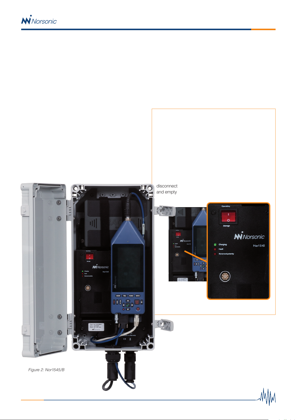
Norsonic Nor1545 Instruction Manual

Technical Note
Noise Monitoring Terminal
Nor1545 and Nor1545/B
www.norsonic.com
Innovative sound instrumentation
The Nor1545 noise-monitoring terminal is a robust and
efficient solution for outdoor noise monitoring. The cabinet is
normally supplied as a complete kit including Nor145 and out-
door microphone, combined with a variety of hardware options
to customize the system for the most demanding application.
It offers easy connectivity to NorCloud but may also be used
as a stand-alone unit. The Nor1545 is designed for semi- and
permanent installations.
The cabinet can be sold without instrument and outdoor
microphone when the customer already owns this equipment.
There are two versions of the cabinet;
Nor1545 and Nor1545/B.

2
Nor1545 / Nor1545B
Nor1545 – Weatherproof cabinet for Nor145
with mains input.
The cost-effective solution for fixed installations, where the
instruments internal battery will keep the system running
for 4-7 hour in case of a mains power failure, depending on
modem traffic and eventual use of microphone heating.
With an 12Vdc power connector installed (option 1), an
external power source can be used. This is a “fixed”
connection, meaning that there is no interrupt free switching
between 12V and mains. An alternative is also to connect
an external power source directly to the Nor145 power input
running the cable thru the cabinets cable gland mainly used
for the microphone cable.
The Nor145 is mounted inside the cabinet’s door using a
special tripod screw. This solution offers an excellent signal
strength on the LTE/4G modem as well as for the WiFi and
GPS. But if the cabinet is mounted in remote areas with
low signal strength, external antennas (option 4) will further
improve the connectivity.
The cabinet can be delivered with mast mounting brackets
(Option 2), but can also be attached directly to a wall with 4
simple screws.
Figure 1: Nor1545 Mains
Kit configurations
Nor1545/145-16: For fixed installations requiring microphone
heating. Weatherproof cabinet Nor1545 including; Nor145
with GPS, WiFi and 4G LTE, Nor1216 outdoor microphone
with Nor1227 microphone cartridge and Nor1408A 5 m
microphone cable. A Basic instrument subscription for
12 months is included (customer must have a NorCloud
Customer Account and cover the SIM card/data cost).
Filters, triggers and audio recording is available only via
NorCloud. Standalone SLM use of the Nor145 is there-
fore not possible without purchasing the upgrade Option;
Nor1545/145-SLM.
Nor1545/145-17: For semi-permanent installations where
a heated microphone system is not required. Same as
Nor1545/145-16 but with outdoor microphone Nor1217
instead of Nor1216.
Options;
Nor1545/145-SLM: Upgrade kit including Nor145 option 3,
4 and 11 for SLM use of instrument
Option 1: External 12Vdc plug for connection of an external
power source (battery / solar panel solution)
Option 2: Mast mounting brackets
Option 3: Set of table top feet
Option 4: Set with two external antennas for full diversity

3
Nor1545 / Nor1545B
Figure 3: Status LEDs and Operating swich
Figure 2: Nor1545/B
Nor1545/B – Weatherproof cabinet for
Nor145 - advanced applications
This cabinet supports the use of multiple power sources
simultaneously, Noise Compass (Nor1297), weather station
and digital I/O.
The cabinet can be powered from mains, 12Vdc external
power from a battery or a solar panel directly and be fitted
with an internal Tracer 22Ah LiPo battery. Or, a combination of
these power sources for full redundancy.
The Tracer battery, Nor344 - not included, will keep the system
running for typically three days. The battery is charged when
mains is connected, this also applies to the Nor145s own
battery. A solar panel or other 12vdc power source may also
be connected directly to the 12Vdc input terminal block, or the
7 pin Binder connector placed in the bottom of the cabinet
if option 1 is installed (Pin 1 is plus and pin 2 is negative/
ground).
Status LED and Operating switch
The green CHARGING LED is turned on when the internal
Tracer battery is charging.
The red FAULT LED is turned on if the temperature is
outside the allowed charge limit 0-40 °C.
The REVERSED POLARITY LED is turned on if the
external 12 V/Solar panel is connected with reversed
polarity.
For storage, turn the OPERATING switch to 0 and then
disconnect the Tracer battery. If not, a small current will flow
and empty the battery. This can damage the battery.
Two configurable inputs actions and one digital output are also
available.
The Nor145 is mounted on a quick release tripod mount. This
solution offers an excellent signal strength on the LTE/4G
modem as well as for the WiFi and GPS. But if the cabinet
is mounted in remote areas with low signal strength, external
antennas (option 4) will further improve the connectivity.
The cabinet can be delivered with mast mounting brackets
(Option 2), but can also be attached directly to a wall with
4 simple screws.

4
Nor1545 / Nor1545B
Weather station
Digital I/O
12V DC input
Nor1297
Figure 4: Connection terminals
Connection of mains power, 12V, solar panel and
auxiliary equipment
There is a built-in interrupt free switching between available
power sources. The switching between the instrument’s own
battery, the optional internal Tracer battery, external 12Vdc or
solar panel and mains is uninterrupted and is performed with
the following priority sequence;
Solar panel > Mains > External 12Vdc > Internal Tracer battery
> Nor145’s own battery.
A “power alarm” is sent to NorCloud if mains or external 12Vdc
disappears, and a “battery alarm” is registered when the
Instrument starts to operate from its own internal battery.
I.E. when there is no external power available.
To access the 12Vdc input, Noise compass connector, weather
station terminal block and Digital I/O, remove the cover shown
in figure 4. The cover is mounted with two Torx # 10 screws.
Mains.
Mains is connected to a 4-pin Binder connector, mounted in
the bottom of the cabinet. Power consumption is max 60W.
Pin 1 is L, pin 2 is N and pin 4 is GND.
Internal Battery
The internal battery to be used in the Nor1545/B cabinet is the
Tracer 22Ah-12V Lithium Polymer battery pack. The battery
is normally not a part of the delivery and should be sourced
locally.
Caution! The Tracer battery cannot be sent as airfreight
or brought onto an air plane as hand luggage. IATA has
set a maximum limit for energy level in lithium batteries to
100Wh. The tracer battery is 264Wh. This applies also if
the battery is discharged to a level below 100Wh.
12VDC
External 12Vdc from a car battery or similar must be connecte
to the 12Vdc connector terminal located to the right in figure 4,
or if option 1 is installed via the 7 pin Binder connector. Voltage
input range is 9-28Vdc.
Solar Panel
The solar panel must be connected to the 12Vdc connector
terminal located to the right in figure 4, or if option 1 is installed
via the 7 pin Binder connector. A built-in solar panel controller
will charge the internal batteries with up to 3 ampere. Any solar
panel with an idle voltage of less than 30V can be used.
The cable for the solar panel or the external 12Vdc can be run
through the microphone cable gland located in the bottom of
the cabinet. The external 7 pins Binder connector (Option 1)
could be more suitable if the cabinet is used for mobile
applications.
Caution! Only one external 12Vdc source must be
connected. You must either connect the external DC
source to the 12Vdc input terminal in figure 4 or to the
Binder 12V connector in figure 2 (if applicable). I.E. To
simultaneously use both a solar panel and an external
battery is not possible.

5
Nor1545 / Nor1545B
Nor1297 – Noise compass
Connect the Norsonic Noise Compass to the LAN plug as
shown in figure 4. This LAN connector has a passive power
over LAN feature supplying the Noise Compass with a 12Vdc.
Caution! No other LAN equipment than the Noise
Compass must be connected to this connector. If Nor145
needs to be connected to a LAN network, the LAN
connector located on the Nor145 itself must be used. The
use or a router is required when a Noise Compass shall
be used together with the LAN network.
Weather Station
Nor1545/B supports the weather station Thies Clima US
model 4.920x.00.000. The weather station can be connected
to the terminal block as shown in the left picture in figure 5.
If option 6 is installed it can also be connected using a 8 pin
Lemo contact that you then will find just above the connector
panel, shown to the right in figure 4.
The Thies Clima US (figure 6) is equipped with a heating
element of 24 ohm, which is needed then operating where
temperatures are below 0 °C. This heating can be switched
on/off in NorCloud or using the Thies control software. By
default factory settings the Thies Clima is set to turn on heating
at +5 °C . To get full effect of the heater, the weather station
must be powered with 24Vdc. With option 5 installed a 24Vdc
power output is supplied, but only if powered on mains.
It is recommended to power the weather station with 12Vdc to
save power and to enable battery/solar panel operation when-
ever heating is not required. The cable to the weather station
must be configured accordingly. Either connect the power to
the 12Vdc on the terminal block / Lemo connector, or to the
24Vdc. Ref. table 1 and 2 for detailed information.
The cable Nor4638, should be used when the terminal block
is used to connect the weather station. When using a Lemo
connector (option 6), the cable Nor4639-12V must be ordered
for 12Vdc output, and Nor4639-24V for a 24Vdc output.
When the weather station is connected to a 12V power supply
and the heater is turned on, only a ¼ of the heating power is
available (I.E: 6 Watt).
Digital output
Nor1545/B has one digital output available on the connection
block shown in figure 4. The digital output is configured from
NorCloud. Typical application is to turn on an alarm lamp or
similar in case of an event. The maximum current the digital
output can supply is 30mA. Output voltage for logical “1”
is 3,3V. The digital output is referred to DO-1 in the Nor145
instruction manual. A Solid-state relay or similar should be
added to isolate the Nor1545 / Nor145 from the auxiliary
equipment.
1
2
4
6
8
3
5
7
Figure 5: Weather station connection. Terminal block (left), and Lemo connector (option 1 – right)
Figure 6: Thies weather station

6
Nor1545 / Nor1545B
Table 1: Connection of weather station to connector block
Table 2: Connection of weather station to Lemo connector
Pin no. Connector block naming Comment
1 Yellow, TXD+, RXD+ (HD) RS422
2 Green, TXD-, RXD- (HD) RS422
3 Brown, RXD+(full duplex) RS422
4White, RXD-(full duplex) RS422
5 Red, (12V, ¼ heating power) 12 V power to weather station. Use this pin if no heating is needed. If heating
is turned on, only ¼ of the heating power (=6W) will be dissipated due to the
12V power.
Note. Either pin 5 or 6 must be connected. Not both !
6 Red, (24 V Full heating) 24 V power to weather station. Use this pin if heating is required.
Note. This requires that option 5, 24VDc supply is installed (option 5).
Note. This supply works only if the Nor1545/B is powered from mains. If bat-
tery operation is required, connect to pin 5 instead.
Note. Either pin 5 or 6 must be connected. Not both !
7 Blue, - 24 V (GNB) Ground
8Grey, GND Ground
Pin no. Naming in Thies instruction manual Comment
1 Brown, RXD+(full duplex) RS422
2White, RXD-(full duplex) RS422
3 Red, (12V, ¼ heating power) 12 V power to weather station. Use this pin if no heating is needed. If heat-
ing is turned on, only ¼ of the heating power (=6W) will be dissipated due to
the 12V power.
Note. Either pin 3 or 4 must be connected. Not both !
4Red, (24V full Heating,) 24 V power to weather station. Use this pin if heating is required. Note. This
requires that option 5, 24VDc supply is installed (option 5).
Note. This supply works only if the Nor1545 is powered from mains. If bat-
tery operation is required, connect to pin 3 instead.
Note. Either pin 3 or 4 must be connected. Not both !
5ReGrey, GND Ground
6Blue, (GND) Ground
7 Yellow, TXD+, RXD+ (HD) RS422
8 Green, TXD-, RXD- (HD) RS422

7
Nor1545 / Nor1545B
Digital input
Nor1545/B has two digital inputs available on the connection
block shown in figure 4. The digital input is configured from
NorCloud. Typical application is to connect a digital signal,
such as a switch, to indicate an alarm or event. The digital
inputs are 3.3V CMOS signals. The voltage level shall be
within 0 to +5V. Voltage range 0 to 0.6V will be accepted as
logical “0” and voltages above 2.5 V will be accepted as logic
“1”. The input impedance is 100k ohm connected to the 3.3v
supply. An open input will therefore be treated as logic “1”.
The 3.3V and the GND on the digital I/O connector block is
for the digital I/O purpose only. The 3.3V is limited to supply
maximum 100mA.
12VDC supply to auxiliary equipment
The 12V on the connector block for the weather station may
be used to supply auxiliary equipment, such as an IP camera.
However, great care should be taken not to overload the power
supply, causing it to shut off. The total current available to sup-
ply all the connected electronics (Nor145, Weather station,
battery charging of the internal battery, Noise compass etc)
is 3 ampere. The charging of the battery is automatically ad-
justed to use the remaining current when all connected equip-
ment has been supplied. How much power that is available for
the auxiliary equipment depends on power consumptions of
the connected equipment. Cf table 3.
A recommended guideline is to connect equipment that
draws maximum 5W.
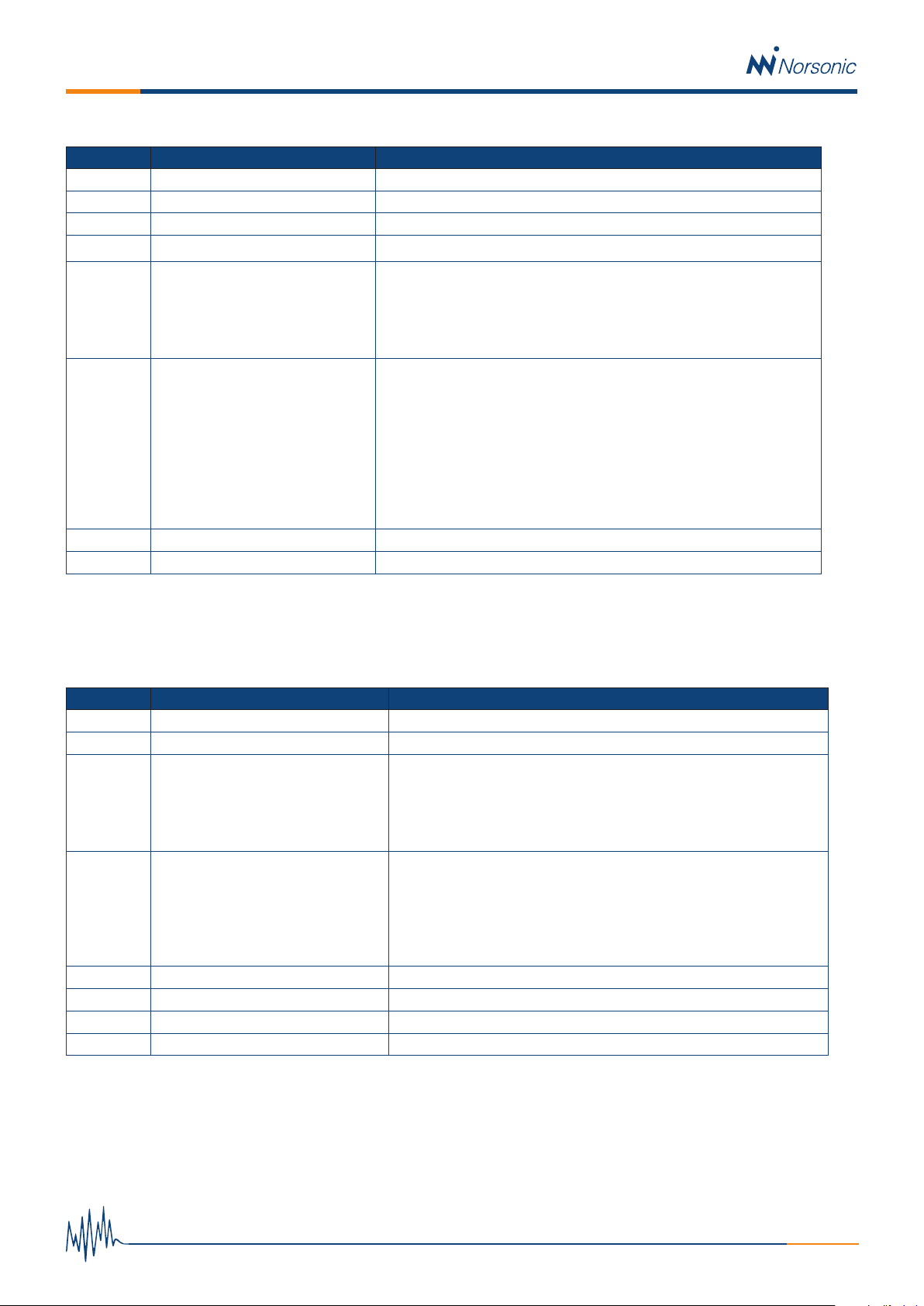
Table 3 Maximum power consumption @12V
Nor145 Weather station Nor1297
Available for
Battery charge/
Auxiliary equipment
0,5 Amp
6W Max
0,6 amp
7, 2W @ 12V
with
heater on)
0,15 Amp
(1,8W)
1,75Amp
Connecting IP camera
An IP camera should preferable be connected to the Nor145’s
LAN socket. But if a Noise Compass is not connected, it
could also be connected to the LAN connector for the Noise
Compass and powered by the connector’s passive 12Vdc
power over LAN.
NB! Please verify the IP cameras power consumption and
voltage rating before connecting any equipment to this
plug.
A router will be required if, at the same time, a Noise
Compass shall be connected. In this case, connect the router
to the Nor145’s LAN connector and connect the IP camera
and the cable coming from the Nor1545 to the router.
In this configuration the IP camera can be powered by the
12Vdc power supply from the weather stations terminal block,
given that this is a suitable power level. If not, a separate
power supply must be used.
Connectivity.
Nor145 comes with an internal LTE 4G modem. The antenna
in the Nor145 offers good connection in most environments.
But in areas with weak signal strength, the use of two exter-
nal LTE antennas (option 4) is recommended for improved
signal strength and diversity. Connect the external antennas to
the two antenna interfaces on the Nor145 and select the use
of external antenna in the instrument’s setup menu (‘setup ->
communication -> cellular’).
Cabled LAN network is also supported. A simple LAN connec-
tion shall be connected directly to the Nor145. A router must
be used when a cabled LAN network is used in combination
with Noise Compass and/or IP camera. The LAN socket in
the cabinet is reserved for the Noise Compass as it got a 12V
power over LAN feature.

Distributor:
TN 1545 Ed1Rv0En 1019
Nor1545 / Nor1545B
Norsonic AS reserves the right to change specifications and accessories without notice.
Kit configurations
Nor1545 / B-145-16: For advanced, fixed installations requiring
microphone heating, with multiple solutions for power supply.
Weatherproof cabinet Nor1545/B including; Nor145 with GPS,
WiFi and 4G LTE, Nor1216 outdoor microphone with Nor1227
microphone cartridge and Nor1408A 5m microphone cable.
A Basic instrument subscription for 12month is included
(customer must have a NorCloud Customer Account and cover
the SIM card/data cost). Filters, triggers and audio recording
is available only via NorCloud. Standalone SLM use of the
Nor145 is therefore not possible without purchasing an
upgrade Option; Nor1545/145-SLM. This cabinet support
Noise Compass (Nor1297) and the weather station Thies
Clima US (pn 4.920x.00.000). The internal Tracer battery is
not included!
Nor1545 / B-145-17: For advanced, semi-permanent instal-
lations not requiring microphone heating, with multiple
solutions for power supply. Same as Nor1545/B-145-16 but
with outdoor microphone Nor1217 instead of Nor1216.
Options:
Nor1545/145-SLM: Upgrade kit including Nor145 option 3,
4 and 11 for SLM use of instrument
Option 1: External 12V dc plug for connection of an external
power source (battery / solar panel solution)
Option 2: Mast mounting brackets
Option 3: Set of table top feet
Option 4: Set of two external antennas for full diversity
Option 5: 24Vdc heating for weather station (only when
connected to mains).
Option 6: Lemo connector for weather station.
Option 5 and 6 for Nor1545/B only.
Technical data
Cabinet construction / material: High pressure molded fiberglass-reinforced
Weight Nor1545 (including Nor145): 3,3 Kg
Nor1545/B (including internal battery and Nor145): 5,1 kg
Option 2, set of mast mounting brackets: 650 g
Option 3, set of table top feet: 950 g
Size (WxDxH): 200x132x400 mm
Enclosure class: IP66 (IP 67 with extra sealant added in the cable gland)
Flammability rating (enclosure): UL746C 5 inch flame test.
Operational temperature: -20 to 50 °C
Recommended storage temperature: 10 to 30 °C
Temperature range for battery charge: 0 to 40 °C
Wall mounting: 4x M5 or M6 screws in a 180 x 380 mm pattern
Electrical:
Mains: 88 to 264 Vac (47-63Hz) / 125 – 373 Vdc
12V input: 9-28Vdc
Power consumption (maximum rating): 48W
This manual suits for next models
1
Table of contents
Other Norsonic Measuring Instrument manuals

Norsonic
Norsonic nor103 User manual

Norsonic
Norsonic nor118 User manual

Norsonic
Norsonic nor145 User manual

Norsonic
Norsonic NOR150 User manual

Norsonic
Norsonic nor103 User manual

Norsonic
Norsonic NOR150 User manual

Norsonic
Norsonic nor140 User manual

Norsonic
Norsonic nor121 User manual

Norsonic
Norsonic 140 User manual

Norsonic
Norsonic nor140 Operating and maintenance manual