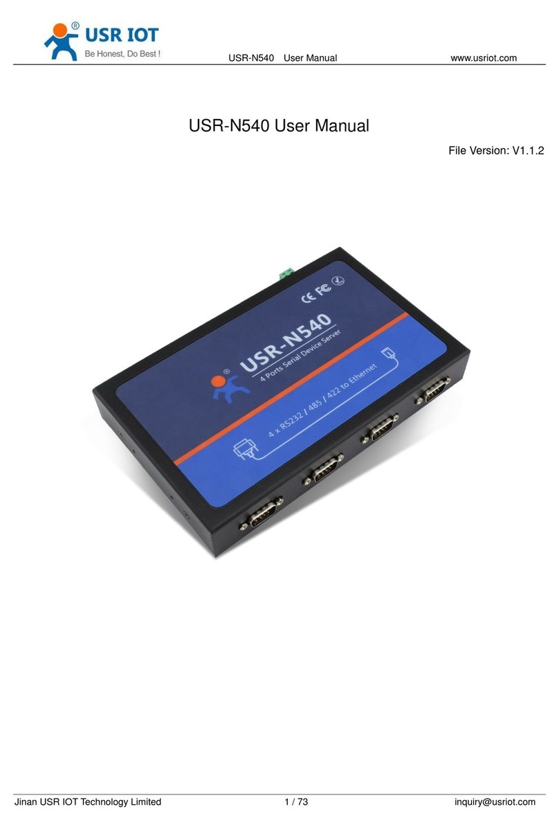
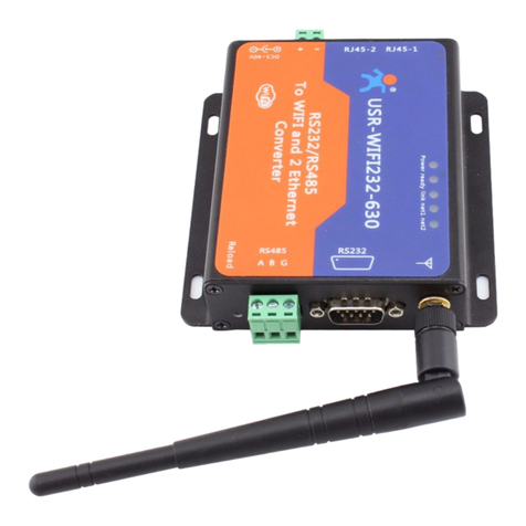
USR IOT USR-N5X0 Series User manual

USR-DR404 AT 指令集
1
USR-N5X0 Series
User Manual V1.0.0
Serial to Ethernet Device Server
Build a Smarter IoT world, Your Trustworthy Partner
USR-N510,USR-N520,USR-N540,USR-N580

User Manual
Your TrustWorthy Industrial IoT Partner www.pusr.com
1
1. Introduction ....................................................................................................... 5
1.1. Overview .................................................................................................... 5
1.2. Features .....................................................................................................5
2. Get started ........................................................................................................7
2.1. Installation ................................................................................................... 7
2.1.1. Wall mounting .......................................................................................... 7
2.1.2. DIN-Rail mounting ...................................................................................... 7
2.2. Serial port ................................................................................................... 9
2.3. Power supply ............................................................................................... 11
2.4. Ethernet RJ45 interface ..................................................................................... 11
2.5. LED indicators .............................................................................................. 12
2.6. Factory default settings ..................................................................................... 12
2.7. Quick test .................................................................................................. 12
2.7.1. Download the software .................................................................................13
2.7.2. Hardware connection .................................................................................. 13
2.7.3. Network configuration(Step1) ........................................................................ 14
2.7.4. Data transmission test(Step2 and 3) .................................................................. 15
2.8. Reload factory settings button ............................................................................... 16
2.9. Technical support and assistance ............................................................................ 16
3. Configuration and parameter details ................................................................................18
3.1. Web interface(V1 version) .................................................................................... 18
3.1.1. Status .................................................................................................18
3.1.2. IP settings .............................................................................................20
3.1.3. Serial port settings .....................................................................................21
3.1.4. Websocket server ..................................................................................... 23
3.1.5. Miscellaneous settings ................................................................................. 24
3.1.6. Management ..........................................................................................25
Reboot .............................................................................................26
Restore factory defaults ............................................................................. 26
Firmware upgrade .................................................................................. 26
3.2. Web interface(V2 version) ................................................................................... 27
3.2.1. Status ................................................................................................ 27
3.2.2. IP settings ............................................................................................ 29
3.2.3. Serial port settings .................................................................................... 30
3.2.4. Websocket server ..................................................................................... 32
3.2.5. MQTT gateway ........................................................................................33
Content

User Manual
Your TrustWorthy Industrial IoT Partner www.pusr.com
2
3.2.6. Edge computing ...................................................................................... 36
3.2.7. Cloud service ......................................................................................... 39
3.2.8. System setup ......................................................................................... 39
Restart ............................................................................................. 40
Restore factory defaults ............................................................................. 40
Firmware upgrade .................................................................................. 40
3.3. Configuration software ...................................................................................... 41
3.3.1. Discovering your device server ..........................................................................41
3.3.2. Network setting ....................................................................................... 41
3.3.3. Reboot the device ..................................................................................... 42
3.3.4. Restore to factory default settings ...................................................................... 42
3.3.5. Open web server ......................................................................................43
3.4. AT command ............................................................................................... 43
4. Operation modes ................................................................................................. 44
4.1. TCP Server ................................................................................................. 44
4.1.1. Properties ............................................................................................. 44
4.1.2. Multihost setting .......................................................................................46
4.2. TCP Client ..................................................................................................47
4.2.1. Properties .............................................................................................47
4.2.2. SSL/TLS .............................................................................................. 48
4.2.3. transient connection ...................................................................................48
4.3. UDP Server ................................................................................................ 49
4.3.1. Properties .............................................................................................49
4.4. UDP Client ................................................................................................. 51
4.4.1. Properties .............................................................................................51
4.4.2. UDP multicast .........................................................................................52
4.5. HTTP Client ................................................................................................ 54
4.5.1. Properties .............................................................................................54
4.5.2. HTTPS ............................................................................................... 55
4.6. Websocket server ...........................................................................................55
5. Virtual COM port ................................................................................................. 58
5.1. TCP Server Application with Virtual COM ...................................................................... 59
5.2. TCP Client Application with Virtual COM ...................................................................... 62
5.3. Enable RFC2217 through Virtual COM ......................................................................... 64
5.3.1. PUSR customized RFC2217 protocol ..................................................................... 66
6. Modbus TCP/RTU gateway ........................................................................................ 67
6.1. Ethernet masters with serial slaves ............................................................................67
6.2. Serial master with Ethernet slave ............................................................................. 68
6.3. Serial master with serial slaves ............................................................................... 70
6.4. Serial master via virtual COM with serial slaves ................................................................ 71

User Manual
Your TrustWorthy Industrial IoT Partner www.pusr.com
3
6.5. Modbus poll with serial heartbeat packet ......................................................................74
7. Advanced features ................................................................................................ 76
7.1. Packing mechanism ......................................................................................... 76
7.2. Heartbeat packet ........................................................................................... 76
7.3. Registration packet ..........................................................................................77
7.4. Socket B ................................................................................................... 78
7.5. Rs485 bus detection ........................................................................................ 79
7.6. Serial Printer setting .........................................................................................79
7.7. NTP ........................................................................................................82
7.8. SNMP ......................................................................................................83
8. MQTT gateway ................................................................................................... 85
8.1. Basic settings ............................................................................................... 85
8.2. Publishing a message ....................................................................................... 88
8.2.1. MQTT.fx tool introduction .............................................................................. 88
8.2.2. Transparent transmission .............................................................................. 90
8.2.3. Topic distribution ..................................................................................... 92
8.2.4. Custom mode ........................................................................................ 94
8.3. Subscribe to a topic .........................................................................................96
9. Edge computing ..................................................................................................98
9.1. Add modbus slave device .................................................................................... 98
9.2. Add modbus data points .....................................................................................99
9.2.1. Register type and offset ................................................................................ 99
9.2.2. Raw data types and byte order ........................................................................ 100
9.2.3. Data points configuration ............................................................................. 100
9.3. Export and import configuration .............................................................................102
9.4. Data report ................................................................................................104
9.4.1. Communication channel .............................................................................. 104
9.4.2. Report method .......................................................................................104
9.4.3. Payload-Json template ................................................................................105
9.4.4. Test .................................................................................................108
9.5. Data query ................................................................................................ 110
9.5.1. Json .................................................................................................110
9.5.2. Modbus slave address and register mapping ............................................................111
9.5.3. Modbus TCP .........................................................................................112
9.5.4. Modbus RTU .........................................................................................114
10. AWS IoT service ................................................................................................ 116
11. PUSR cloud service ..............................................................................................116
12. Warranty ....................................................................................................... 116
13. Contact Us ..................................................................................................... 116
14. Disclaimer ..................................................................................................... 116
15. Revision History .................................................................................................116

User Manual
Your TrustWorthy Industrial IoT Partner www.pusr.com
4

User Manual
Your TrustWorthy Industrial IoT Partner www.pusr.com
5
1. Introduction
1.1. Overview
The USR-N5X0 Series are network-based serial device servers that connect RS-232/422/485 serial devices, such as PLC, meters,
sensors, weigh scale, barcode scanner, card reader and serial printer directly to a TCP/IP network. Data coming from the Ethernet
port is sent to the designated RS-232/RS-422/RS-485 port, and data received from RS-232/RS-422/RS-485 port is sent to the
Ethernet port, allowing bi-directional communication.
In the computer-aided manufacturing or industrial automation areas, field devices can directly connect to an Ethernet network via the
USR-N5X0 modbus gateway. In normal PCs or laptops, a virtual COM port can be created using our virtual COM software to fetch
serial data from USR-N5X0 remotely over Ethernet. This extends the traditional COM ports of a PC,with access over a TCP/IP network.
Through networking, you can control and monitor remote serial devices over the LAN or even over the Internet.
The specific models of this series of industrial serial server are as follows. Please contact our sales for more information.
Table 1 USR-N5X0 series models
Model name
Description
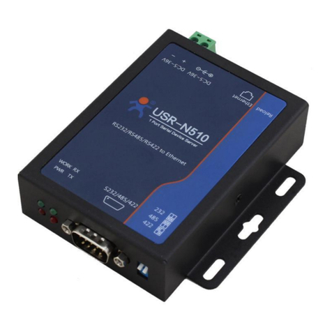
USR-N510
1 RS232/485/422 to Ethernet device server
USR-N510-4
1 RS485 to Ethernet device server
USR-N520
2 RS232/485/422 to Ethernet device server
USR-N520-6
2 RS232/485 to Ethernet device server
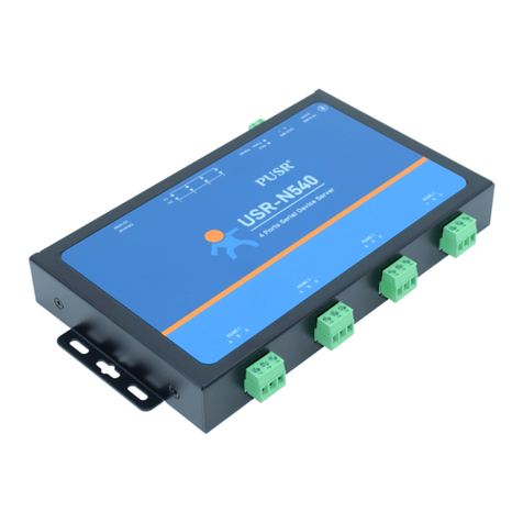
USR-N540
4 RS232/485/422 to Ethernet device server
USR-N540-4
4 RS485 to Ethernet device server
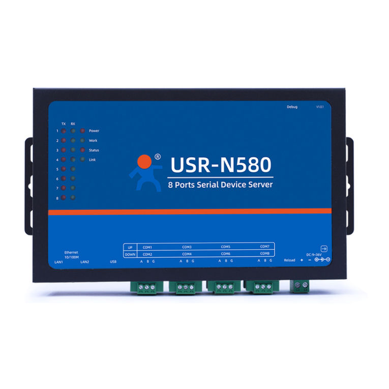
USR-N580
8 RS485 to Ethernet device server
1.2. Features
The USR-N5X0 field-mount serial device server series share the same software platform on different available hardware components.
It provides
High-performance CPU processing ability,using 32-bit Arm Cortex-M7 core CPU, up to 400MHz frequency
Provides remote serial access over the Internet for industrial serial devices
10/100Mbps Ethernet port and support Auto MDI/MDIX
Software selectable RS-232/422/485 3-in-1 serial port(N5X0 models)
Rugged metal housing with IP30 protection for wall or optional DIN-Rail mount
Built-in 15KV ESD serial port protection
Supports a wide industrial operating temperature,-40℃~85℃
Baud rate: 0.6~921.6 Kbps(maximum 230.4Kbps for N520-6 model), and any baud rate setting, support None, Odd, Even, Mark,
Space Parity bit(firmware V2.0.0 or later)
Supports Hardware and Software flow control
Flexible serial port data framing setting, which can satisfy user’s various demands for data packets segmentation
Versatile operation modes: TCP Server, TCP Client, UDP, HTTP client, Websocket server
Support virtual COM ,COM Port Redirector USR-VCOM(windows)
Modbus Ethernet-to-Serial support (Modbus/TCP, Modbus/RTU) for seamless integration of serial Modbus devices
Provides rich configuration access, including: Windows configuration tool, and Web Browser

User Manual
Your TrustWorthy Industrial IoT Partner www.pusr.com
6
Firmware upgrading via Web Browser and Windows configuration tool
Easy-to-use Windows configuration tool for auto discovery, multiple device setting and monitoring
Choice of power input: AC-DC adapter(DC Jack) or DC direct(Terminal Block)
High security via certificate verification SSL/TLS encryption for serial data transmission,HTTPS,TCPS,MQTTS(firmware V2.0.0 or
later)
Support modbus RTU master,edge computing, modbus gateway,MQTT gateway(firmware V2.0.0 or later)
Support SNMP V1/V2c(firmware V2.0.0 or later)

User Manual
Your TrustWorthy Industrial IoT Partner www.pusr.com
7
2. Get started
Since the USR-N5X0 Series is connected through a TCP/IP network, you may need to know some basic facts about networking in
order to connect the server correctly.
Specifications and dimensions are not provided in this manual since they may differ considerably based on the hardware purchase.
Please refer to datasheet of each model for more information.
2.1. Installation
You can choose whether to plug in the other peripheral ports at this point or do it later depending on the actual location of the device
or level of comfort for performing such operation.
2.1.1. Wall mounting
The wall mounting option provides better shock and vibration resistance than the DIN-Rail vertical mount.
Locate the installation site and place the device against the wall. Use the wall mount plates as a guide to mark the locations of
the screw holes.
Drill two holes over the two marked locations on the wall. Insert the wall sinks into the walls.
Insert the screws into the wall sinks. Leave a 2 mm gap between the wall and the screw head to allow for wall mount plate
insertion.
Align the wall mount plate over the screws on the wall. Hang the device on two screws and slide it downward to lock in place,
then tighten the screw to enhance stability, see the following Fig.1.
Fig. 1 Wall mount installation
For device disassembling please power off the device and unscrew the screw on the wall about 2mm. Lift the device upward
slightly, take out the device,
2.1.2. DIN-Rail mounting
DIN-Rail mount kits must be purchased separately. They are not provided with the N5X0.
If you have purchased the DIN-Rail mount kit, proceed to place the screws on the back of the device as show in Fig.2.

User Manual
Your TrustWorthy Industrial IoT Partner www.pusr.com
8
Fig. 2 Fix DIN-Rail mount kit
Position the rear panel of the device directly in front of the DIN-Rail, making sure that the top of the DIN-Rail clip hooks over the
top of the DIN-Rail , as shown in Fig.3.
Fig. 3 Install DIN-Rail mounting kit
Once the DIN-Rail is seated correctly in the DIN-Rail clip, press the front of the device to rotate the device down and into the
release tab on the DIN-Rail clip. If seated correctly, the bottom of the DIN-Rail should be fully inserted in the release tab.

User Manual
Your TrustWorthy Industrial IoT Partner www.pusr.com
9
Fig. 4 Correctly installed DIN-Rail kit
Proceed to Fig.5 if you want to remove the device from DIN-Rail. Push down on the top of the DIN rail clip release tab with your
finger. As the clip releases, lift the bottom of the device, as shown in the following illustration.
Fig. 5 Remove the DIN-Rail
2.2. Serial port
The USR-N5X0 supports the RS-232, RS-422, and RS-485 protocols,adopts DB9 male connector and is software configurable. The
serial port pin assignments are given in the table 2.

User Manual
Your TrustWorthy Industrial IoT Partner www.pusr.com
10
Fig. 6 DB9 male connector pin
Table 2 DB9 Male Pin Assignment(N5X0 models)
Pin
RS232
RS422
RS485
1
--
--
--
2
RXD
Rx+
3
TXD
Tx-
B-
4
5
GND
6
7
RTS
Tx-
A+
8
CTS
Rx-
9
The USR-N5X0-6 supports the RS-232 and RS-485 protocols, and is software configurable. And RS232 adopts DB9 male
connector,RS485 adopts terminal block. The DB9 pin assignment is same to table 2(RS232).
Fig. 7 N520-6 serial port
The USR-N5X0-4 supports only RS-485 protocols, and adopts 3-pin 5.08mm pitch industrial terminal blocks. The serial port pin
assignments are shown in Fig.8.

User Manual
Your TrustWorthy Industrial IoT Partner www.pusr.com
11
Fig. 8 N510-4 terminal block
2.3. Power supply
The USR-N5X0 serial device server provides 2-pin power supply input terminal blocks and DC jack. The power supply support
anti-reverse protection. Power supply range: 5~36VDC.
Fig. 9 N520 back view
Although internal grounding has been done inside, in order to help limit the effects of noise caused by electromagnetic interference
(EMI) and protect your device, it is still strongly advised to ground the device properly. There is a grounding screw next to the terminal
block,you should connect it to the grounding at all times.
2.4. Ethernet RJ45 interface
The 10Base-T/100Base-TX adaptive Ethernet RJ45 interface supports automatic MDI/MDIX connection, refer to Fig.10 below for the
pin distribution of the RJ45 interface. USR-N5X0 serial servers adopt RJ45 interface with light, as shown in the picture below.
Fig. 10 RJ45 with light
Table 3 Ethernet pin assignments

User Manual
Your TrustWorthy Industrial IoT Partner www.pusr.com
12
Pin number
Signal name
1
Send data+(TD+)
2
Send data-(TD-)
3
Receive data+(RD+)
6
Receive data-(RD-)
4,5,7,8
Unused
2.5. LED indicators
The USR-N5X0 serial device server provides LED indicators to monitor the device working status with a comprehensive simplified
troubleshooting, the function of each LED is described in the table as below.
Table 4 LED indicators
LED name
status
description
PWR
Steady on
Power supply is normal
Off
No power supply or abnormal power supply
WORK
Blinking
Power is on and the device is ready. System is booted up
and running
TXN
Blinking
Serial port is transmitting data
RXN
Blinking
Serial port is receiving data
2.6. Factory default settings
The USR-N5X0 serial device server comes with the following default settings.
Table 5 Default parameters
Parameter
Default Values
User Name
admin
Password
admin
Device IP
192.168.0.7
Subnet Mask
255.255.255.0
Gateway IP
192.168.0.1
COM port
115200,None,8,1
COM operation mode
TCP server,23
MQTT
Disable (firmware V2 version)
Edge computing
Disable (firmware V2 version)
2.7. Quick test
USR-N5X0 series serial server has a built-in Web server, which provides a convenient way to access and configure the serial server.
Users can use Edge , Firefox or Google browser to access it. This chapter is a quick introduction to the USR-N5X0 series of serial
server products. It is recommended that users read this chapter and follow the instructions once for the system, and you will have a
basic understanding of the product. For specific function details and instructions, please refer to the subsequent chapters.

User Manual
Your TrustWorthy Industrial IoT Partner www.pusr.com
13
2.7.1. Download the software
Download the setting software from PUSR’s website:
https://www.pusr.com/support/downloads/H7-version-set-up-software.html
https://www.pusr.com/support/downloads/usr-tcp232-test-V13.html
You may find it in the download section under your product page. Run the software when the installation has been completed as
shown in Fig.11 and Fig.12.
It is strongly recommended for the users to set the Network Parameters through configuration tool first. Other device-specific
configurations can later be carried out via user-friendly Web-Interface.
Fig. 11 Windows configuration tool
Fig. 12 Test assistant
2.7.2. Hardware connection
For fast networking of USR-N5X0 series serial server, you need to prepare a PC, a router, a serial server, a network cable, a serial
cable, and a DC12V/1A power supply. The hardware connection is shown in Fig. 13. To establish a TCP / IP network all devices must be

User Manual
Your TrustWorthy Industrial IoT Partner www.pusr.com
14
connected to the same network either locally or via gateway connections.
Fig. 13 Hardware connection
Connect the power line with the N5X0 power input. If the power is properly supplied, the “PWR” LED will show a solid red color.
After the system is ready, the “WORK” LED will blink.
Connect one end of the Ethernet cable to the N5X0’s 10/100M Ethernet port and the other end of the cable to the same Ethernet
network(same router or switch).
Connect a serial data cable(USB to RS232 or RS485) between the N5X0 and PC.
2.7.3. Network configuration(Step1)
The Broadcast Search function is used to locate all N5X0 device servers that are connected to the same LAN as your computer. Since
the Broadcast Search function searches by MAC address and not IP address, all N5X0 connected to the LAN will be located,
regardless of whether or not they are part of the same subnet as the host.
In EthernetTool, click Search to search your LAN for N5X0 device servers. When your unit appears in the search results, you can click
device to select it and change the IP type to DHCH, save your change. Wait for 5s and search it again.
Fig. 14 IP network setting
When accessing the serial server through the Web, the IP address of the serial server and the PC must be in the same network
segment. After changing the IP address of the N5X0, you can access the Web page of the N5X0 series serial server through browser
and perform related configuration operations on it. The user name and initial password are both "admin".After entering the user name
and password, click "OK" and the server will authenticate. After success, you will enter the main page of the Web server, as shown in
Fig.15. The following uses firmware V2 version as an example. For details about the V1 version web page, see Section 3.1.

User Manual
Your TrustWorthy Industrial IoT Partner www.pusr.com
15
Fig. 15 The main interface of the Web server
The IP address of the PC must be modified to ensure that it is in the same local area network as the IP of the serial server if you want
to connect N5X0 to PC directly via a net cable. The default IP address of serial server is: 192.168.0.7. Set the PC's IP address as:
192.168.0.X (X is any valid value from 2 to 253 except 7). The specific Windows system operation page is shown in Fig.16. you can
access the Web page of the USR-N5X0 series serial server through browser as mentioned above.
Fig. 16 IP setting of PC
2.7.4. Data transmission test(Step2 and 3)
You can select an operation mode in socket setting page, but for now we use default parameters to test, i.e TCP server. Now

User Manual
Your TrustWorthy Industrial IoT Partner www.pusr.com
16
USR-TCP232-Test works as TCP client, you need configure the server IP and port, that is 172.16.14.158:23 of USR-N5X0 serial device
server, the IP address of PC is 172.16.14.15.
In the serial port setting module, you can configure communication parameters for the serial ports RS485 and RS232, as shown in the
figure below. When configuring a serial network you need to set the following within each device-Baud rate,Parity,Stop bits,Data bits
and keep serial port parameters consistent in the same network. We now configure the COM Settings to operate as required for the
N5X0 devices. Go to the Port1 Settings tab for confirming values of parameters.
Fig.17 shows an example of parameters setting to test transparent transmission.
Fig. 17 Transparent transmission test
2.8. Reload factory settings button
Press the “ Reload” button (inside a small hole) on the back panel for 3-15 seconds and then release or follow the procedure in
Section 3.1.6, to restore the USR-N5X0 Series Industrial Serial Device Server to the factory default settings.
2.9. Technical support and assistance
Please visit the USR IoT website: https://www.pusr.com where you can find the latest information about the product.
Contact your distributor, sales representative, or PUSR's support center:
http://h.usriot.com/index.php?c=frontTicket&m=sign for technical support if you need additional assistance. Please have the following
information ready before you submit a ticket:
– Product model
– Description of your peripheral attachments

User Manual
Your TrustWorthy Industrial IoT Partner www.pusr.com
17
– Description of your software (firmware version, application,function description,etc.)
– A complete description of the issue and steps to reproduce

User Manual
Your TrustWorthy Industrial IoT Partner www.pusr.com
18
3. Configuration and parameter details
3.1. Web interface(V1 version)
Every USR-N5X0 Industrial Serial Device Server is equipped with a built-in web server in the firmware. Therefore, the device can be
accessed by using a web browser for configuring by entering the device’s IP address in the URL field of your web browser. An
authentication will be required and you will have to enter the username (Default value is “admin”) and password (Default value is
“admin”) for accessing the web interface as shown in Fig. 18. This approach (web interface) for configuring your device is the most
user-friendly. It is the most recommended and the most common method used for USR-N5X0 Serial Device Server Series. Please go
to its corresponding section for a detailed explanation.
Fig. 18 Authentication Required for Accessing Web Interface
3.1.1. Status
After entering the correct user name and password and the authentication is successful, you will enter the main page of the Web, as
shown in Fig.19. The main page can be roughly divided into three areas. The upper area displays the logo, the lower left area is the
function menu area, the middle area is the main function display area, and the lower right area is the help document area. Fig.19
illustrates the status page of the web interface.

User Manual
Your TrustWorthy Industrial IoT Partner www.pusr.com
19
Fig. 19 The main interface of the Web server
The function of the device status part is to display some specific information of the current device, including module name,firmware
version, IP address, DNS, MAC address, running time and serial port status.
Table 6 Status list
Parameter Item
Description
Module name
The name of the serial server, which can be customized by the user on the "Miscellaneous settings" page.
Firmware version
The current software version of the serial server.
IP address
The IP address of the serial server.
MAC address
The MAC address of the serial server.
Running time
Total time after the device start work. It will starts from 0 after reboot.
Port status
The working status of checked serial port. Select the serial port currently to be displayed
1Conn Status A(ETH): connection status of socket A.
IDLE:Initialization status
LISTEN:When the module works as TCP Server, it is listening for connection access
CONNECTING:Works as TCP client, the module is establishing a connection to the TCP Server
CONNECTED:Works as TCP server, the TCP connection to TCP server of the module has been
established
CONNECTED(n):Number of TCP clients connected to the module
ERROR:The module is abnormally disconnected
2Tx Count A(ETH): To count how many bytes be send to internet.
3Rx Count A(ETH): To count how many bytes received from internet.
This manual suits for next models
4
Table of contents
Other USR IOT Server manuals
Popular Server manuals by other brands
HP
HP ProLiant XL450 Gen10 Maintenance and service guide
Bluegiga Technologies
Bluegiga Technologies WRAP User’s and Developer’s Guide
Moxa Technologies
Moxa Technologies NPort IA5000A Series user manual
Oase
Oase WECS II 2048/DMX/02 operating instructions
Perle
Perle IOLAN CSS Cli reference guide

HP
HP ProLiant BL360 G5 Maintenance and service guide
